maintenance YAMAHA YZ450F 2005 Notices Demploi (in French)
[x] Cancel search | Manufacturer: YAMAHA, Model Year: 2005, Model line: YZ450F, Model: YAMAHA YZ450F 2005Pages: 646, PDF Size: 16.06 MB
Page 81 of 646
SPEC
2 - 10 Item Standard
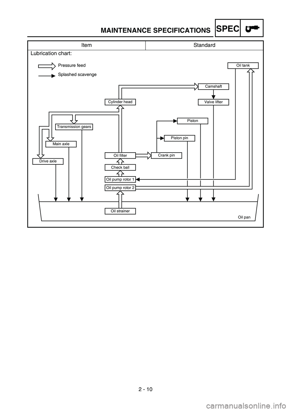
Lubrication chart:
Pressure feed
Splashed scavenge
Oil strainer
Oil pan Oil pump rotor 2
Oil pump rotor 1
Oil tank
Oil filter
Check ball
Cylinder head
Crank pinPiston pinPiston
Drive axleMain axleTransmission gears
Camshaft
Valve lifter
MAINTENANCE SPECIFICATIONS
Page 82 of 646
SPEC
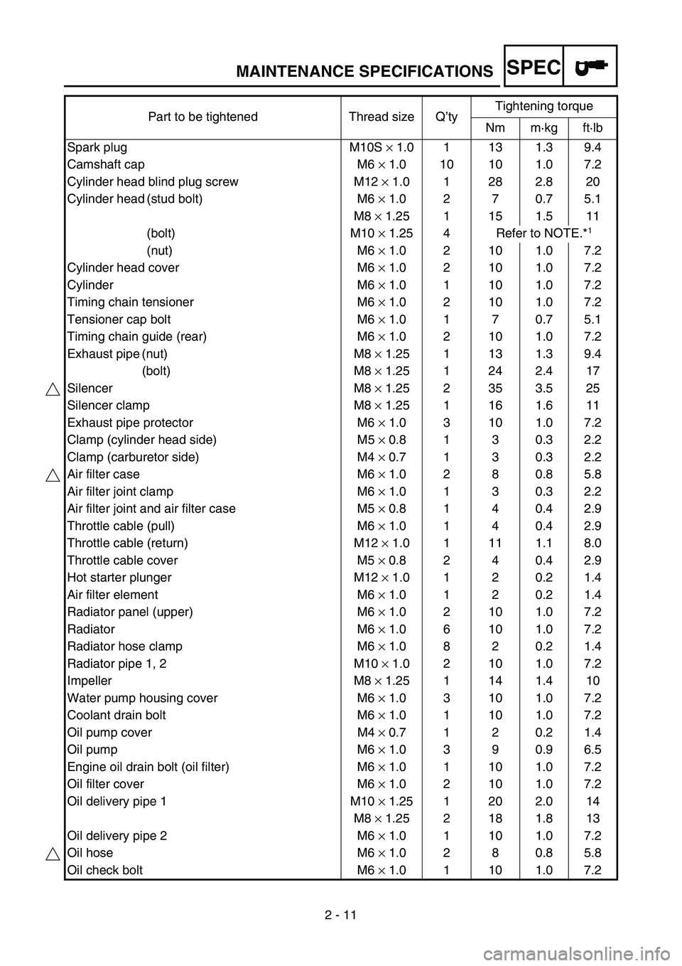
2 - 11 Part to be tightened Thread size Q’tyTightening torque
Nm m·kg ft·lb
Spark plug M10S × 1.0 1 13 1.3 9.4
Camshaft cap M6 × 1.0 10 10 1.0 7.2
Cylinder head blind plug screw M12 × 1.0 1 28 2.8 20
Cylinder head (stud bolt) M6 × 1.0 2 7 0.7 5.1
M8 × 1.25 1 15 1.5 11
(bolt) M10 × 1.25 4 Refer to NOTE.*
1
(nut) M6 × 1.0 2 10 1.0 7.2
Cylinder head cover M6 × 1.0 2 10 1.0 7.2
Cylinder M6 × 1.0 1 10 1.0 7.2
Timing chain tensioner M6 × 1.0 2 10 1.0 7.2
Tensioner cap bolt M6 × 1.0 1 7 0.7 5.1
Timing chain guide (rear) M6 × 1.0 2 10 1.0 7.2
Exhaust pipe (nut) M8 × 1.25 1 13 1.3 9.4
(bolt) M8 × 1.25 1 24 2.4 17
Silencer M8 × 1.25 2 35 3.5 25
Silencer clamp M8 × 1.25 1 16 1.6 11
Exhaust pipe protector M6 × 1.0 3 10 1.0 7.2
Clamp (cylinder head side) M5 × 0.8 1 3 0.3 2.2
Clamp (carburetor side) M4 × 0.7 1 3 0.3 2.2
Air filter case M6 × 1.0 2 8 0.8 5.8
Air filter joint clamp M6 × 1.0 1 3 0.3 2.2
Air filter joint and air filter case M5 × 0.8 1 4 0.4 2.9
Throttle cable (pull) M6 × 1.0 1 4 0.4 2.9
Throttle cable (return) M12 × 1.0 1 11 1.1 8.0
Throttle cable cover M5 × 0.8 2 4 0.4 2.9
Hot starter plunger M12 × 1.0 1 2 0.2 1.4
Air filter element M6 × 1.0 1 2 0.2 1.4
Radiator panel (upper) M6 × 1.0 2 10 1.0 7.2
Radiator M6 × 1.0 6 10 1.0 7.2
Radiator hose clamp M6 × 1.0 8 2 0.2 1.4
Radiator pipe 1, 2 M10 × 1.0 2 10 1.0 7.2
Impeller M8 × 1.25 1 14 1.4 10
Water pump housing cover M6 × 1.0 3 10 1.0 7.2
Coolant drain bolt M6 × 1.0 1 10 1.0 7.2
Oil pump cover M4 × 0.7 1 2 0.2 1.4
Oil pump M6 × 1.0 3 9 0.9 6.5
Engine oil drain bolt (oil filter) M6 × 1.0 1 10 1.0 7.2
Oil filter cover M6 × 1.0 2 10 1.0 7.2
Oil delivery pipe 1 M10 × 1.25 1 20 2.0 14
M8 × 1.25 2 18 1.8 13
Oil delivery pipe 2 M6 × 1.0 1 10 1.0 7.2
Oil hose M6 × 1.0 2 8 0.8 5.8
Oil check bolt M6 × 1.0 1 10 1.0 7.2
MAINTENANCE SPECIFICATIONS
Page 83 of 646
SPEC
2 - 12
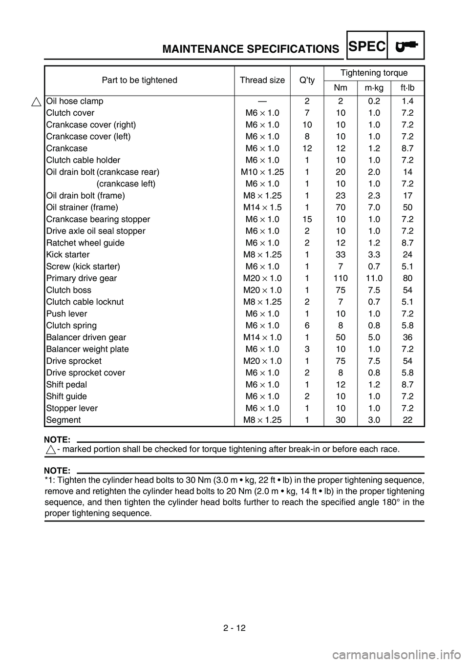
NOTE:
- marked portion shall be checked for torque tightening after break-in or before each race.
NOTE:
*1: Tighten the cylinder head bolts to 30 Nm (3.0 m kg, 22 ft lb) in the proper tightening sequence,
remove and retighten the cylinder head bolts to 20 Nm (2.0 m kg, 14 ft lb) in the proper tightening
sequence, and then tighten the cylinder head bolts further to reach the specified angle 180° in the
proper tightening sequence.Oil hose clamp—220.21.4
Clutch cover M6 × 1.0 7 10 1.0 7.2
Crankcase cover (right) M6 × 1.0 10 10 1.0 7.2
Crankcase cover (left) M6 × 1.0 8 10 1.0 7.2
Crankcase M6 × 1.0 12 12 1.2 8.7
Clutch cable holder M6 × 1.0 1 10 1.0 7.2
Oil drain bolt (crankcase rear) M10 × 1.25 1 20 2.0 14
(crankcase left) M6 × 1.0 1 10 1.0 7.2
Oil drain bolt (frame) M8 × 1.25 1 23 2.3 17
Oil strainer (frame) M14 × 1.5 1 70 7.0 50
Crankcase bearing stopper M6 × 1.0 15 10 1.0 7.2
Drive axle oil seal stopper M6 × 1.0 2 10 1.0 7.2
Ratchet wheel guide M6 × 1.0 2 12 1.2 8.7
Kick starter M8 × 1.25 1 33 3.3 24
Screw (kick starter) M6 × 1.0 1 7 0.7 5.1
Primary drive gear M20 × 1.0 1 110 11.0 80
Clutch boss M20 × 1.0 1 75 7.5 54
Clutch cable locknut M8 × 1.25 2 7 0.7 5.1
Push lever M6 × 1.0 1 10 1.0 7.2
Clutch spring M6 × 1.0 6 8 0.8 5.8
Balancer driven gear M14 × 1.0 1 50 5.0 36
Balancer weight plate M6 × 1.0 3 10 1.0 7.2
Drive sprocket M20 × 1.0 1 75 7.5 54
Drive sprocket cover M6 × 1.0 2 8 0.8 5.8
Shift pedal M6 × 1.0 1 12 1.2 8.7
Shift guide M6 × 1.0 2 10 1.0 7.2
Stopper lever M6 × 1.0 1 10 1.0 7.2
Segment M8 × 1.25 1 30 3.0 22 Part to be tightened Thread size Q’tyTightening torque
Nm m·kg ft·lb
MAINTENANCE SPECIFICATIONS
Page 84 of 646
SPEC
2 - 13
EC212201
CHASSIS
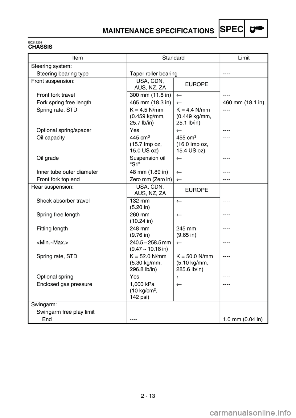
Item Standard Limit
Steering system:
Steering bearing type Taper roller bearing ----
Front suspension: USA, CDN,
AUS, NZ, ZAEUROPE
Front fork travel 300 mm (11.8 in)← ----
Fork spring free length 465 mm (18.3 in)← 460 mm (18.1 in)
Spring rate, STD K = 4.5 N/mm
(0.459 kg/mm,
25.7 lb/in)K = 4.4 N/mm
(0.449 kg/mm,
25.1 lb/in)----
Optional spring/spacer Yes← ----
Oil capacity 445 cm
3
(15.7 Imp oz,
15.0 US oz) 455 cm3
(16.0 Imp oz,
15.4 US oz) ----
Oil grade Suspension oil
“S1”← ----
Inner tube outer diameter 48 mm (1.89 in)← ----
Front fork top end Zero mm (Zero in)← ----
Rear suspension: USA, CDN,
AUS, NZ, ZAEUROPE
Shock absorber travel 132 mm
(5.20 in)← ----
Spring free length 260 mm
(10.24 in)← ----
Fitting length 248 mm
(9.76 in)245 mm
(9.65 in)----
(9.47 ~ 10.18 in)← ----
Spring rate, STD K = 52.0 N/mm
(5.30 kg/mm,
296.8 lb/in)K = 50.0 N/mm
(5.10 kg/mm,
285.6 lb/in)----
Optional spring Yes← ----
Enclosed gas pressure 1,000 kPa
(10 kg/cm
2,
142 psi)← ----
Swingarm:
Swingarm free play limit
End ---- 1.0 mm (0.04 in)
MAINTENANCE SPECIFICATIONS
Page 85 of 646
SPEC
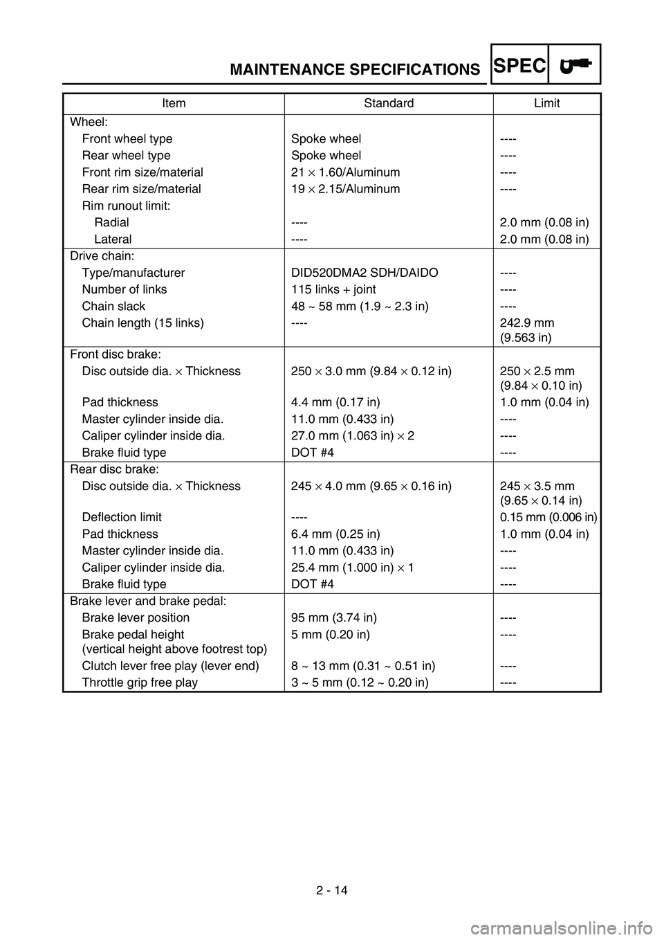
2 - 14 Wheel:
Front wheel type Spoke wheel ----
Rear wheel type Spoke wheel ----
Front rim size/material 21 × 1.60/Aluminum ----
Rear rim size/material 19 × 2.15/Aluminum ----
Rim runout limit:
Radial ---- 2.0 mm (0.08 in)
Lateral ---- 2.0 mm (0.08 in)
Drive chain:
Type/manufacturer DID520DMA2 SDH/DAIDO ----
Number of links 115 links + joint ----
Chain slack 48 ~ 58 mm (1.9 ~ 2.3 in) ----
Chain length (15 links) ---- 242.9 mm
(9.563 in)
Front disc brake:
Disc outside dia. × Thickness 250 × 3.0 mm (9.84 × 0.12 in) 250 × 2.5 mm
(9.84 × 0.10 in)
Pad thickness 4.4 mm (0.17 in) 1.0 mm (0.04 in)
Master cylinder inside dia. 11.0 mm (0.433 in) ----
Caliper cylinder inside dia. 27.0 mm (1.063 in) × 2 ----
Brake fluid type DOT #4 ----
Rear disc brake:
Disc outside dia. × Thickness 245 × 4.0 mm (9.65 × 0.16 in) 245 × 3.5 mm
(9.65 × 0.14 in)
Deflection limit ---- 0.15 mm (0.006 in)
Pad thickness 6.4 mm (0.25 in) 1.0 mm (0.04 in)
Master cylinder inside dia. 11.0 mm (0.433 in) ----
Caliper cylinder inside dia. 25.4 mm (1.000 in) × 1 ----
Brake fluid type DOT #4 ----
Brake lever and brake pedal:
Brake lever position 95 mm (3.74 in) ----
Brake pedal height
(vertical height above footrest top)5 mm (0.20 in) ----
Clutch lever free play (lever end) 8 ~ 13 mm (0.31 ~ 0.51 in) ----
Throttle grip free play 3 ~ 5 mm (0.12 ~ 0.20 in) ----Item Standard Limit
MAINTENANCE SPECIFICATIONS
Page 86 of 646
SPEC
2 - 15
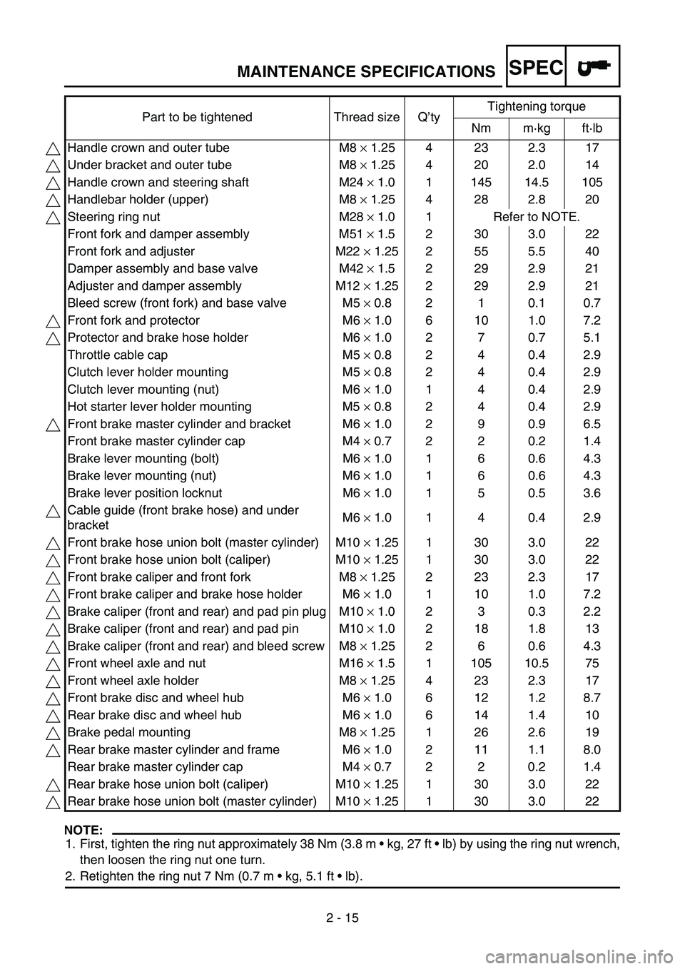
NOTE:
1. First, tighten the ring nut approximately 38 Nm (3.8 m kg, 27 ft lb) by using the ring nut wrench,
then loosen the ring nut one turn.
2. Retighten the ring nut 7 Nm (0.7 m kg, 5.1 ft lb). Part to be tightened Thread size Q’tyTightening torque
Nm m·kg ft·lb
Handle crown and outer tube M8 × 1.25 4 23 2.3 17
Under bracket and outer tube M8 × 1.25 4 20 2.0 14
Handle crown and steering shaft M24 × 1.0 1 145 14.5 105
Handlebar holder (upper) M8 × 1.25 4 28 2.8 20
Steering ring nut M28 × 1.0 1 Refer to NOTE.
Front fork and damper assembly M51 × 1.5 2 30 3.0 22
Front fork and adjuster M22 × 1.25 2 55 5.5 40
Damper assembly and base valve M42 × 1.5 2 29 2.9 21
Adjuster and damper assembly M12 × 1.25 2 29 2.9 21
Bleed screw (front fork) and base valve M5 × 0.8 2 1 0.1 0.7
Front fork and protector M6 × 1.0 6 10 1.0 7.2
Protector and brake hose holder M6 × 1.0 2 7 0.7 5.1
Throttle cable cap M5 × 0.8 2 4 0.4 2.9
Clutch lever holder mounting M5 × 0.8 2 4 0.4 2.9
Clutch lever mounting (nut) M6 × 1.0 1 4 0.4 2.9
Hot starter lever holder mounting M5 × 0.8 2 4 0.4 2.9
Front brake master cylinder and bracket M6 × 1.0 2 9 0.9 6.5
Front brake master cylinder cap M4 × 0.7 2 2 0.2 1.4
Brake lever mounting (bolt) M6 × 1.0 1 6 0.6 4.3
Brake lever mounting (nut) M6 × 1.0 1 6 0.6 4.3
Brake lever position locknut M6 × 1.0 1 5 0.5 3.6
Cable guide (front brake hose) and under
bracketM6 × 1.0 1 4 0.4 2.9
Front brake hose union bolt (master cylinder) M10 × 1.25 1 30 3.0 22
Front brake hose union bolt (caliper) M10 × 1.25 1 30 3.0 22
Front brake caliper and front fork M8 × 1.25 2 23 2.3 17
Front brake caliper and brake hose holder M6 × 1.0 1 10 1.0 7.2
Brake caliper (front and rear) and pad pin plug M10 × 1.0 2 3 0.3 2.2
Brake caliper (front and rear) and pad pin M10 × 1.0 2 18 1.8 13
Brake caliper (front and rear) and bleed screw M8 × 1.25 2 6 0.6 4.3
Front wheel axle and nut M16 × 1.5 1 105 10.5 75
Front wheel axle holder M8 × 1.25 4 23 2.3 17
Front brake disc and wheel hub M6 × 1.0 6 12 1.2 8.7
Rear brake disc and wheel hub M6 × 1.0 6 14 1.4 10
Brake pedal mounting M8 × 1.25 1 26 2.6 19
Rear brake master cylinder and frame M6 × 1.0 2 11 1.1 8.0
Rear brake master cylinder cap M4 × 0.7 2 2 0.2 1.4
Rear brake hose union bolt (caliper) M10 × 1.25 1 30 3.0 22
Rear brake hose union bolt (master cylinder) M10 × 1.25 1 30 3.0 22
MAINTENANCE SPECIFICATIONS
Page 87 of 646
SPEC
2 - 16
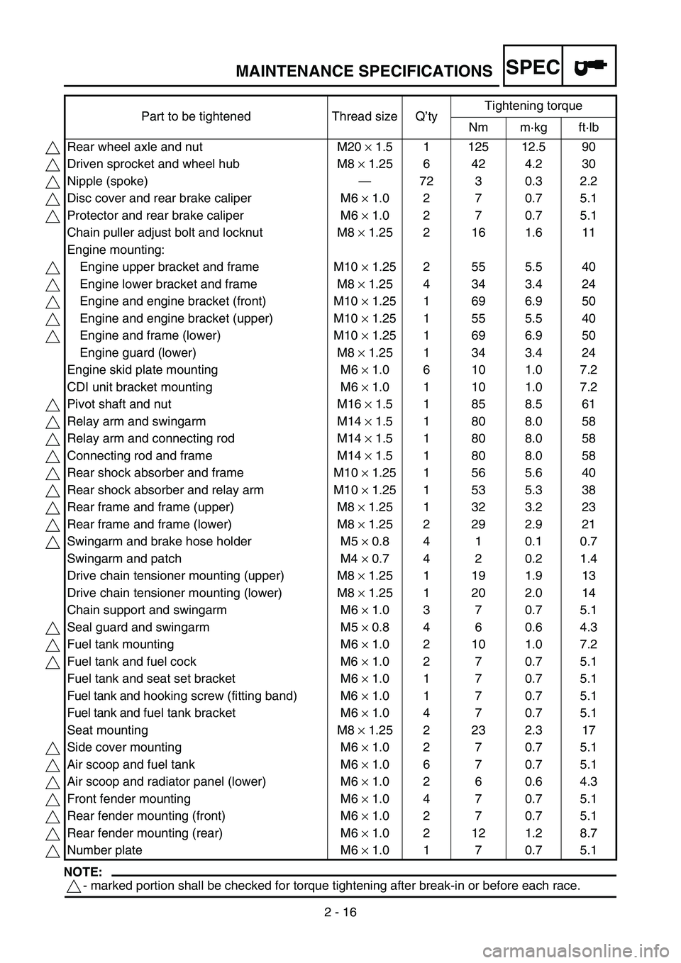
NOTE:
- marked portion shall be checked for torque tightening after break-in or before each race.Part to be tightened Thread size Q’tyTightening torque
Nm m·kg ft·lb
Rear wheel axle and nut M20 × 1.5 1 125 12.5 90
Driven sprocket and wheel hub M8 × 1.25 6 42 4.2 30
Nipple (spoke)—72 3 0.3 2.2
Disc cover and rear brake caliper M6 × 1.0 2 7 0.7 5.1
Protector and rear brake caliper M6 × 1.0 2 7 0.7 5.1
Chain puller adjust bolt and locknut M8 × 1.25 2 16 1.6 11
Engine mounting:
Engine upper bracket and frame M10 × 1.25 2 55 5.5 40
Engine lower bracket and frame M8 × 1.25 4 34 3.4 24
Engine and engine bracket (front) M10 × 1.25 1 69 6.9 50
Engine and engine bracket (upper) M10 × 1.25 1 55 5.5 40
Engine and frame (lower) M10 × 1.25 1 69 6.9 50
Engine guard (lower) M8 × 1.25 1 34 3.4 24
Engine skid plate mounting M6 × 1.0 6 10 1.0 7.2
CDI unit bracket mounting M6 × 1.0 1 10 1.0 7.2
Pivot shaft and nut M16 × 1.5 1 85 8.5 61
Relay arm and swingarm M14 × 1.5 1 80 8.0 58
Relay arm and connecting rod M14 × 1.5 1 80 8.0 58
Connecting rod and frame M14 × 1.5 1 80 8.0 58
Rear shock absorber and frame M10 × 1.25 1 56 5.6 40
Rear shock absorber and relay arm M10 × 1.25 1 53 5.3 38
Rear frame and frame (upper) M8 × 1.25 1 32 3.2 23
Rear frame and frame (lower) M8 × 1.25 2 29 2.9 21
Swingarm and brake hose holder M5 × 0.8 4 1 0.1 0.7
Swingarm and patch M4 × 0.7 4 2 0.2 1.4
Drive chain tensioner mounting (upper) M8 × 1.25 1 19 1.9 13
Drive chain tensioner mounting (lower) M8 × 1.25 1 20 2.0 14
Chain support and swingarm M6 × 1.0 3 7 0.7 5.1
Seal guard and swingarm M5 × 0.8 4 6 0.6 4.3
Fuel tank mounting M6 × 1.0 2 10 1.0 7.2
Fuel tank and fuel cock M6 × 1.0 2 7 0.7 5.1
Fuel tank and seat set bracket M6 × 1.0 1 7 0.7 5.1
Fuel tank and hooking screw (fitting band) M6 × 1.0 1 7 0.7 5.1
Fuel tank and fuel tank bracket M6 × 1.0 4 7 0.7 5.1
Seat mounting M8 × 1.25 2 23 2.3 17
Side cover mounting M6 × 1.0 2 7 0.7 5.1
Air scoop and fuel tank M6 × 1.0 6 7 0.7 5.1
Air scoop and radiator panel (lower) M6 × 1.0 2 6 0.6 4.3
Front fender mounting M6 × 1.0 4 7 0.7 5.1
Rear fender mounting (front) M6 × 1.0 2 7 0.7 5.1
Rear fender mounting (rear) M6 × 1.0 2 12 1.2 8.7
Number plate M6 × 1.0 1 7 0.7 5.1
MAINTENANCE SPECIFICATIONS
Page 88 of 646
SPEC
2 - 17
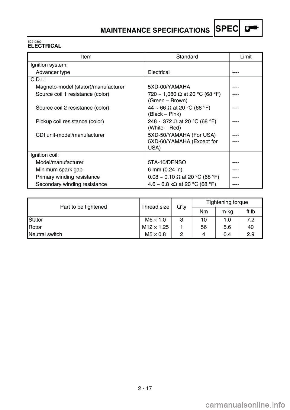
EC212300
ELECTRICAL
Item Standard Limit
Ignition system:
Advancer type Electrical ----
C.D.I.:
Magneto-model (stator)/manufacturer 5XD-00/YAMAHA ----
Source coil 1 resistance (color) 720 ~ 1,080 Ω at 20 °C (68 °F)
(Green – Brown)----
Source coil 2 resistance (color) 44 ~ 66 Ω at 20 °C (68 °F)
(Black – Pink)----
Pickup coil resistance (color) 248 ~ 372 Ω at 20 °C (68 °F)
(White – Red)----
CDI unit-model/manufacturer 5XD-50/YAMAHA (For USA)
5XD-60/YAMAHA (Except for
USA)----
----
Ignition coil:
Model/manufacturer 5TA-10/DENSO ----
Minimum spark gap 6 mm (0.24 in) ----
Primary winding resistance 0.08 ~ 0.10 Ω at 20 °C (68 °F) ----
Secondary winding resistance 4.6 ~ 6.8 kΩ at 20 °C (68 °F) ----
Part to be tightened Thread size Q’tyTightening torque
Nm m·kg ft·lb
Stator M6 × 1.0 3 10 1.0 7.2
Rotor M12 × 1.25 1 56 5.6 40
Neutral switch M5 × 0.8 2 4 0.4 2.9
MAINTENANCE SPECIFICATIONS
Page 142 of 646
3 - 1
INSP
ADJ
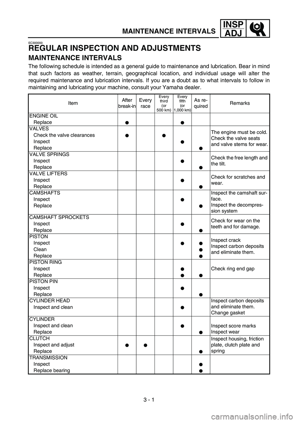
MAINTENANCE INTERVALS
EC300000
REGULAR INSPECTION AND ADJUSTMENTS
MAINTENANCE INTERVALS
The following schedule is intended as a general guide to maintenance and lubrication. Bear in mind
that such factors as weather, terrain, geographical location, and individual usage will alter the
required maintenance and lubrication intervals. If you are a doubt as to what intervals to follow in
maintaining and lubricating your machine, consult your Yamaha dealer.
ItemAfter
break-inEvery
race
Every
third
(or
500 km)Every
fifth
(or
1,000 km)As re-
quiredRemarks
ENGINE OIL
Replace
VALVES
The engine must be cold.
Check the valve seats
and valve stems for wear. Check the valve clearances
Inspect
Replace
VALVE SPRINGS
Check the free length and
the tilt. Inspect
Replace
VALVE LIFTERS
Check for scratches and
wear. Inspect
Replace
CAMSHAFTS Inspect the camshaft sur-
face.
Inspect the decompres-
sion system Inspect
Replace
CAMSHAFT SPROCKETS
Check for wear on the
teeth and for damage. Inspect
Replace
PISTON
Inspect crack
Inspect carbon deposits
and eliminate them. Inspect
Clean
Replace
PISTON RING
Check ring end gap Inspect
Replace
PISTON PIN
Inspect
Replace
CYLINDER HEAD Inspect carbon deposits
and eliminate them.
Change gasket Inspect and clean
CYLINDER
Inspect and clean
Inspect score marks
Inspect wear
Replace
CLUTCH
Inspect housing, friction
plate, clutch plate and
spring Inspect and adjust
Replace
TRANSMISSION
Inspect
Replace bearing
Page 143 of 646
3 - 2
INSP
ADJ
MAINTENANCE INTERVALS
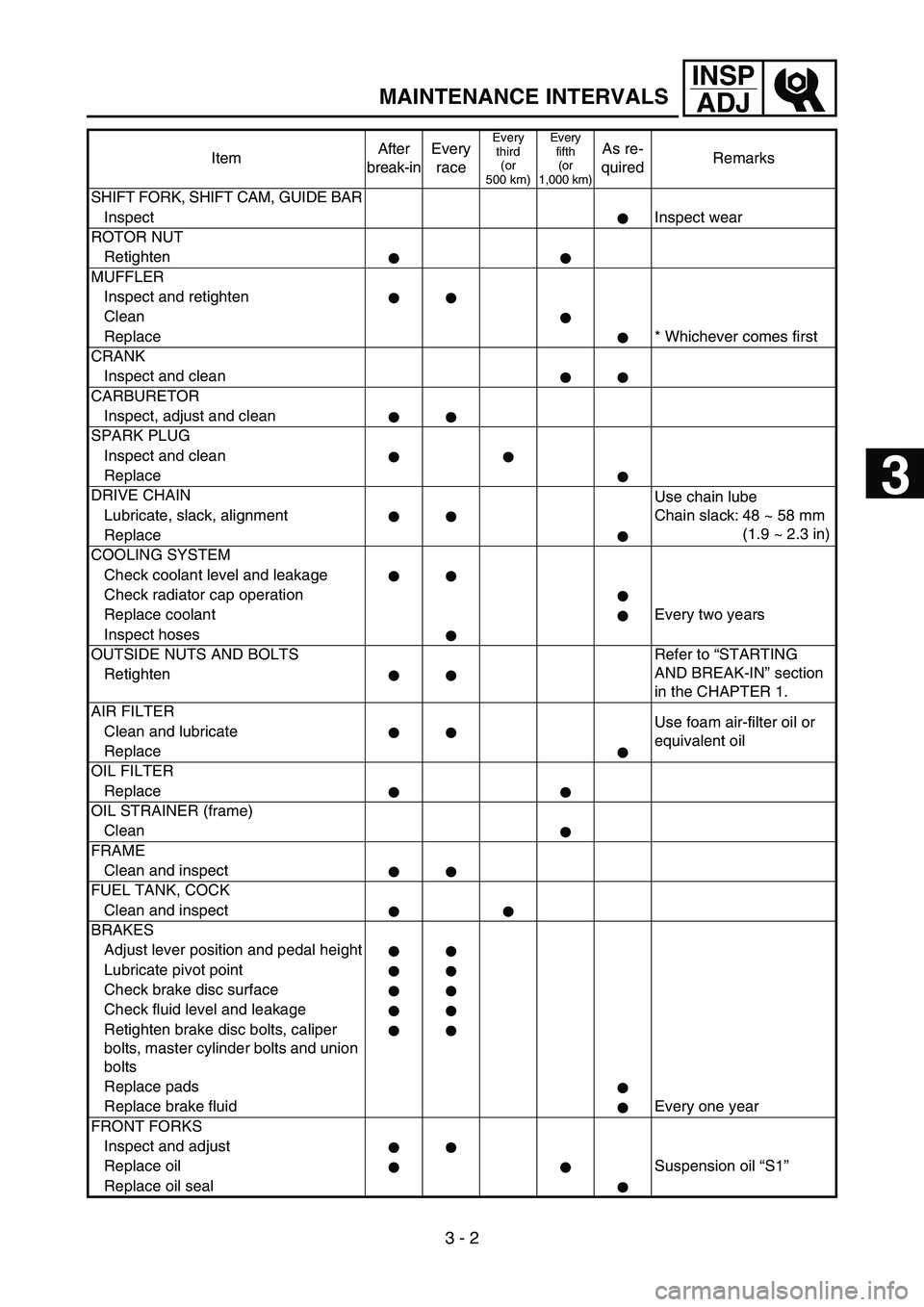
SHIFT FORK, SHIFT CAM, GUIDE BAR
InspectInspect wear
ROTOR NUT
Retighten
MUFFLER
Inspect and retighten
Clean
Replace * Whichever comes first
CRANK
Inspect and clean
CARBURETOR
Inspect, adjust and clean
SPARK PLUG
Inspect and clean
Replace
DRIVE CHAIN
Use chain lube
Chain slack: 48 ~ 58 mm
(1.9 ~ 2.3 in) Lubricate, slack, alignment
Replace
COOLING SYSTEM
Check coolant level and leakage
Check radiator cap operation
Replace coolant Every two years
Inspect hoses
OUTSIDE NUTS AND BOLTS Refer to “STARTING
AND BREAK-IN” section
in the CHAPTER 1. Retighten
AIR FILTER
Use foam air-filter oil or
equivalent oil Clean and lubricate
Replace
OIL FILTER
Replace
OIL STRAINER (frame)
Clean
FRAME
Clean and inspect
FUEL TANK, COCK
Clean and inspect
BRAKES
Adjust lever position and pedal height
Lubricate pivot point
Check brake disc surface
Check fluid level and leakage
Retighten brake disc bolts, caliper
bolts, master cylinder bolts and union
bolts
Replace pads
Replace brake fluid Every one year
FRONT FORKS
Inspect and adjust
Replace oil Suspension oil “S1”
Replace oil sealItemAfter
break-inEvery
race
Every
third
(or
500 km)Every
fifth
(or
1,000 km)As re-
quiredRemarks
3