stop start YAMAHA YZ450F 2006 Owners Manual
[x] Cancel search | Manufacturer: YAMAHA, Model Year: 2006, Model line: YZ450F, Model: YAMAHA YZ450F 2006Pages: 650, PDF Size: 20.71 MB
Page 26 of 650
GEN
INFO
1 - 1
DESCRIPTION
EC100000
GENERAL INFORMATION
EC110000
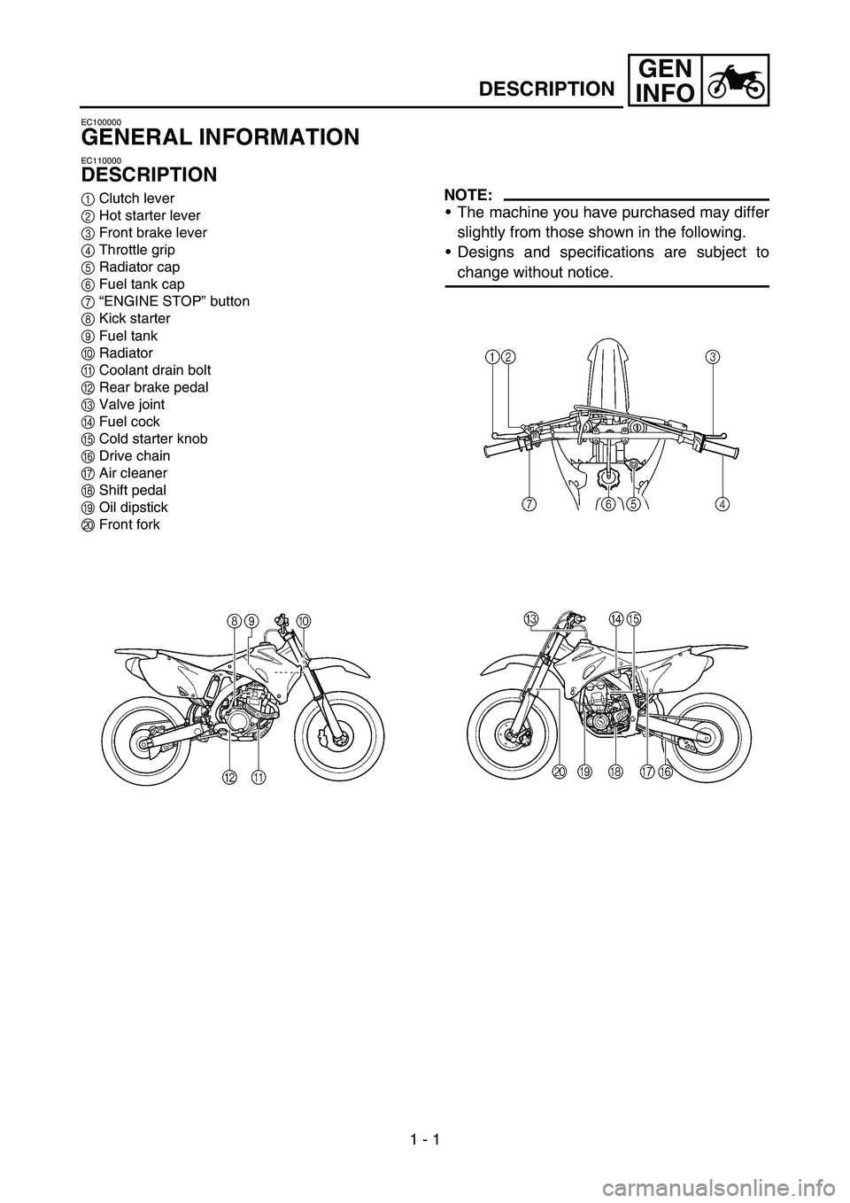
DESCRIPTION
1Clutch lever
2Hot starter lever
3Front brake lever
4Throttle grip
5Radiator cap
6Fuel tank cap
7“ENGINE STOP” button
8Kick starter
9Fuel tank
0Radiator
ACoolant drain bolt
BRear brake pedal
CValve joint
DFuel cock
ECold starter knob
FDrive chain
GAir cleaner
HShift pedal
IOil dipstick
JFront forkNOTE:
The machine you have purchased may differ
slightly from those shown in the following.
Designs and specifications are subject to
change without notice.
Page 27 of 650
GEN
INFO
ALLGEMEINE ANGABEN
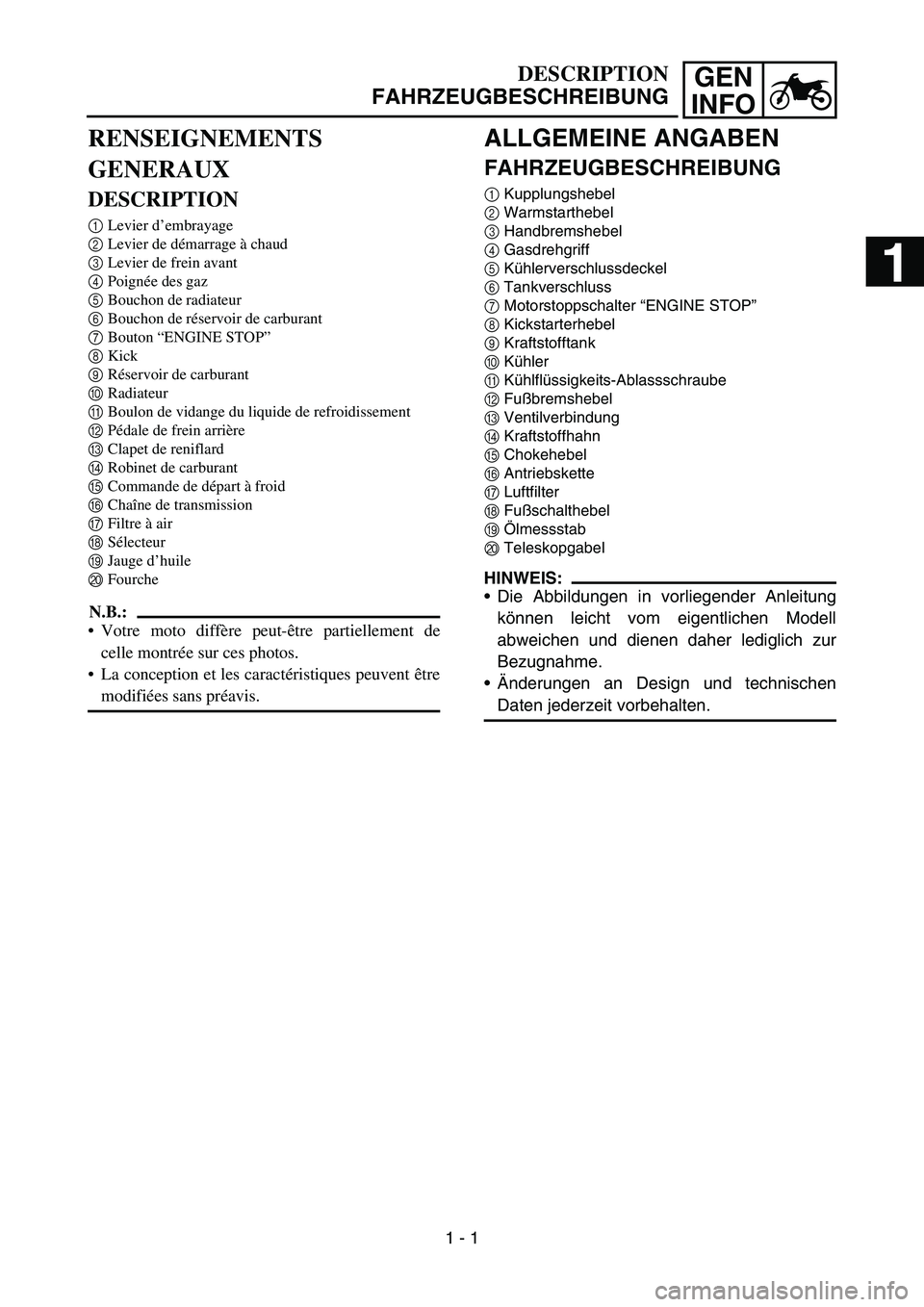
FAHRZEUGBESCHREIBUNG
1Kupplungshebel
2Warmstarthebel
3Handbremshebel
4Gasdrehgriff
5Kühlerverschlussdeckel
6Tankverschluss
7Motorstoppschalter “ENGINE STOP”
8Kickstarterhebel
9Kraftstofftank
0Kühler
AKühlflüssigkeits-Ablassschraube
BFußbremshebel
CVentilverbindung
DKraftstoffhahn
EChokehebel
FAntriebskette
GLuftfilter
HFußschalthebel
IÖlmessstab
JTeleskopgabel
HINWEIS:
Die Abbildungen in vorliegender Anleitung
können leicht vom eigentlichen Modell
abweichen und dienen daher lediglich zur
Bezugnahme.
Änderungen an Design und technischen
Daten jederzeit vorbehalten.
DESCRIPTION
FAHRZEUGBESCHREIBUNG
RENSEIGNEMENTS
GENERAUX
DESCRIPTION
1Levier d’embrayage
2Levier de démarrage à chaud
3Levier de frein avant
4Poignée des gaz
5Bouchon de radiateur
6Bouchon de réservoir de carburant
7Bouton “ENGINE STOP”
8Kick
9Réservoir de carburant
0Radiateur
ABoulon de vidange du liquide de refroidissement
BPédale de frein arrière
CClapet de reniflard
DRobinet de carburant
ECommande de départ à froid
FChaîne de transmission
GFiltre à air
HSélecteur
IJauge d’huile
JFourche
N.B.:
Votre moto diffère peut-être partiellement de
celle montrée sur ces photos.
La conception et les caractéristiques peuvent être
modifiées sans préavis.
1 - 1
1
Page 48 of 650
1 - 10
GEN
INFO
CONTROL FUNCTIONS
EC150000
CONTROL FUNCTIONS
EC151000
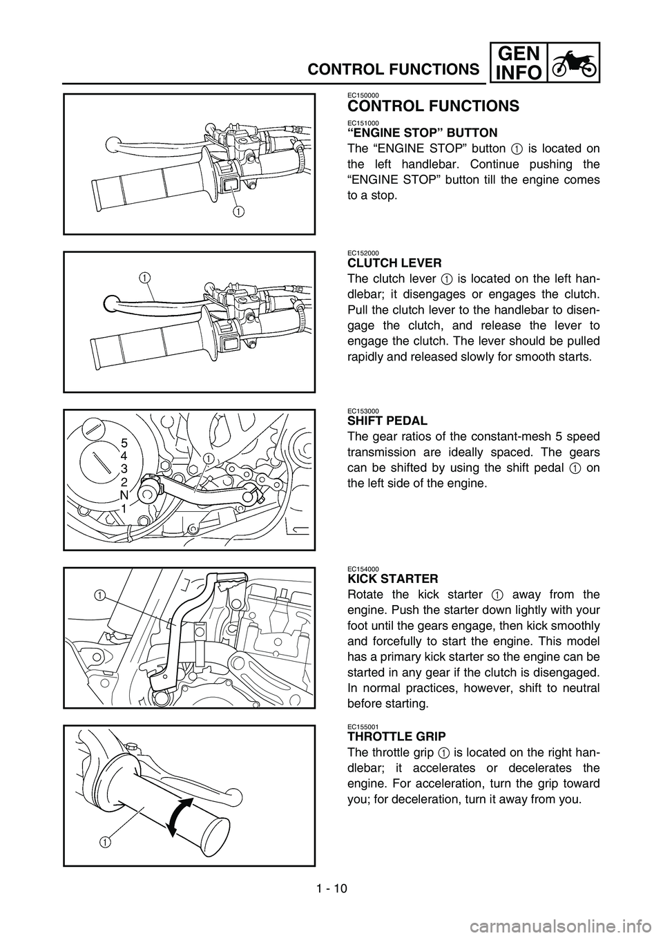
“ENGINE STOP” BUTTON
The “ENGINE STOP” button 1 is located on
the left handlebar. Continue pushing the
“ENGINE STOP” button till the engine comes
to a stop.
EC152000
CLUTCH LEVER
The clutch lever 1 is located on the left han-
dlebar; it disengages or engages the clutch.
Pull the clutch lever to the handlebar to disen-
gage the clutch, and release the lever to
engage the clutch. The lever should be pulled
rapidly and released slowly for smooth starts.
EC153000
SHIFT PEDAL
The gear ratios of the constant-mesh 5 speed
transmission are ideally spaced. The gears
can be shifted by using the shift pedal 1 on
the left side of the engine.
EC154000
KICK STARTER
Rotate the kick starter 1 away from the
engine. Push the starter down lightly with your
foot until the gears engage, then kick smoothly
and forcefully to start the engine. This model
has a primary kick starter so the engine can be
started in any gear if the clutch is disengaged.
In normal practices, however, shift to neutral
before starting.
1
EC155001
THROTTLE GRIP
The throttle grip 1 is located on the right han-
dlebar; it accelerates or decelerates the
engine. For acceleration, turn the grip toward
you; for deceleration, turn it away from you.
Page 49 of 650

GEN
INFO
BEDIENUNGSELEMENTE UND
DEREN FUNKTION
MOTORSTOPPSCHALTER “ENGINE STOP”
Der Motorstoppschalter “ENGINE STOP” 1
befindet sich links am Lenker. Den Motor-
stoppschalter “ENGINE STOP” gedrückt hal-
ten, bis der Motor stoppt.
KUPPLUNGSHEBEL
Der Kupplungshebel 1 befindet sich links am
Lenker. Zum Auskuppeln den Kupplungshe-
bel zügig ziehen, beim Einkuppeln gefühlvoll
loslassen. Dies gewährleistet ein weiches Aus-
und Einrücken der Kupplung.
FUSSCHALTHEBEL
Das 5-Gang-Getriebe dieses Motorrads ist
ideal abgestuft. Die Gänge werden über den
Fußschalthebel 1 links am Motor geschaltet.
KICKSTARTERHEBEL
Den Kickstarterhebel 1 ausklappen. Zum Anlas-
sen des Motors den Kickstarterhebel langsam
niedertreten, bis deutlicher Widerstand spürbar
wird; anschließend den Kickstarter kräftig durch-
treten. Da dieses Modell mit einem Primärkick-
starter ausgerüstet ist, kann der Motor bei
eingelegtem Gang und gezogener Kupplung
gestartet werden. Es ist jedoch ratsam, den Motor
in der Leerlaufstellung des Getriebes anzulassen.
GASDREHGRIFF
Der Gasdrehgriff 1 befindet sich rechts am
Lenker. Zum Gasgeben den Drehgriff öffnen;
zum Gaswegnehmen den Drehgriff schließen.
FONCTIONS DES COMMANDES
BEDIENUNGSELEMENTE UND DEREN FUNKTION
FONCTIONS DES COMMANDES
BOUTON “ENGINE STOP”
Le bouton “ENGINE STOP” 1 est situé sur la par-
tie gauche du guidon. Garder ce bouton enfoncé
jusqu’à ce que le moteur s’arrête.
LEVIER D’EMBRAYAGE
Le levier d’embrayage 1 est situé sur la partie gau-
che du guidon et permet d’embrayer ou de
débrayer. Tirer le levier d’embrayage vers le gui-
don pour débrayer et le relâcher pour embrayer.
Pour un démarrage en douceur, le levier doit être
tiré rapidement et relâché lentement.
SELECTEUR
Les 5 rapports de la boîte de vitesses à prise cons-
tante sont idéalement échelonnés. Le changement
de vitesse est commandé par le sélecteur 1 situé
sur le côté gauche du moteur.
KICK
Déployer le kick 1. Appuyer légèrement sur la
pédale pour mettre les pignons en prise, puis
l’actionner vigoureusement mais en souplesse pour
mettre le moteur en marche. Ce modèle est équipé
d’un kick primaire, de sorte qu’il est possible de
démarrer dans n’importe quel rapport à condition
de débrayer. Normalement, toutefois, on repassera
au point mort avant de démarrer.
POIGNEE DES GAZ
La poignée des gaz 1 est située sur la partie droite
du guidon et permet d’accélérer ou de décélérer.
Pour accélérer, tourner la poignée vers soi; pour
décélérer, la tourner dans l’autre sens.
1 - 10
Page 50 of 650
1 - 11
GEN
INFO
CONTROL FUNCTIONS
EC156000
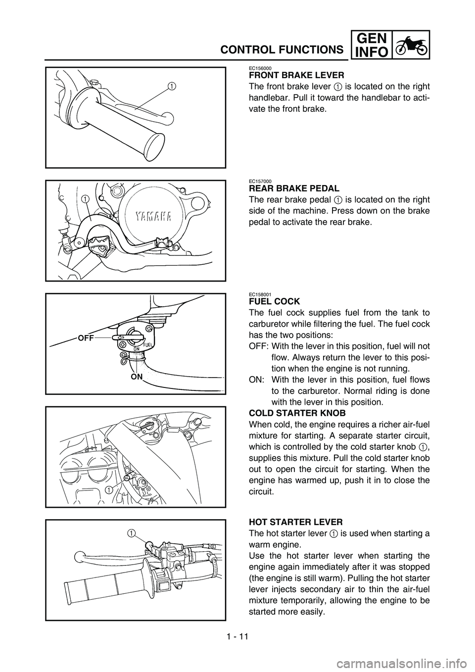
FRONT BRAKE LEVER
The front brake lever 1 is located on the right
handlebar. Pull it toward the handlebar to acti-
vate the front brake.
EC157000
REAR BRAKE PEDAL
The rear brake pedal 1 is located on the right
side of the machine. Press down on the brake
pedal to activate the rear brake.
EC158001
FUEL COCK
The fuel cock supplies fuel from the tank to
carburetor while filtering the fuel. The fuel cock
has the two positions:
OFF: With the lever in this position, fuel will not
flow. Always return the lever to this posi-
tion when the engine is not running.
ON: With the lever in this position, fuel flows
to the carburetor. Normal riding is done
with the lever in this position.
COLD STARTER KNOB
When cold, the engine requires a richer air-fuel
mixture for starting. A separate starter circuit,
which is controlled by the cold starter knob 1,
supplies this mixture. Pull the cold starter knob
out to open the circuit for starting. When the
engine has warmed up, push it in to close the
circuit.
1
HOT STARTER LEVER
The hot starter lever 1 is used when starting a
warm engine.
Use the hot starter lever when starting the
engine again immediately after it was stopped
(the engine is still warm). Pulling the hot starter
lever injects secondary air to thin the air-fuel
mixture temporarily, allowing the engine to be
started more easily.
Page 61 of 650

GEN
INFO
WARMEN MOTOR ANLASSEN
Weder den Chokehebel noch den Gasdrehgriff
betätigen. Den Warmstarthebel 1 betätigen
und den Motor mit einem festen Tritt auf dem
Kickstarterhebel anlassen.
Nach dem Anlassen des Motors den Warm-
starthebel loslassen, um die Luftzufuhr zu
stoppen.
Starten nach einem Sturz
Den Warmstarthebel betätigen und den Motor
anlassen. Nach dem Anlassen des Motors den
Warmstarthebel loslassen, um die Luftzufuhr
zu stoppen.
Wenn der Motor nicht anspringt
Den Warmstarthebel bis zum Anschlag betäti-
gen und den Kickstarterhebel 10–20 Mal
durchtreten, um den überschüssigen Kraft-
stoff aus dem Motor abzulassen.
Den Motor erneut anlassen.
Siehe unter “Starten nach einem Sturz”.
* Beim Kickstarten den Gasdrehgriff zuvor betätigen.
ACHTUNG:
Während der Einfahrzeit müssen folgende
Vorschriften strikt beachtet werden, um die
Motorleistung zu optimieren und Schäden
zu vermeiden.
Gasdreh-
griffbetäti-
gung*Chokehe-
belWarmstart-
hebel
Kalten Motor anlassen
Lufttemperatur liegt unter
5°C (41 °F)3–4 Mal
öffnenON OFF
Lufttemperatur liegt über
5°C (41 °F)Keine ON OFF
Lufttemperatur ist normal,
zwischen 5°C (41°F) und
25°C (77°F)Keine ON/OFF OFF
Lufttemperatur liegt über
25 °C (77 °F)Keine OFF OFF
Starten nach langer Einsatz-
pauseKeine ON OFF
Warmen Motor starten Keine OFF ON
Starten nach einem Sturz Keine OFF ON
MISE EN MARCHE ET RODAGE
STARTEN UND EINFAHREN
MISE EN MARCHE A CHAUD
Ne pas utiliser la commande de départ à froid ni les
gaz. Tirer le levier de démarrage à chaud 1 et
démarrer le moteur en actionnant vigoureusement
le kick d’un coup sec.
Dès que le moteur démarre, relâcher le levier de
démarrage à chaud pour fermer le passage d’air.
Redémarrage du moteur après une chute
Tirer le levier de démarrage à chaud et lancer le
moteur. Dès que le moteur démarre, relâcher le
levier de démarrage à chaud pour fermer le passage
d’air.
Le moteur ne démarre pas
Tirer à fond le levier de démarrage à chaud et, tout
en maintenant ce dernier, actionner 10 à 20 fois le
kick pour purger le moteur.
Redémarrer ensuite le moteur.
Se reporter à “Redémarrage du moteur après une
chute”.
* Actionner la poignée des gaz avant d’actionner le kick.
ATTENTION:
Afin d’éviter d’endommager le moteur et assu-
rer le meilleur rendement possible, il convient de
roder la moto de la manière expliquée ci-après.
Utilisation
de la poi-
gnée des
gaz*Com-
mande de
départ à
froidLevier de
démarrage
à chaud
Démarrage d’un moteur froid
Température de l’air = infé-
rieure à 5 °C (41 °F)Ouvrir 3 à
quatre foisON OFF
Température de l’air = supé-
rieure à 5 °C (41 °F)Aucune ON OFF
Température de l’air (tempéra-
ture normale) = entre 5°C
(41°F) et 25°C (77°F)Aucune ON/OFF OFF
Température de l’air = supé-
rieure à 25 °C (77 °F)Aucune OFF OFF
Démarrage du moteur après une
longue périodeAucune ON OFF
Redémarrage d’un moteur chaud Aucune OFF ON
Redémarrage du moteur après une
chuteAucune OFF ON
1 - 16
Page 62 of 650

1 - 17
GEN
INFO
BREAK-IN PROCEDURES
1. Before starting the engine, fill the fuel tank
with the fuel.
2. Perform the pre-operation checks on the
machine.
3. Start and warm up the engine. Check the
idle speed, and check the operation of the
controls and the “ENGINE STOP” button.
Then, restart the engine and check its
operation within no more than 5 minutes
after it is restarted.
4. Operate the machine in the lower gears at
moderate throttle openings for five to eight
minutes.
5. Check how the engine runs when the
machine is ridden with the throttle 1/4 to 1/2
open (low to medium speed) for about one
hour.
6. Restart the engine and check the operation
of the machine throughout its entire operat-
ing range. Restart the machine and oper-
ate it for about 10 to 15 more minutes. The
machine will now be ready to race.
CAUTION:
After the break-in or before each race,
you must check the entire machine for
loose fittings and fasteners as per
“TORQUE-CHECK POINTS”.
Tighten all such fasteners as required.
When any of the following parts have
been replaced, they must be broken in.
CYLINDER AND CRANKSHAFT:
About one hour of break-in operation is
necessary.
PISTON, RING, VALVES, CAMSHAFTS
AND GEARS:
These parts require about 30 minutes of
break-in operation at half-throttle or less.
Observe the condition of the engine care-
fully during operation.
STARTING AND BREAK-IN
Page 63 of 650

GEN
INFO
EINFAHRVORSCHRIFTEN
1. Vor dem Starten voll tanken.
2. Die “Routinekontrolle vor Fahrtbeginn” aus-
führen.
3. Den Motor anlassen und einige Minuten
lang betreiben. Die Leerlaufdrehzahl und
die Funktion der Bedienelemente ein-
schließlich des Motorstoppschalters
“ENGINE STOP” kontrollieren. Den Motor
erneut anlassen und innerhalb 5 Minuten
dessen Funktion kontrollieren.
4. Die Maschine 5–8 Minuten lang mit mäßi-
gem Gas im unteren Gangbereich betrei-
ben.
5. Den Motorbetrieb bei 1/4 bis 1/2 geöffne-
tem Gasdrehgriff (niedriger bis mäßiger
Geschwindigkeit) etwa eine Stunde lang
überwachen.
6. Den Motor erneut starten und den gesam-
ten Betriebsbereich kontrollieren. Den
Motor erneut starten und weiter 10–15
Minuten lang betreiben. Die Maschine ist
nun rennfertig.
ACHTUNG:
Entsprechend dem Abschnitt “ANZUGS-
DREHMOMENTE KONTROLLIEREN”,
nach dem Einfahren sowie vor jedem
Rennen sämtliche Befestigungselemente
kontrollieren.
Befestigungselemente ggf. vorschrifts-
mäßig festziehen.
Folgende Bauteile müssen nach dem
Auswechseln eingefahren werden.
ZYLINDER UND KURBELWELLE:
Eine einstündige Einfahrzeit einlegen.
KOLBEN, KOLBENRINGE, VENTILE,
NOCKLENWELLEN UND RITZEL:
Eine halbstündige Einfahrzeit mit maxi-
mal halb geöffnetem Gasdrehgriff einle-
gen. Den Motorbetrieb gründlich
überwachen.
MISE EN MARCHE ET RODAGE
STARTEN UND EINFAHREN
PROCEDURE DE RODAGE
1. Avant de démarrer le moteur, faire le plein du
réservoir de carburant.
2. Effectuer les contrôles avant utilisation.
3. Mettre le moteur en marche et le laisser chauf-
fer. Contrôler le régime de ralenti et le bon
fonctionnement des commandes et du bouton
“ENGINE STOP”. Redémarrer ensuite le
moteur et contrôler son fonctionnement dans
les 5 minutes maximum qui suivent son redé-
marrage.
4. Rouler pendant cinq à huit minutes sur les rap-
ports inférieurs et à régime modéré.
5. Contrôler le fonctionnement du moteur lorsque
la moto est utilisée pendant une heure environ
aux régimes bas à moyens (ouverture des gaz
1/4 à 1/2).
6. Remettre le moteur en marche et vérifier le
fonctionnement de la moto à toutes les vitesses.
Redémarrer la moto et rouler pendant 10 à 15
minutes environ. La moto est maintenant prête
pour la course.
ATTENTION:
Après le rodage ou avant chaque course, il est
indispensable de contrôler le bon serrage des
raccords et des fixations conformément aux
instructions de la section “POINTS DE VERI-
FICATION DES COUPLES DE SERRAGE”.
Resserrer au couple requis tout élément des-
serré.
Si l’une quelconque des pièces suivantes a été
remplacée, un nouveau rodage est nécessaire.
CYLINDRE ET VILEBREQUIN:
Roder pendant environ une heure.
PISTON, SEGMENT, SOUPAPES, ARBRES
A CAMES ET PIGNONS:
Ces pièces nécessitent un rodage d’environ 30
minutes à une ouverture des gaz de 1/2 au
maximum. Surveiller attentivement l’état du
moteur pendant le rodage.
1 - 17
Page 70 of 650

1 - 20
GEN
INFO
CLEANING AND STORAGE
8. Automotive wax may be applied to all
painted or chromed surfaces. Avoid combi-
nation cleaner-waxes, as they may contain
abrasives.
9. After completing the above, start the
engine and allow it to idle for several min-
utes.
EC1B2001
STORAGE
If your machine is to be stored for 60 days or
more, some preventive measures must be
taken to avoid deterioration. After cleaning the
machine thoroughly, prepare it for storage as
follows:
1. Drain the fuel tank, fuel lines, and the car-
buretor float bowl.
2. Remove the spark plug, pour a tablespoon
of SAE 10W-30 motor oil in the spark plug
hole, and reinstall the plug. With the engine
stop switch pushed in, kick the engine over
several times to coat the cylinder walls with
oil.
3. Remove the drive chain, clean it thoroughly
with solvent, and lubricate it. Reinstall the
chain or store it in a plastic bag tied to the
frame.
4. Lubricate all control cables.
5. Block the frame up to raise the wheels off
the ground.
6. Tie a plastic bag over the exhaust pipe out-
let to prevent moisture from entering.
7. If the machine is to be stored in a humid or
salt-air environment, coat all exposed
metal surfaces with a film of light oil. Do not
apply oil to rubber parts or the seat cover.
NOTE:
Make any necessary repairs before the
machine is stored.
Page 71 of 650
GEN
INFO
8. Alle lackierten und verchromten Oberflä-
chen mit Pflegewachs behandeln. Keine
Pflegemittel mit Scheurmitteln verwenden,
um Kratzer zu vermeiden.
9. Anschließend den Motor anlassen und
einige Minuten lang betreiben.
LAGERUNG
Soll das Motorrad länger als 60 Tage gelagert
werden, sind gewisse Schutzmaßnahmen not-
wendig. Das Motorrad nach der Wäsche, wie
nachfolgend beschrieben, auf die Lagerung
vorbereiten:
1. Das Benzin aus dem Kraftstofftank ablas-
sen und den Vergaser entleeren.
2. Die Zündkerze herausdrehen, einen Ess-
löffel SAE 10W-30-Motoröl in die Zündker-
zenbohrung gießen und die Zündkerze
wieder eindrehen. Bei betätigtem Motor-
stoppschalter mehrmals den Kickstarterhe-
bel durchtreten, um die
Zylinderwandungen mit Öl zu bedecken.
3. Die Antriebskette abnehmen, gründlich rei-
nigen und anschließend schmieren. Die
Kette montieren oder in einem am Rahmen
angebundenen Plastikbeutel aufbewahren.
4. Sämtliche Seilzüge ölen.
5. Das Motorrad so abstützen, dass die
Räder sich frei drehen lassen.
6. Einen Plastikbeutel über die Schalldämp-
feröffnung binden, damit keine Feuchtigkeit
eindringt.
7. Ist der Lagerort feucht oder salzhaltig,
sämtliche Metallflächen mit Sprühöl behan-
deln. Öl von Gummiteilen und der Sitzbank
fern halten.
HINWEIS:
Anfallende Reparaturen oder Inspektion vor
der Stilllegung ausführen.
NETTOYAGE ET REMISAGE
PFLEGE UND LAGERUNG
8. Une cire pour carrosserie peut être utilisée pour
toutes les surfaces peintes et chromées. Ne pas
employer de cires détergentes car elles contien-
nent souvent des abrasifs.
9. Lorsque le nettoyage est terminé, mettre le
moteur en marche et le laisser tourner au ralenti
pendant plusieurs minutes.
REMISAGE
Si la moto doit être remisée pour 60 jours ou plus, il
convient de prendre certaines précautions pour évi-
ter tout endommagement. Après un nettoyage com-
plet de la moto, la préparer comme suit pour le
remisage:
1. Vidanger le réservoir de carburant, le circuit de
carburant et la cuve à niveau constant du carbu-
rateur.
2. Déposer la bougie, verser une cuillère à soupe
d’huile moteur SAE 10W-30 dans le trou de
bougie et replacer la bougie. Enfoncer le coupe-
circuit du moteur et lancer quelques fois le
moteur à l’aide du kick afin de répartir l’huile
sur les parois du cylindre.
3. Déposer la chaîne de transmission, la nettoyer
soigneusement à l’aide d’un solvant puis la
graisser. Remettre en place la chaîne ou la con-
server dans un sachet en plastique (attaché au
cadre pour éviter de l’égarer).
4. Lubrifier tous les câbles de commande.
5. Placer un support sous le cadre afin de suréle-
ver les deux roues.
6. Couvrir la sortie du tuyau d’échappement d’un
sachet en plastique pour empêcher la pénétra-
tion d’humidité.
7. Si la moto doit être remisée dans un lieu très
humide ou exposé à l’air marin, enduire toutes
les surfaces métalliques extérieures d’une fine
couche d’huile. Ne pas enduire d’huile les par-
ties en caoutchouc et la housse de selle.
N.B.:
Effectuer toutes les réparations nécessaires avant de
remiser la moto.
1 - 20