water pump YAMAHA YZ450F 2008 Owners Manual
[x] Cancel search | Manufacturer: YAMAHA, Model Year: 2008, Model line: YZ450F, Model: YAMAHA YZ450F 2008Pages: 188, PDF Size: 11.75 MB
Page 10 of 188
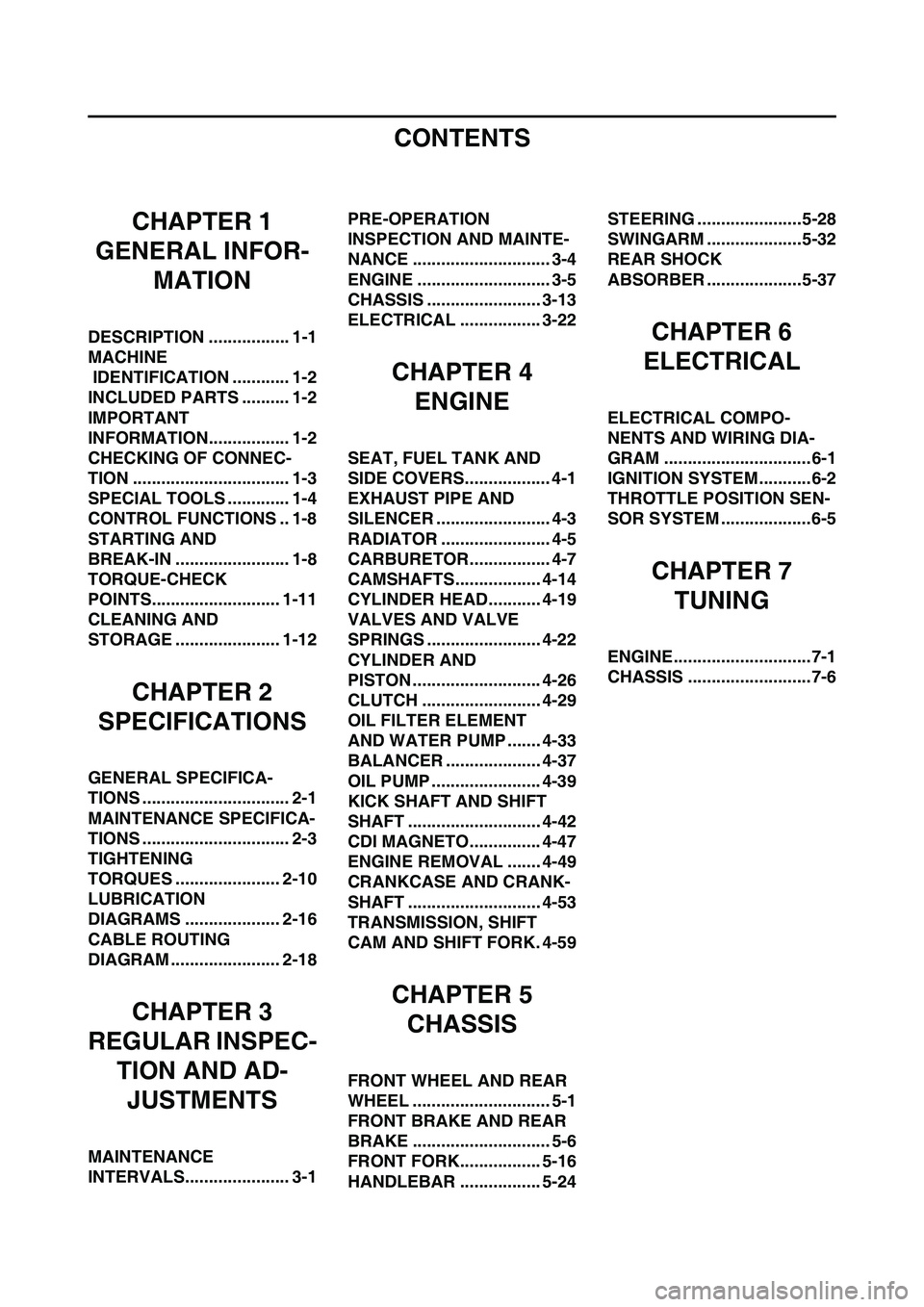
CONTENTS
CHAPTER 1
GENERAL INFOR-
MATION
DESCRIPTION ................. 1-1
MACHINE
IDENTIFICATION ............ 1-2
INCLUDED PARTS .......... 1-2
IMPORTANT
INFORMATION................. 1-2
CHECKING OF CONNEC-
TION ................................. 1-3
SPECIAL TOOLS ............. 1-4
CONTROL FUNCTIONS .. 1-8
STARTING AND
BREAK-IN ........................ 1-8
TORQUE-CHECK
POINTS........................... 1-11
CLEANING AND
STORAGE ...................... 1-12
CHAPTER 2
SPECIFICATIONS
GENERAL SPECIFICA-
TIONS ............................... 2-1
MAINTENANCE SPECIFICA-
TIONS ............................... 2-3
TIGHTENING
TORQUES ...................... 2-10
LUBRICATION
DIAGRAMS .................... 2-16
CABLE ROUTING
DIAGRAM ....................... 2-18
CHAPTER 3
REGULAR INSPEC-
TION AND AD-
JUSTMENTS
MAINTENANCE
INTERVALS...................... 3-1PRE-OPERATION
INSPECTION AND MAINTE-
NANCE ............................. 3-4
ENGINE ............................ 3-5
CHASSIS ........................ 3-13
ELECTRICAL ................. 3-22
CHAPTER 4
ENGINE
SEAT, FUEL TANK AND
SIDE COVERS.................. 4-1
EXHAUST PIPE AND
SILENCER ........................ 4-3
RADIATOR ....................... 4-5
CARBURETOR................. 4-7
CAMSHAFTS.................. 4-14
CYLINDER HEAD........... 4-19
VALVES AND VALVE
SPRINGS ........................ 4-22
CYLINDER AND
PISTON ........................... 4-26
CLUTCH ......................... 4-29
OIL FILTER ELEMENT
AND WATER PUMP ....... 4-33
BALANCER .................... 4-37
OIL PUMP ....................... 4-39
KICK SHAFT AND SHIFT
SHAFT ............................ 4-42
CDI MAGNETO............... 4-47
ENGINE REMOVAL ....... 4-49
CRANKCASE AND CRANK-
SHAFT ............................ 4-53
TRANSMISSION, SHIFT
CAM AND SHIFT FORK. 4-59
CHAPTER 5
CHASSIS
FRONT WHEEL AND REAR
WHEEL ............................. 5-1
FRONT BRAKE AND REAR
BRAKE ............................. 5-6
FRONT FORK................. 5-16
HANDLEBAR ................. 5-24STEERING ......................5-28
SWINGARM ....................5-32
REAR SHOCK
ABSORBER ....................5-37
CHAPTER 6
ELECTRICAL
ELECTRICAL COMPO-
NENTS AND WIRING DIA-
GRAM ...............................6-1
IGNITION SYSTEM...........6-2
THROTTLE POSITION SEN-
SOR SYSTEM ...................6-5
CHAPTER 7
TUNING
ENGINE.............................7-1
CHASSIS ..........................7-6
Page 12 of 188
1-2
MACHINE IDENTIFICATION
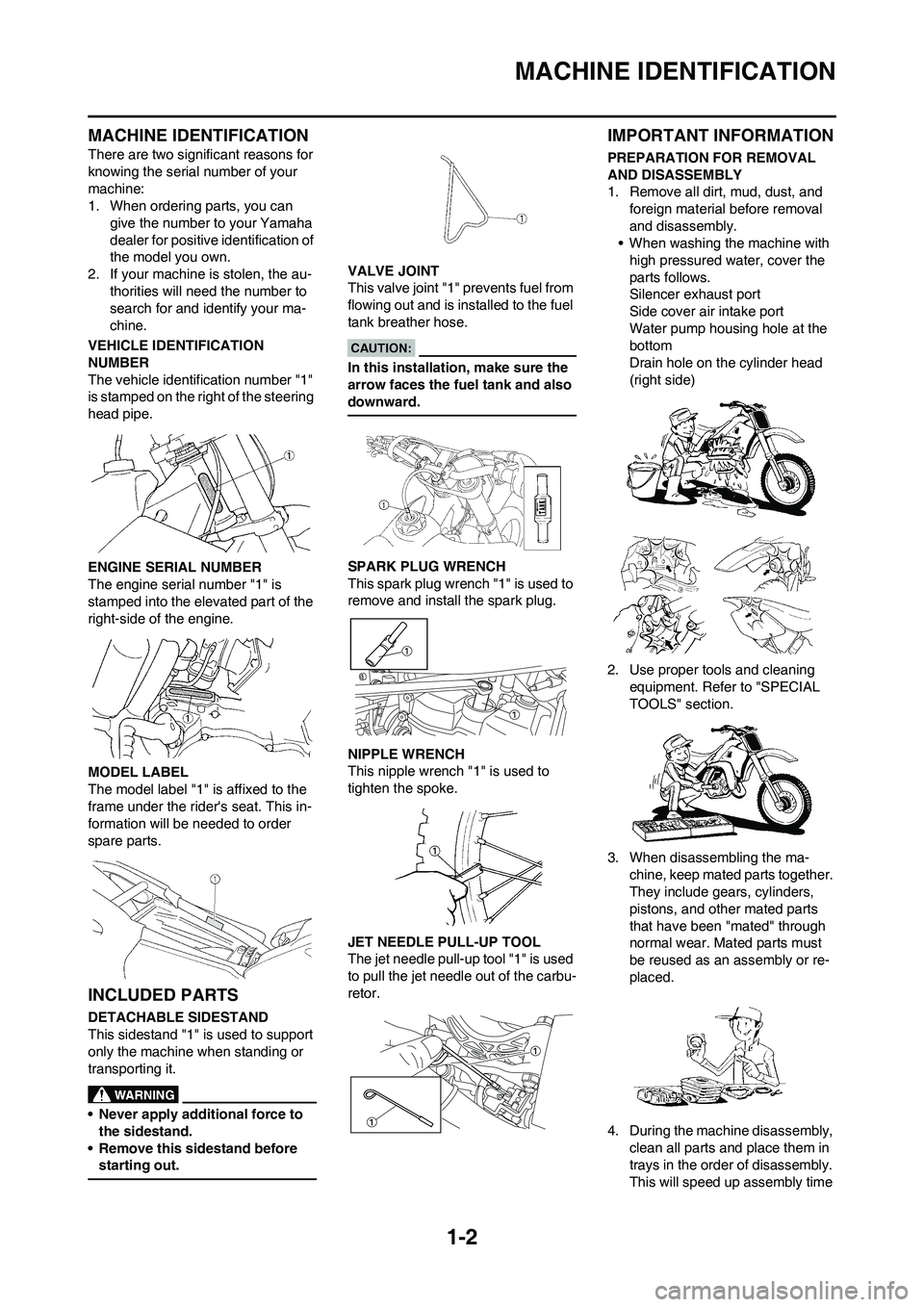
MACHINE IDENTIFICATION
There are two significant reasons for
knowing the serial number of your
machine:
1. When ordering parts, you can
give the number to your Yamaha
dealer for positive identification of
the model you own.
2. If your machine is stolen, the au-
thorities will need the number to
search for and identify your ma-
chine.
VEHICLE IDENTIFICATION
NUMBER
The vehicle identification number "1"
is stamped on the right of the steering
head pipe.
ENGINE SERIAL NUMBER
The engine serial number "1" is
stamped into the elevated part of the
right-side of the engine.
MODEL LABEL
The model label "1" is affixed to the
frame under the rider's seat. This in-
formation will be needed to order
spare parts.
INCLUDED PARTS
DETACHABLE SIDESTAND
This sidestand "1" is used to support
only the machine when standing or
transporting it.
• Never apply additional force to
the sidestand.
• Remove this sidestand before
starting out.
VALVE JOINT
This valve joint "1" prevents fuel from
flowing out and is installed to the fuel
tank breather hose.
In this installation, make sure the
arrow faces the fuel tank and also
downward.
SPARK PLUG WRENCH
This spark plug wrench "1" is used to
remove and install the spark plug.
NIPPLE WRENCH
This nipple wrench "1" is used to
tighten the spoke.
JET NEEDLE PULL-UP TOOL
The jet needle pull-up tool "1" is used
to pull the jet needle out of the carbu-
retor.
IMPORTANT INFORMATION
PREPARATION FOR REMOVAL
AND DISASSEMBLY
1. Remove all dirt, mud, dust, and
foreign material before removal
and disassembly.
• When washing the machine with
high pressured water, cover the
parts follows.
Silencer exhaust port
Side cover air intake port
Water pump housing hole at the
bottom
Drain hole on the cylinder head
(right side)
2. Use proper tools and cleaning
equipment. Refer to "SPECIAL
TOOLS" section.
3. When disassembling the ma-
chine, keep mated parts together.
They include gears, cylinders,
pistons, and other mated parts
that have been "mated" through
normal wear. Mated parts must
be reused as an assembly or re-
placed.
4. During the machine disassembly,
clean all parts and place them in
trays in the order of disassembly.
This will speed up assembly time
Page 30 of 188
2-8
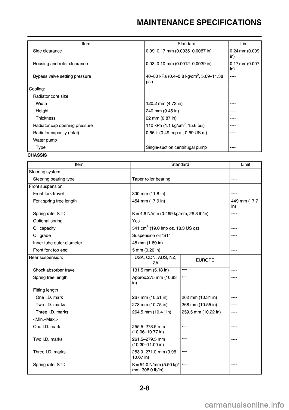
MAINTENANCE SPECIFICATIONS
CHASSISSide clearance 0.09–0.17 mm (0.0035–0.0067 in) 0.24 mm (0.009
in)
Housing and rotor clearance 0.03–0.10 mm (0.0012–0.0039 in) 0.17 mm (0.007
in)
Bypass valve setting pressure 40–80 kPa (0.4–0.8 kg/cm
2, 5.69–11.38
psi)----
Cooling:
Radiator core size
Width 120.2 mm (4.73 in) ----
Height 240 mm (9.45 in) ----
Thickness 22 mm (0.87 in) ----
Radiator cap opening pressure 110 kPa (1.1 kg/cm
2, 15.6 psi) ----
Radiator capacity (total) 0.56 L (0.49 Imp qt, 0.59 US qt) ----
Water pump
Type Single-suction centrifugal pump ----Item Standard Limit
Item Standard Limit
Steering system:
Steering bearing typeTaper roller bearing ----
Front suspension:
Front fork travel 300 mm (11.8 in) ----
Fork spring free length 454 mm (17.9 in) 449 mm (17.7
in)
Spring rate, STD K = 4.6 N/mm (0.469 kg/mm, 26.3 lb/in) ----
Optional spring Yes ----
Oil capacity 541 cm
3 (19.0 lmp oz, 18.3 US oz) ----
Oil grade Suspension oil "S1" ----
Inner tube outer diameter 48 mm (1.89 in) ----
Front fork top end 5 mm (0.20 in) ----
Rear suspension: USA, CDN, AUS, NZ,
ZAEUROPE
Shock absorber travel 131.5 mm (5.18 in)
←----
Spring free length Approx.275 mm (10.83
in)
←----
Fitting length
One I.D. mark 267 mm (10.51 in) 262 mm (10.31 in) ----
Two I.D. marks 273 mm (10.75 in) 268 mm (10.55 in) ----
Three I.D. marks 264.5 mm (10.41 in) 259.5 mm (10.22 in) ----
One I.D. mark 255.5–273.5 mm
(10.06–10.77 in)
←----
Two I.D. marks 261.5–279.5 mm
(10.30–11.00 in)
←----
Three I.D. marks 253.0–271.0 mm (9.96–
10.67 in)
←----
Spring rate, STD K = 54.0 N/mm (5.50 kg/
mm, 308.0 lb/in)
←----
Page 33 of 188
2-11
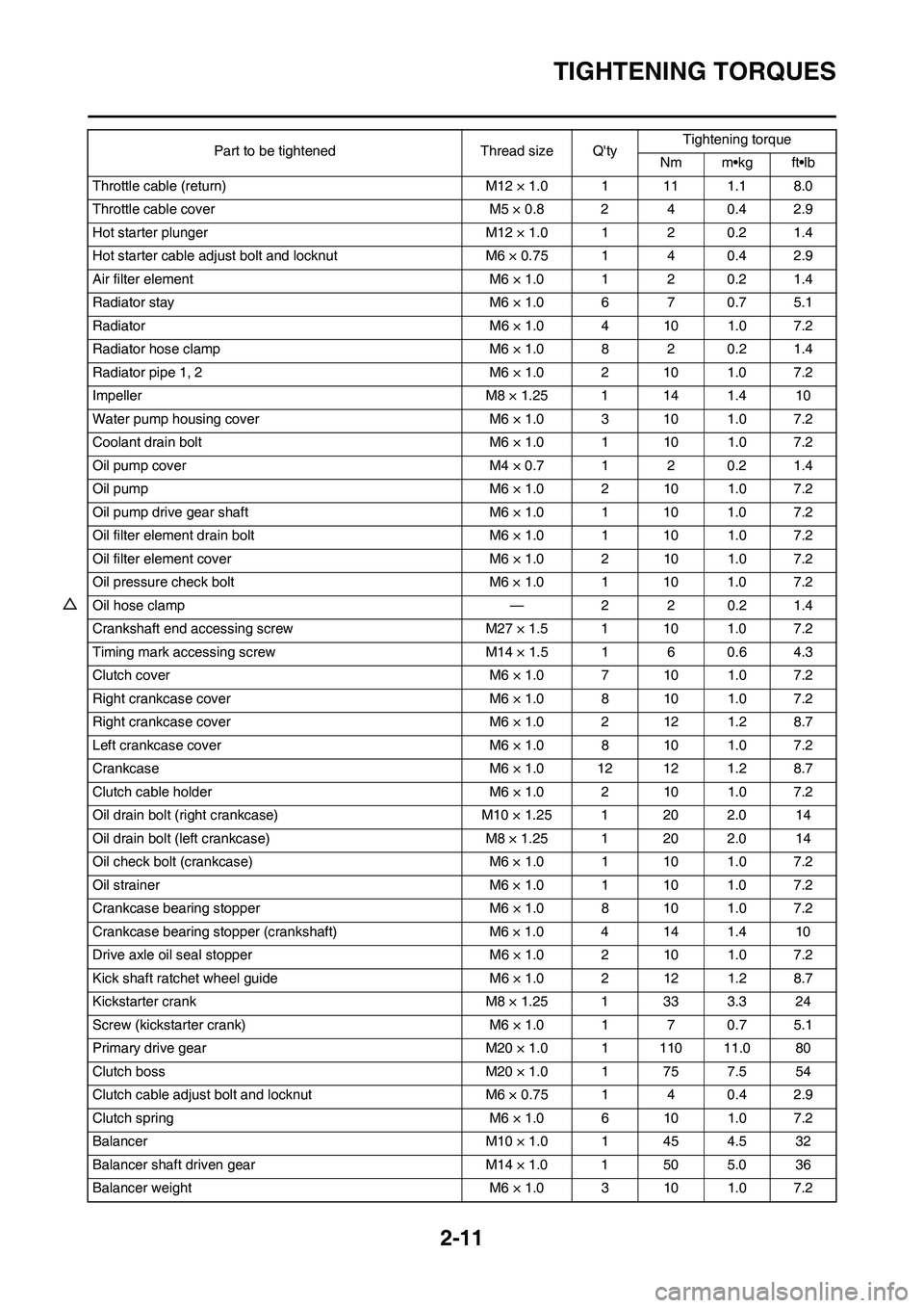
TIGHTENING TORQUES
Throttle cable (return) M12 × 1.0 1 11 1.1 8.0
Throttle cable cover M5 × 0.8 2 4 0.4 2.9
Hot starter plunger M12 × 1.0 1 2 0.2 1.4
Hot starter cable adjust bolt and locknut M6 × 0.75 1 4 0.4 2.9
Air filter element M6 × 1.0 1 2 0.2 1.4
Radiator stay M6 × 1.0 6 7 0.7 5.1
Radiator M6 × 1.0 4 10 1.0 7.2
Radiator hose clamp M6 × 1.0 8 2 0.2 1.4
Radiator pipe 1, 2 M6 × 1.0 2 10 1.0 7.2
Impeller M8 × 1.25 1 14 1.4 10
Water pump housing cover M6 × 1.0 3 10 1.0 7.2
Coolant drain bolt M6 × 1.0 1 10 1.0 7.2
Oil pump cover M4 × 0.7 1 2 0.2 1.4
Oil pump M6 × 1.0 2 10 1.0 7.2
Oil pump drive gear shaft M6 × 1.0 1 10 1.0 7.2
Oil filter element drain bolt M6 × 1.0 1 10 1.0 7.2
Oil filter element cover M6 × 1.0 2 10 1.0 7.2
Oil pressure check bolt M6 × 1.0 1 10 1.0 7.2
△Oil hose clamp — 2 2 0.2 1.4
Crankshaft end accessing screw M27 × 1.5 1 10 1.0 7.2
Timing mark accessing screw M14 × 1.5 1 6 0.6 4.3
Clutch cover M6 × 1.0 7 10 1.0 7.2
Right crankcase cover M6 × 1.0 8 10 1.0 7.2
Right crankcase cover M6 × 1.0 2 12 1.2 8.7
Left crankcase cover M6 × 1.0 8 10 1.0 7.2
Crankcase M6 × 1.0 12 12 1.2 8.7
Clutch cable holder M6 × 1.0 2 10 1.0 7.2
Oil drain bolt (right crankcase) M10 × 1.25 1 20 2.0 14
Oil drain bolt (left crankcase) M8 × 1.25 1 20 2.0 14
Oil check bolt (crankcase) M6 × 1.0 1 10 1.0 7.2
Oil strainer M6 × 1.0 1 10 1.0 7.2
Crankcase bearing stopper M6 × 1.0 8 10 1.0 7.2
Crankcase bearing stopper (crankshaft) M6 × 1.0 4 14 1.4 10
Drive axle oil seal stopper M6 × 1.0 2 10 1.0 7.2
Kick shaft ratchet wheel guide M6 × 1.0 2 12 1.2 8.7
Kickstarter crank M8 × 1.25 1 33 3.3 24
Screw (kickstarter crank) M6 × 1.0 1 7 0.7 5.1
Primary drive gear M20 × 1.0 1 110 11.0 80
Clutch boss M20 × 1.0 1 75 7.5 54
Clutch cable adjust bolt and locknut M6 × 0.75 1 4 0.4 2.9
Clutch spring M6 × 1.0 6 10 1.0 7.2
Balancer M10 × 1.0 1 45 4.5 32
Balancer shaft driven gear M14 × 1.0 1 50 5.0 36
Balancer weight M6 × 1.0 3 10 1.0 7.2Part to be tightened Thread size Q'tyTightening torque
Nm m•kg ft•lb
Page 101 of 188
4-33
OIL FILTER ELEMENT AND WATER PUMP
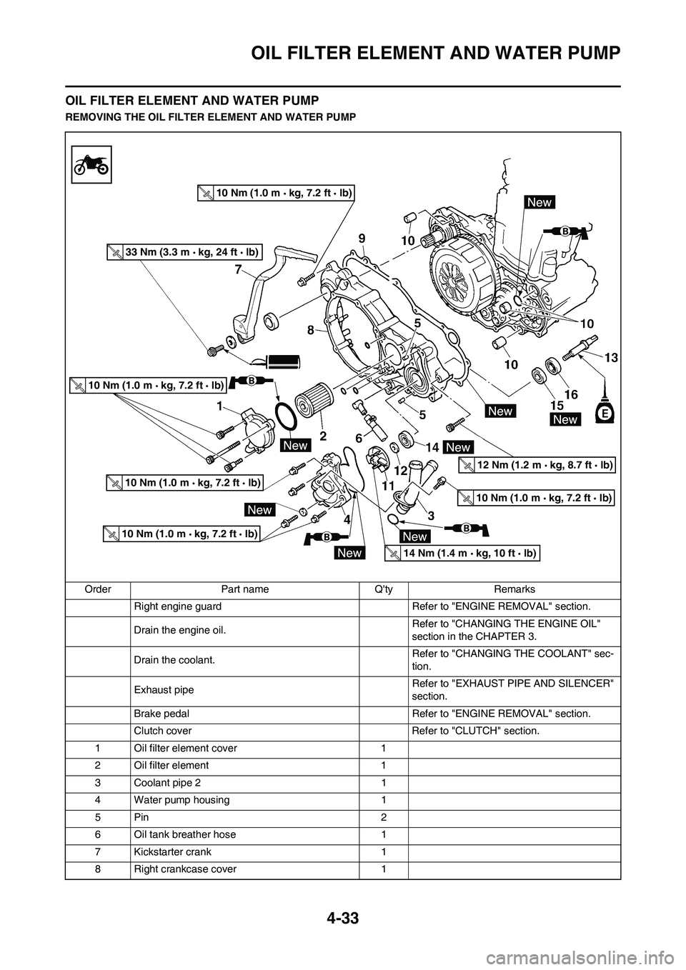
OIL FILTER ELEMENT AND WATER PUMP
REMOVING THE OIL FILTER ELEMENT AND WATER PUMP
Order Part name Q'ty Remarks
Right engine guard Refer to "ENGINE REMOVAL" section.
Drain the engine oil. Refer to "CHANGING THE ENGINE OIL"
section in the CHAPTER 3.
Drain the coolant. Refer to "CHANGING THE COOLANT" sec-
tion.
Exhaust pipe Refer to "EXHAUST PIPE AND SILENCER"
section.
Brake pedal Refer to "ENGINE REMOVAL" section.
Clutch cover Refer to "CLUTCH" section.
1 Oil filter element cover 1
2 Oil filter element 1
3 Coolant pipe 2 1
4 Water pump housing 1
5Pin 2
6 Oil tank breather hose 1
7 Kickstarter crank 1
8 Right crankcase cover 1
10 Nm (1.0 m kg, 7.2 ft lb)
10 Nm (1.0 m kg, 7.2 ft lb)
10 Nm (1.0 m kg, 7.2 ft lb)
10 Nm (1.0 m kg, 7.2 ft lb)
10 Nm (1.0 m kg, 7.2 ft lb)
33 Nm (3.3 m kg, 24 ft lb)
14 Nm (1.4 m kg, 10 ft lb)
12 Nm (1.2 m kg, 8.7 ft lb)
Page 102 of 188
4-34
OIL FILTER ELEMENT AND WATER PUMP
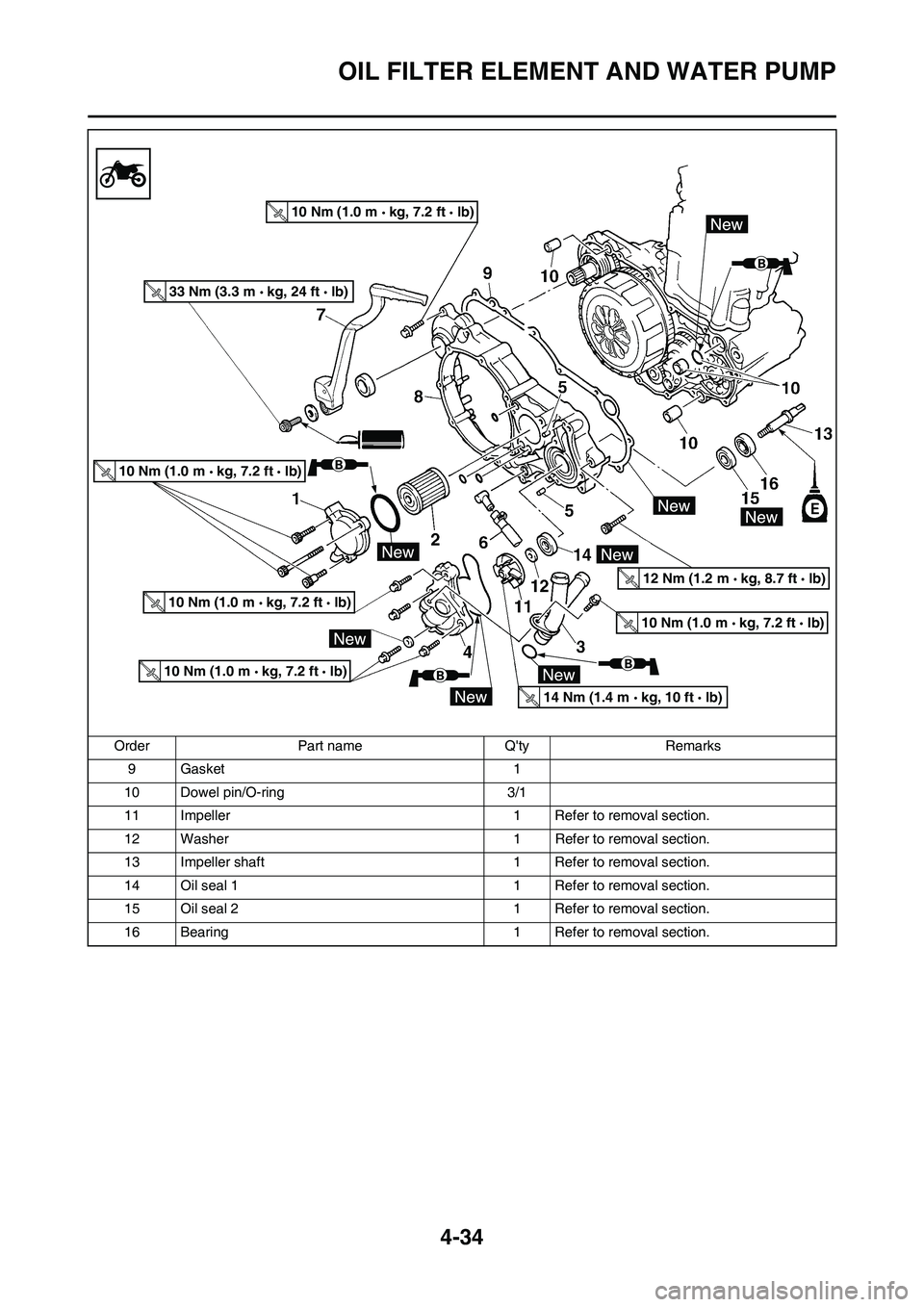
9 Gasket 1
10 Dowel pin/O-ring 3/1
11 Impeller 1 Refer to removal section.
12 Washer 1 Refer to removal section.
13 Impeller shaft 1 Refer to removal section.
14 Oil seal 1 1 Refer to removal section.
15 Oil seal 2 1 Refer to removal section.
16 Bearing 1 Refer to removal section. Order Part name Q'ty Remarks
10 Nm (1.0 m kg, 7.2 ft lb)
10 Nm (1.0 m kg, 7.2 ft lb)
10 Nm (1.0 m kg, 7.2 ft lb)
10 Nm (1.0 m kg, 7.2 ft lb)
10 Nm (1.0 m kg, 7.2 ft lb)
33 Nm (3.3 m kg, 24 ft lb)
14 Nm (1.4 m kg, 10 ft lb)
12 Nm (1.2 m kg, 8.7 ft lb)
Page 103 of 188
4-35
OIL FILTER ELEMENT AND WATER PUMP
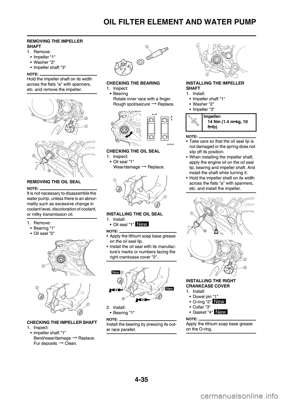
REMOVING THE IMPELLER
SHAFT
1. Remove:
• Impeller "1"
• Washer "2"
• Impeller shaft "3"
Hold the impeller shaft on its width
across the flats "a" with spanners,
etc. and remove the impeller.
REMOVING THE OIL SEAL
It is not necessary to disassemble the
water pump, unless there is an abnor-
mality such as excessive change in
coolant level, discoloration of coolant,
or milky transmission oil.
1. Remove:
• Bearing "1"
• Oil seal "2"
CHECKING THE IMPELLER SHAFT
1. Inspect:
• Impeller shaft "1"
Bend/wear/damage
→Replace.
Fur deposits
→Clean.CHECKING THE BEARING
1. Inspect:
•Bearing
Rotate inner race with a finger.
Rough spot/seizure
→Replace.
CHECKING THE OIL SEAL
1. Inspect:
• Oil seal "1"
Wear/damage
→Replace.
INSTALLING THE OIL SEAL
1. Install:
• Oil seal "1"
• Apply the lithium soap base grease
on the oil seal lip.
• Install the oil seal with its manufac-
ture's marks or numbers facing the
right crankcase cover "2".
2. Install:
•Bearing "1"
Install the bearing by pressing its out-
er race parallel.
INSTALLING THE IMPELLER
SHAFT
1. Install:
• Impeller shaft "1"
• Washer "2"
• Impeller "3"
• Take care so that the oil seal lip is
not damaged or the spring does not
slip off its position.
• When installing the impeller shaft,
apply the engine oil on the oil seal
lip, bearing and impeller shaft. And
install the shaft while turning it.
• Hold the impeller shaft on its width
across the flats "a" with spanners,
etc. and install the impeller.
INSTALLING THE RIGHT
CRANKCASE COVER
1. Install:
• Dowel pin "1"
• O-ring "2"
•Collar "3"
• Gasket "4"
Apply the lithium soap base grease
on the O-ring.
Impeller:
14 Nm (1.4 m•kg, 10
ft•lb)
Page 104 of 188
4-36
OIL FILTER ELEMENT AND WATER PUMP
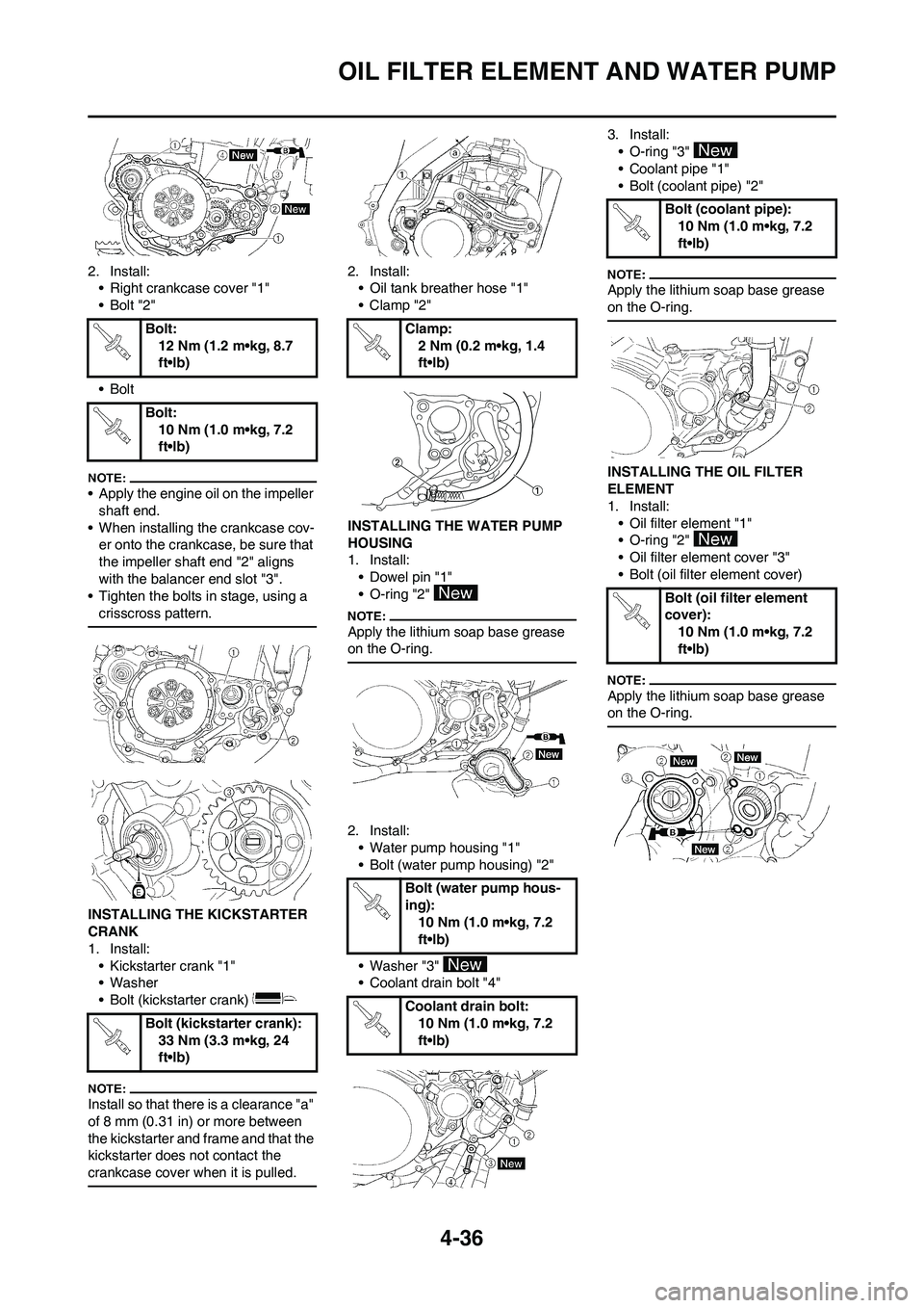
2. Install:
• Right crankcase cover "1"
•Bolt "2"
•Bolt
• Apply the engine oil on the impeller
shaft end.
• When installing the crankcase cov-
er onto the crankcase, be sure that
the impeller shaft end "2" aligns
with the balancer end slot "3".
• Tighten the bolts in stage, using a
crisscross pattern.
INSTALLING THE KICKSTARTER
CRANK
1. Install:
• Kickstarter crank "1"
• Washer
• Bolt (kickstarter crank)
Install so that there is a clearance "a"
of 8 mm (0.31 in) or more between
the kickstarter and frame and that the
kickstarter does not contact the
crankcase cover when it is pulled.
2. Install:
• Oil tank breather hose "1"
•Clamp "2"
INSTALLING THE WATER PUMP
HOUSING
1. Install:
• Dowel pin "1"
• O-ring "2"
Apply the lithium soap base grease
on the O-ring.
2. Install:
• Water pump housing "1"
• Bolt (water pump housing) "2"
• Washer "3"
• Coolant drain bolt "4"3. Install:
• O-ring "3"
• Coolant pipe "1"
• Bolt (coolant pipe) "2"
Apply the lithium soap base grease
on the O-ring.
INSTALLING THE OIL FILTER
ELEMENT
1. Install:
• Oil filter element "1"
• O-ring "2"
• Oil filter element cover "3"
• Bolt (oil filter element cover)
Apply the lithium soap base grease
on the O-ring.
Bolt:
12 Nm (1.2 m•kg, 8.7
ft•lb)
Bolt:
10 Nm (1.0 m•kg, 7.2
ft•lb)
Bolt (kickstarter crank):
33 Nm (3.3 m•kg, 24
ft•lb)Clamp:
2 Nm (0.2 m•kg, 1.4
ft•lb)
Bolt (water pump hous-
ing):
10 Nm (1.0 m•kg, 7.2
ft•lb)
Coolant drain bolt:
10 Nm (1.0 m•kg, 7.2
ft•lb)
Bolt (coolant pipe):
10 Nm (1.0 m•kg, 7.2
ft•lb)
Bolt (oil filter element
cover):
10 Nm (1.0 m•kg, 7.2
ft•lb)
Page 178 of 188

7-1
ENGINE
TUNING
ENGINE
CARBURETOR SETTING
• The air/fuel mixture will vary de-
pending on atmospheric conditions.
Therefore, it is necessary to take
into consideration the air pressure,
ambient temperature, humidity,
etc., when adjusting the carburetor.
• Perform a test run to check for prop-
er engine performance (e.g., throt-
tle response) and spark plug(-s)
discoloration or fouling. Use these
readings to determine the best pos-
sible carburetor setting.
It is recommended to keep a record of
all carburetor settings and external
conditions (e.g., atmospheric condi-
tions, track/surface conditions, lap
times) to make future carburetor set-
ting easier.
• The carburetor is a part of the
fuel line. Therefore, be sure to in-
stall it in a wellventilated area,
away from flammable objects
and any sources of fire.
• Never look into the carburetor in-
take. Flames may shoot out from
the pipe if the engine backfires
while it is being started. Gasoline
may be discharged from the ac-
celerator pump nozzle when the
carburetor has been removed.
• The carburetor is extremely sen-
sitive to foreign matter (dirt,
sand, water, etc.). During instal-
lation, do not allow foreign mat-
ter to get into the carburetor.
• Always handle the carburetor
and its components carefully.
Even slight scratches, bends or
damage to carburetor parts may
prevent the carburetor from
functioning correctly. Carefully
perform all servicing with the ap-
propriate tools and without ap-
plying excessive force.
• When the engine is stopped or
when riding at no load, do not
open and close the throttle un-
necessarily. Otherwise, too
much fuel may be discharged,
starting may become difficult or
the engine may not run well.
• After installing the carburetor,
check that the throttle operates correctly and opens and closes
smoothly.
ATMOSPHERIC CONDITIONS AND
CARBURETOR SETTINGS
The air density (i.e., concentration of
oxygen in the air) determines the rich-
ness or leanness of the air/fuel mix-
ture.
• Higher temperature expands the air
with its resultant reduced density.
• Higher humidity reduces the
amount of oxygen in the air by so
much of the water vapor in the
same air.
• Lower atmospheric pressure (at a
high altitude) reduces the density of
the air.
EFFECT OF SETTING PARTS IN
RELATION TO THROTTLE VALVE
OPENING
A. Closed
B. Fully open
1. Pilot screw/pilot jet
2. Throttle valve cutaway
3. Jet needle
4. Main jetCONSTRUCTION OF
CARBURETOR AND SETTING
PARTS
The FLATCR carburetor has a prima-
ry main jet. This type of main jet is
perfect for racing machines since it
supplies an even flow of fuel, even at
full load. Use the main jet and the jet
needle to set the carburetor.
The FLATCR carburetor is manufac-
tured with a pilot screw. The pilot
screw adjustment ranges from fully
closed throttle to 1/4 open throttle.
1. Jet needle
2. Pilot air jet
3. Needle jet
4. Main jet
5. Pilot jet
6. Pilot screw
ADJUSTING THE MAIN JET
The richness of the air-fuel mixture at
full throttle can be set by changing the
main jet "1".
If the air-fuel mixture is too rich or too
lean, the engine power will drop, re-
sulting in poor acceleration.
Effects of changing the main jet
(reference)
A. Idle
B. Fully open
1. #162
2. #158 Air
tem
p.Hu-
midi-
tyAir
pres-
sure
(alti-
tude)Mix-
tureSet-
ting
High HighLow
(high)Rich-
erLean-
er
Low LowHigh
(low)Lean-
erRich-
er
Standard main jet #160