check engine YAMAHA YZ450F 2010 User Guide
[x] Cancel search | Manufacturer: YAMAHA, Model Year: 2010, Model line: YZ450F, Model: YAMAHA YZ450F 2010Pages: 230, PDF Size: 14.09 MB
Page 63 of 230
3-7
ENGINE
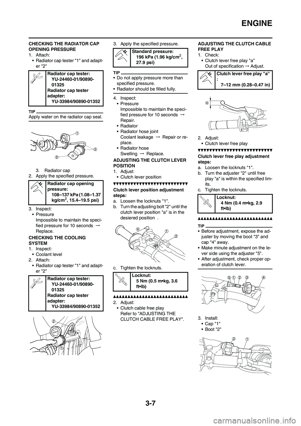
CHECKING THE RADIATOR CAP
OPENING PRESSURE
1. Attach:
• Radiator cap tester "1" and adapt-
er "2"
Apply water on the radiator cap seal.
3. Radiator cap
2. Apply the specified pressure.
3. Inspect:
• Pressure
Impossible to maintain the speci-
fied pressure for 10 seconds →
Replace.
CHECKING THE COOLING
SYSTEM
1. Inspect:
• Coolant level
2. Attach:
• Radiator cap tester "1" and adapt-
er "2"3. Apply the specified pressure.
• Do not apply pressure more than
specified pressure.
• Radiator should be filled fully.
4. Inspect:
•Pressure
Impossible to maintain the speci-
fied pressure for 10 seconds →
Repair.
• Radiator
• Radiator hose joint
Coolant leakage → Repair or re-
place.
• Radiator hose
Swelling → Replace.
ADJUSTING THE CLUTCH LEVER
POSITION
1. Adjust:
• Clutch lever position
Clutch lever position adjustment
steps:
a. Loosen the locknuts "1".
b. Turn the adjusting bolt "2" until the
clutch lever position "a" is in the
desiered position .
c. Tighten the locknuts.
2. Adjust:
• Clutch cable free play
Refer to "ADJUSTING THE
CLUTCH CABLE FREE PLAY".ADJUSTING THE CLUTCH CABLE
FREE PLAY
1. Check:
• Clutch lever free play "a"
Out of specification→Adjust.
2. Adjust:
• Clutch lever free play
Clutch lever free play adjustment
steps:
a. Loosen the locknuts "1".
b. Turn the adjuster "2" until free
play "a" is within the specified lim-
its.
c. Tighten the locknuts.
• Before adjustment, expose the ad-
juster by moving the boot "3" and
cap "4" away.
• Make minute adjustment on the le-
ver side using the adjuster "5".
• After adjustment, check proper op-
eration of clutch lever.
3. Install:
•Cap "1"
• Boot "2" Radiator cap tester:
YU-24460-01/90890-
01325
Radiator cap tester
adapter:
YU-33984/90890-01352
Radiator cap opening
pressure:
108–137 kPa (1.08–1.37
kg/cm
2, 15.4–19.5 psi)
Radiator cap tester:
YU-24460-01/90890-
01325
Radiator cap tester
adapter:
YU-33984/90890-01352
Standard pressure:
196 kPa (1.96 kg/cm2,
27.9 psi)
Locknut:
5 Nm (0.5 m•kg, 3.6
ft•lb)
Clutch lever free play "a"
:
7–12 mm (0.28–0.47 in)
Locknut:
4 Nm (0.4 m•kg, 2.9
ft•lb)
Page 64 of 230
3-8
ENGINE
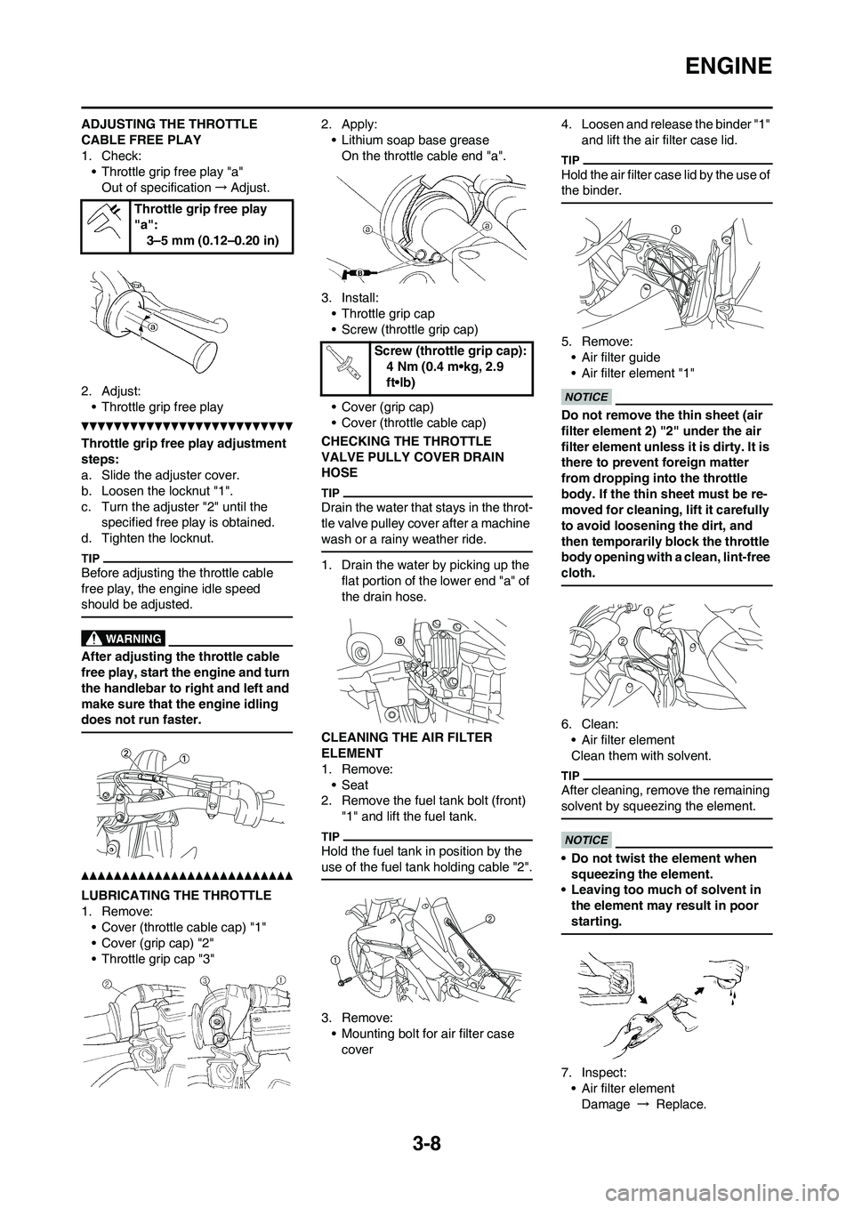
ADJUSTING THE THROTTLE
CABLE FREE PLAY
1. Check:• Throttle grip free play "a"
Out of specification →Adjust.
2. Adjust: • Throttle grip free play
Throttle grip free play adjustment
steps:
a. Slide the adjuster cover.
b. Loosen the locknut "1".
c. Turn the adjuster "2" until the specified free play is obtained.
d. Tighten the locknut.
Before adjusting the throttle cable
free play, the engine idle speed
should be adjusted.
After adjusting th e throttle cable
free play, start the engine and turn
the handlebar to right and left and
make sure that the engine idling
does not run faster.
LUBRICATING THE THROTTLE
1. Remove: • Cover (throttle cable cap) "1"
• Cover (grip cap) "2"
• Throttle grip cap "3" 2. Apply:
• Lithium soap base greaseOn the throttle cable end "a".
3. Install: • Throttle grip cap
• Screw (throttle grip cap)
• Cover (grip cap)
• Cover (throttle cable cap)
CHECKING THE THROTTLE
VALVE PULLY COVER DRAIN
HOSE
Drain the water that stays in the throt-
tle valve pulley cove r after a machine
wash or a rainy weather ride.
1. Drain the water by picking up the flat portion of the lower end "a" of
the drain hose.
CLEANING THE AIR FILTER
ELEMENT
1. Remove: •Seat
2. Remove the fuel tank bolt (front) "1" and lift the fuel tank.
Hold the fuel tank in position by the
use of the fuel tank holding cable "2".
3. Remove:• Mounting bolt for air filter case
cover 4. Loosen and release the binder "1"
and lift the air filter case lid.
Hold the air filter case lid by the use of
the binder.
5. Remove:• Air filter guide
• Air filter element "1"
Do not remove the thin sheet (air
filter element 2) "2" under the air
filter element unless it is dirty. It is
there to prevent foreign matter
from dropping in to the throttle
body. If the thin sheet must be re-
moved for cleaning, lift it carefully
to avoid loosening the dirt, and
then temporarily block the throttle
body opening with a clean, lint-free
cloth.
6. Clean: • Air filter element
Clean them with solvent.
After cleaning, remo ve the remaining
solvent by squeezing the element.
• Do not twist the element when squeezing the element.
• Leaving too much of solvent in
the element may result in poor
starting.
7. Inspect:• Air filter elementDamage → Replace.
Throttle grip free play
"a":
3–5 mm (0.12–0.20 in)
Screw (throttle grip cap): 4 Nm (0.4 m•kg, 2.9
ft•lb)
Page 65 of 230
3-9
ENGINE
8. Apply:• Foam-air-filter oil or equivalent oil to the element
Squeeze out the excess oil. Element
should be wet but not dripping.
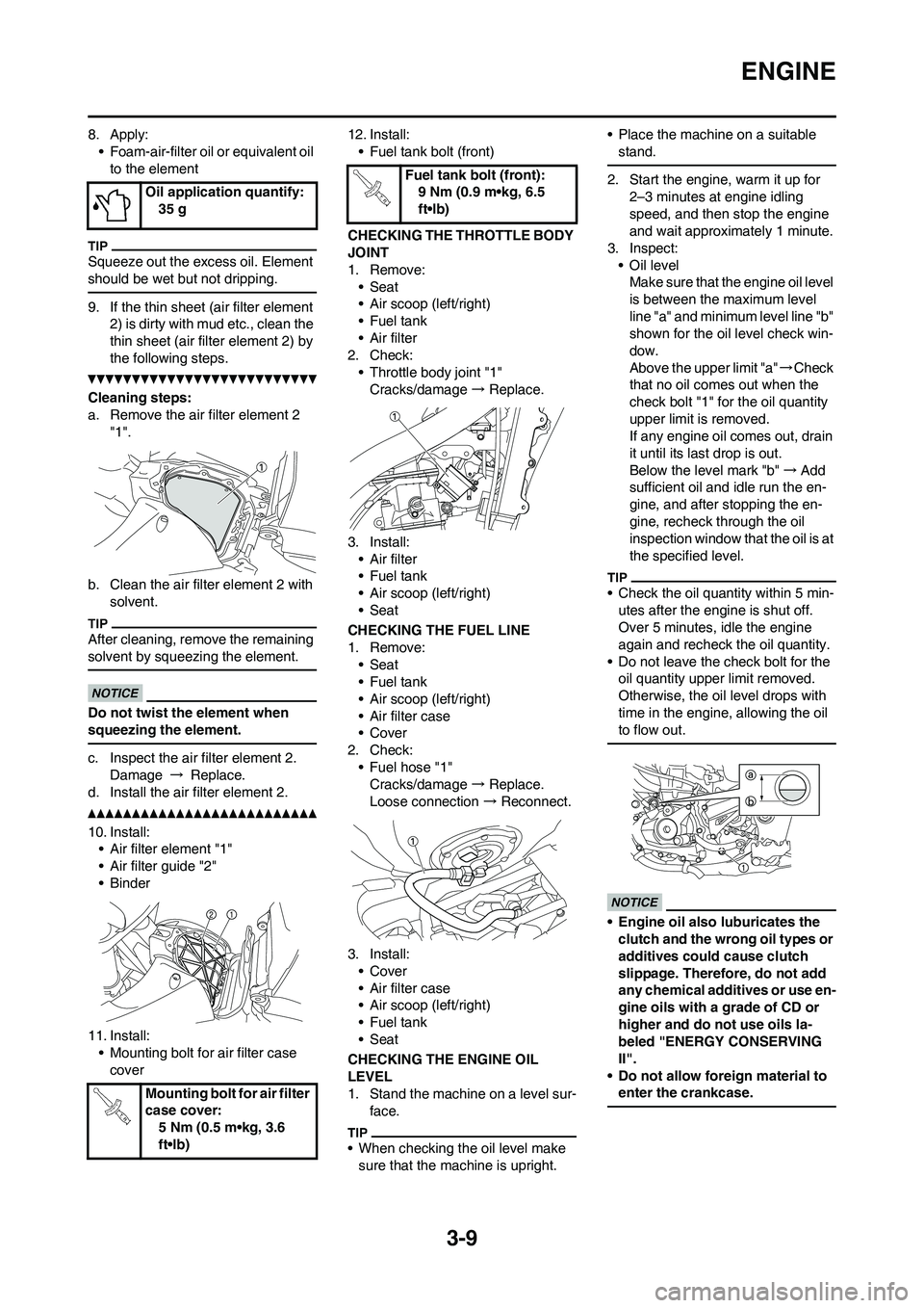
9. If the thin sheet (air filter element 2) is dirty with mud etc., clean the
thin sheet (air filt er element 2) by
the following steps.
Cleaning steps:
a. Remove the air filter element 2 "1".
b. Clean the air filter element 2 with solvent.
After cleaning, remo ve the remaining
solvent by squeezing the element.
Do not twist the element when
squeezing the element.
c. Inspect the air filter element 2. Damage → Replace.
d. Install the air filter element 2.
10. Install: • Air filter element "1"
• Air filter guide "2"
•Binder
11. Install: • Mounting bolt for air filter case
cover 12. Install:
• Fuel tank bolt (front)
CHECKING THE THROTTLE BODY
JOINT
1. Remove: •Seat
• Air scoop (left/right)
•Fuel tank
• Air filter
2. Check: • Throttle body joint "1"
Cracks/damage → Replace.
3. Install: • Air filter
•Fuel tank
• Air scoop (left/right)
•Seat
CHECKING THE FUEL LINE
1. Remove: •Seat
•Fuel tank
• Air scoop (left/right)
• Air filter case
• Cover
2. Check:
• Fuel hose "1"Cracks/damage → Replace.
Loose connection → Reconnect.
3. Install: • Cover
• Air filter case
• Air scoop (left/right)
•Fuel tank
•Seat
CHECKING THE ENGINE OIL
LEVEL
1. Stand the machine on a level sur- face.
• When checking the oil level make sure that the machine is upright. • Place the machine on a suitable
stand.
2. Start the engine, warm it up for 2–3 minutes at engine idling
speed, and then stop the engine
and wait approximately 1 minute.
3. Inspect: • Oil levelMake sure that the engine oil level
is between the maximum level
line "a" and minimum level line "b"
shown for the oil level check win-
dow.
Above the upper limit "a" →Check
that no oil comes out when the
check bolt "1" for the oil quantity
upper limit is removed.
If any engine oil comes out, drain
it until its last drop is out.
Below the level mark "b" →Add
sufficient oil and idle run the en-
gine, and after stopping the en-
gine, recheck through the oil
inspection window that the oil is at
the specified level.
• Check the oil quantity within 5 min- utes after the engin e is shut off.
Over 5 minutes, idle the engine
again and recheck the oil quantity.
• Do not leave the check bolt for the oil quantity upper limit removed.
Otherwise, the oil level drops with
time in the engine, allowing the oil
to flow out.
• Engine oil also luburicates the clutch and the wrong oil types or
additives could cause clutch
slippage. Therefore, do not add
any chemical additives or use en-
gine oils with a grade of CD or
higher and do not use oils la-
beled "ENERGY CONSERVING
II".
• Do not allow fore ign material to
enter the crankcase.
Oil application quantify: 35 g
Mounting bolt for air filter
case cover: 5 Nm (0.5 m•kg, 3.6
ft•lb)
Fuel tank bolt (front):9 Nm (0.9 m•kg, 6.5
ft•lb)
Page 66 of 230
3-10
ENGINE
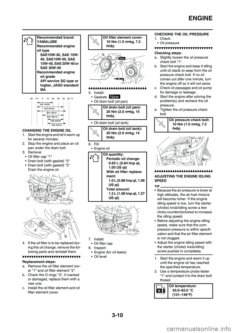
CHANGING THE ENGINE OIL
1. Start the engine and let it warm up for several minutes.
2. Stop the engine and place an oil pan under the drain bolt.
3. Remove: • Oil filler cap "1"
• Drain bolt (with gasket) "2"
• Drain bolt (with gasket) "3"Drain the engine oil.
4. If the oil filter is to be replaced dur- ing this oil change, remove the fol-
lowing parts and reinstall them.
Replacement steps:
a. Remove the oil filter element cov-er "1" and oil filter element "2".
b. Check the O-rings "3", if cracked or damaged, replace them with a
new one.
c. Install the oil filter element and oil filter element cover.
5. Install:• Gaskets
• Oil drain bolt (oil pan)
• Oil drain bolt (oil tank)
6. Fill: • Engine oil
7. Install: • Oil filler cap
8. Inspect:
• Engine (for oil leaks)
• Oil level CHECKING THE OIL PRESSURE
1. Check:
• Oil pressure
Checking steps:
a. Slightly loosen the oil pressure check bolt "1".
b. Start the engine and keep it idling until oil starts to seep from the oil
pressure check bolt. If no oil
comes out after one minute, turn
the engine off so it will not seize.
c. Check oil passages and oil pump
for damage or leakage.
d. Start the engine after solving the problem(s) and recheck the oil
pressure.
e. Tighten the oil pressure check bolt.
ADJUSTING THE ENGINE IDLING
SPEED
• Because the air pressure is lower at
high altitudes, the air-fuel mixture
will become richer. If the engine
idling speed is low, turn the starter
(choke) knob/idling screw a few
clicks counterclockwise to increase
the idling speed.
• Before adjusting the engine idling speed, make sure that the com-
pression pressure is within specifi-
cation and that the air filter element
is not clogged.
• Adjust the engine idling speed with
the starter (choke) knob/idling
screw pushed in completely.
1. Start the engine and warm it up until the engine oil has reached
the specified temperature.
2. Use a temperature probe tester "1" and contact it to the drain bolt
thread.
Recommended brand:
YAMALUBE
Recommended engine
oil type
SAE10W-30, SAE 10W-
40, SAE10W-50, SAE
15W-40, SAE 20W-40 or
SAE 20W-50
Recommended engine
oil grade
API service SG type or
higher, JASO standard
MA
Oil filter element cover:10 Nm (1.0 m•kg, 7.2
ft•lb)
Oil drain bolt (oil pan): 20 Nm (2.0 m•kg, 14
ft•lb)
Oil drain bolt (oil tank): 20 Nm (2.0 m•kg, 14
ft•lb)
Oil quantity: Periodic oil change:0.95 L (0.84 Imp qt,
1.00 US qt)
With oil filter replace-
ment: 1.0 L (0.88 Imp qt, 1.06
US qt)
Total amount: 1.2 L (1.06 Imp qt, 1.27
US qt)
Oil pressure check bolt:
10 Nm (1.0 m•kg, 7.2
ft•lb)
Oil temperature: 55.0–65.0 °C
(131–149°F)
Page 67 of 230
3-11
ENGINE
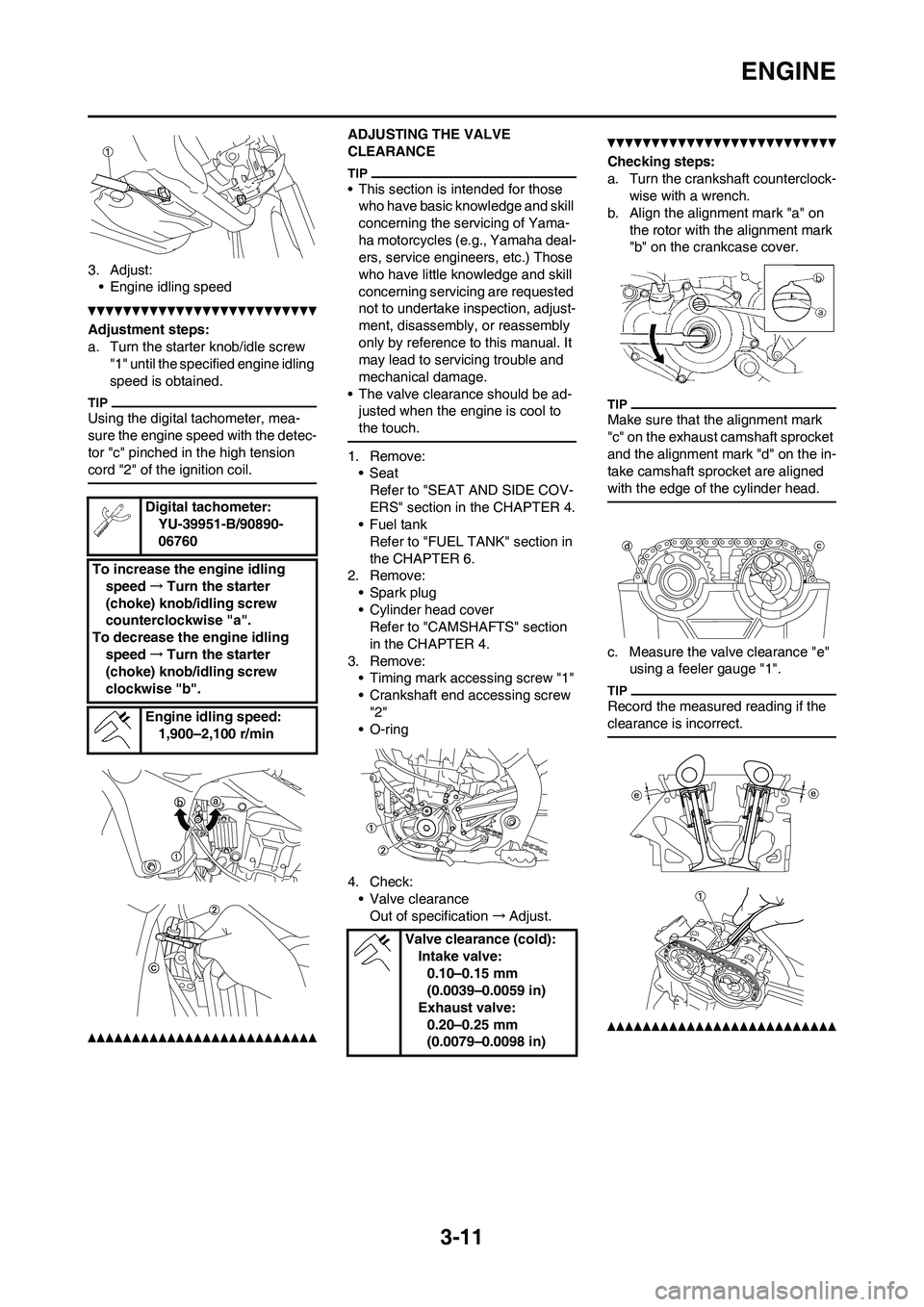
3. Adjust:• Engine idling speed
Adjustment steps:
a. Turn the starter knob/idle screw "1" until the specified engine idling
speed is obtained.
Using the digital tachometer, mea-
sure the engine speed with the detec-
tor "c" pinched in the high tension
cord "2" of the ignition coil.
ADJUSTING THE VALVE
CLEARANCE
• This section is intended for those who have basic knowledge and skill
concerning the servicing of Yama-
ha motorcycles (e.g., Yamaha deal-
ers, service engineers, etc.) Those
who have little knowledge and skill
concerning servicing are requested
not to undertake in spection, adjust-
ment, disassembly, or reassembly
only by reference to this manual. It
may lead to servicing trouble and
mechanical damage.
• The valve clearance should be ad- justed when the engine is cool to
the touch.
1. Remove:•Seat
Refer to "SEAT AND SIDE COV-
ERS" section in the CHAPTER 4.
•Fuel tank
Refer to "FUEL TANK" section in
the CHAPTER 6.
2. Remove:
• Spark plug
• Cylinder head coverRefer to "CAMSHAFTS" section
in the CHAPTER 4.
3. Remove: • Timing mark accessing screw "1"
• Crankshaft end accessing screw "2"
• O-ring
4. Check: • Valve clearanceOut of specification →Adjust.
Checking steps:
a. Turn the crankshaft counterclock-
wise with a wrench.
b. Align the alignment mark "a" on the rotor with the alignment mark
"b" on the crankcase cover.
Make sure that the alignment mark
"c" on the exhaust camshaft sprocket
and the alignment mark "d" on the in-
take camshaft sprocket are aligned
with the edge of the cylinder head.
c. Measure the valve clearance "e" using a feeler gauge "1".
Record the measured reading if the
clearance is incorrect.
Digital tachometer:
YU-39951-B/90890-
06760
To increase the engine idling speed →Turn the starter
(choke) knob/idling screw
counterclockwise "a".
To decrease the engine idling
speed →Turn the starter
(choke) knob/idling screw
clockwise "b".
Engine idling speed:1,900–2,100 r/min
Valve clearance (cold):Intake valve:0.10–0.15 mm
(0.0039–0.0059 in)
Exhaust valve: 0.20–0.25 mm
(0.0079–0.0098 in)
Page 74 of 230
3-18
CHASSIS
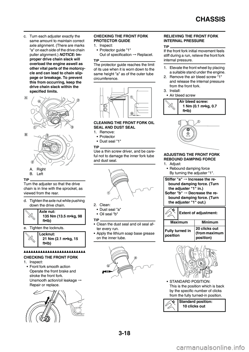
c. Turn each adjuster exactly the
same amount to maintain correct
axle alignment. (There are marks
"a" on each side of the drive chain
puller alignment.) NOTICE: Im-
proper drive chain slack will
overload the engine aswell as
other vital parts of the motorcy-
cle and can lead to chain slip-
page or breakage. To prevent
this from occurring, keep the
drive chain slack within the
specified limits.
A. Right
B. Left
Turn the adjuster so that the drive
chain is in line with the sprocket, as
viewed from the rear.
d. Tighten the axle nut while pushing
down the drive chain.
e. Tighten the locknuts.
CHECKING THE FRONT FORK
1. Inspect:
• Front fork smooth action
Operate the front brake and
stroke the front fork.
Unsmooth action/oil leakage→
Repair or replace.CHECKING THE FRONT FORK
PROTECTOR GUIDE
1. Inspect:
• Protector guide "1"
Out of specification→Replacet.
The protector guide reaches the limit
of its use when it is worn down to the
same height "a" as of the outer tube
circumference.
CLEANING THE FRONT FORK OIL
SEAL AND DUST SEAL
1. Remove:
•Protector
• Dust seal "1"
Use a thin screw driver, and be care-
ful not to damage the inner fork tube
and dust seal.
2. Clean:
• Dust seal "a"
• Oil seal "b"
• Clean the dust seal and oil seal af-
ter every run.
• Apply the lithium soap base grease
on the inner tube.
RELIEVING THE FRONT FORK
INTERNAL PRESSURE
If the front fork initial movement feels
stiff during a run, relieve the front fork
internal pressure.
1. Elevate the front wheel by placing
a suitable stand under the engine.
2. Remove the air bleed screw "1"
and release the internal pressure
from the front fork.
3. Install:
• Air bleed screw
ADJUSTING THE FRONT FORK
REBOUND DAMPING FORCE
1. Adjust:
• Rebound damping force
By turning the adjuster "1".
• STANDARD POSITION:
This is the position which is back
by the specific number of clicks
from the fully turned-in position. Axle nut:
135 Nm (13.5 m•kg, 98
ft•lb)
Locknut:
21 Nm (2.1 m•kg, 15
ft•lb)
Air bleed screw:
1 Nm (0.1 m•kg, 0.7
ft•lb)
Stiffer "a" →Increase the re-
bound damping force. (Turn
the adjuster "1" in.)
Softer "b" →Decrease the re-
bound damping force. (Turn
the adjuster "1" out.)
Extent of adjustment:
Maximum Minimum
Fully turned in
position20 clicks out
(from maximum
position)
Standard position:
10 clicks out
Page 77 of 230
3-21
CHASSIS
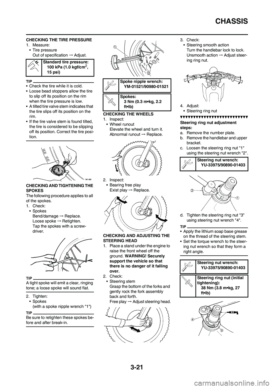
CHECKING THE TIRE PRESSURE
1. Measure:
• Tire pressure
Out of specification→Adjust.
• Check the tire while it is cold.
• Loose bead stoppers allow the tire
to slip off its position on the rim
when the tire pressure is low.
• A tilted tire valve stem indicates that
the tire slips off its position on the
rim.
• If the tire valve stem is found tilted,
the tire is considered to be slipping
off its position. Correct the tire posi-
tion.
CHECKING AND TIGHTENING THE
SPOKES
The following procedure applies to all
of the spokes.
1. Check:
• Spokes
Bend/damage→Replace.
Loose spoke→Retighten.
Tap the spokes with a screw-
driver.
A tight spoke will emit a clear, ringing
tone; a loose spoke will sound flat.
2. Tighten:
• Spokes
(with a spoke nipple wrench "1")
Be sure to retighten these spokes be-
fore and after break-in.
CHECKING THE WHEELS
1. Inspect:
• Wheel runout
Elevate the wheel and turn it.
Abnormal runout→ Replace.
2. Inspect:
• Bearing free play
Exist play→Replace.
CHECKING AND ADJUSTING THE
STEERING HEAD
1. Place a stand under the engine to
raise the front wheel off the
ground. WARNING! Securely
support the vehicle so that
there is no danger of it falling
over.
2. Check:
• Steering stem
Grasp the bottom of the forks and
gently rock the fork assembly
back and forth.
Free play→Adjust steering head.3. Check:
• Steering smooth action
Turn the handlebar lock to lock.
Unsmooth action→Adjust steer-
ing ring nut.
4. Adjust:
• Steering ring nut
Steering ring nut adjustment
steps:
a. Remove the number plate.
b. Remove the handlebar and upper
bracket.
c. Loosen the steering ring nut "1"
using the steering nut wrench "2".
d. Tighten the steering ring nut "3"
using steering nut wrench "4".
• Apply the lithium soap base grease
on the thread of the steering stem.
• Set the torque wrench to the steer-
ing nut wrench so that they form a
right angle.
Standard tire pressure:
100 kPa (1.0 kgf/cm2,
15 psi)
Spoke nipple wrench:
YM-01521/90980-01521
Spokes:
3 Nm (0.3 m•kg, 2.2
ft•lb)
Steering nut wrench:
YU-33975/90890-01403
Steering nut wrench:
YU-33975/90890-01403
Steering ring nut (initial
tightening):
38 Nm (3.8 m•kg, 27
ft•lb)
Page 80 of 230
3-24
ELECTRICAL
ELECTRICAL
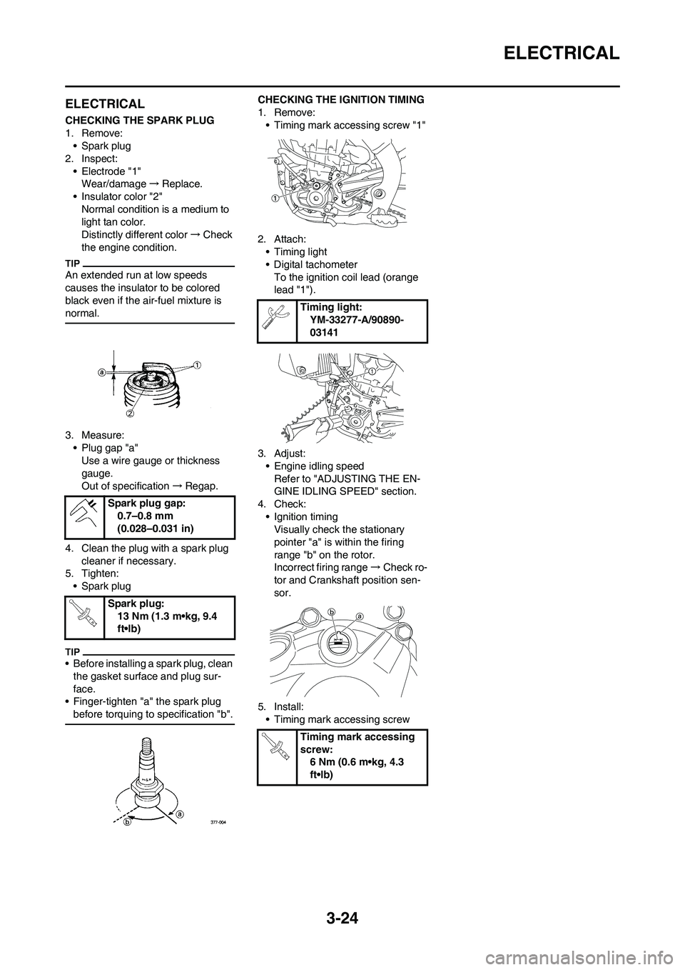
CHECKING THE SPARK PLUG
1. Remove:
• Spark plug
2. Inspect:
• Electrode "1"
Wear/damage→Replace.
• Insulator color "2"
Normal condition is a medium to
light tan color.
Distinctly different color→Check
the engine condition.
An extended run at low speeds
causes the insulator to be colored
black even if the air-fuel mixture is
normal.
3. Measure:
• Plug gap "a"
Use a wire gauge or thickness
gauge.
Out of specification→Regap.
4. Clean the plug with a spark plug
cleaner if necessary.
5. Tighten:
• Spark plug
• Before installing a spark plug, clean
the gasket surface and plug sur-
face.
• Finger-tighten "a" the spark plug
before torquing to specification "b".
CHECKING THE IGNITION TIMING
1. Remove:
• Timing mark accessing screw "1"
2. Attach:
• Timing light
• Digital tachometer
To the ignition coil lead (orange
lead "1").
3. Adjust:
• Engine idling speed
Refer to "ADJUSTING THE EN-
GINE IDLING SPEED" section.
4. Check:
• Ignition timing
Visually check the stationary
pointer "a" is within the firing
range "b" on the rotor.
Incorrect firing range→Check ro-
tor and Crankshaft position sen-
sor.
5. Install:
• Timing mark accessing screw Spark plug gap:
0.7–0.8 mm
(0.028–0.031 in)
Spark plug:
13 Nm (1.3 m•kg, 9.4
ft•lb)
Timing light:
YM-33277-A/90890-
03141
Timing mark accessing
screw:
6 Nm (0.6 m•kg, 4.3
ft•lb)
Page 81 of 230
3-25
ELECTRICAL
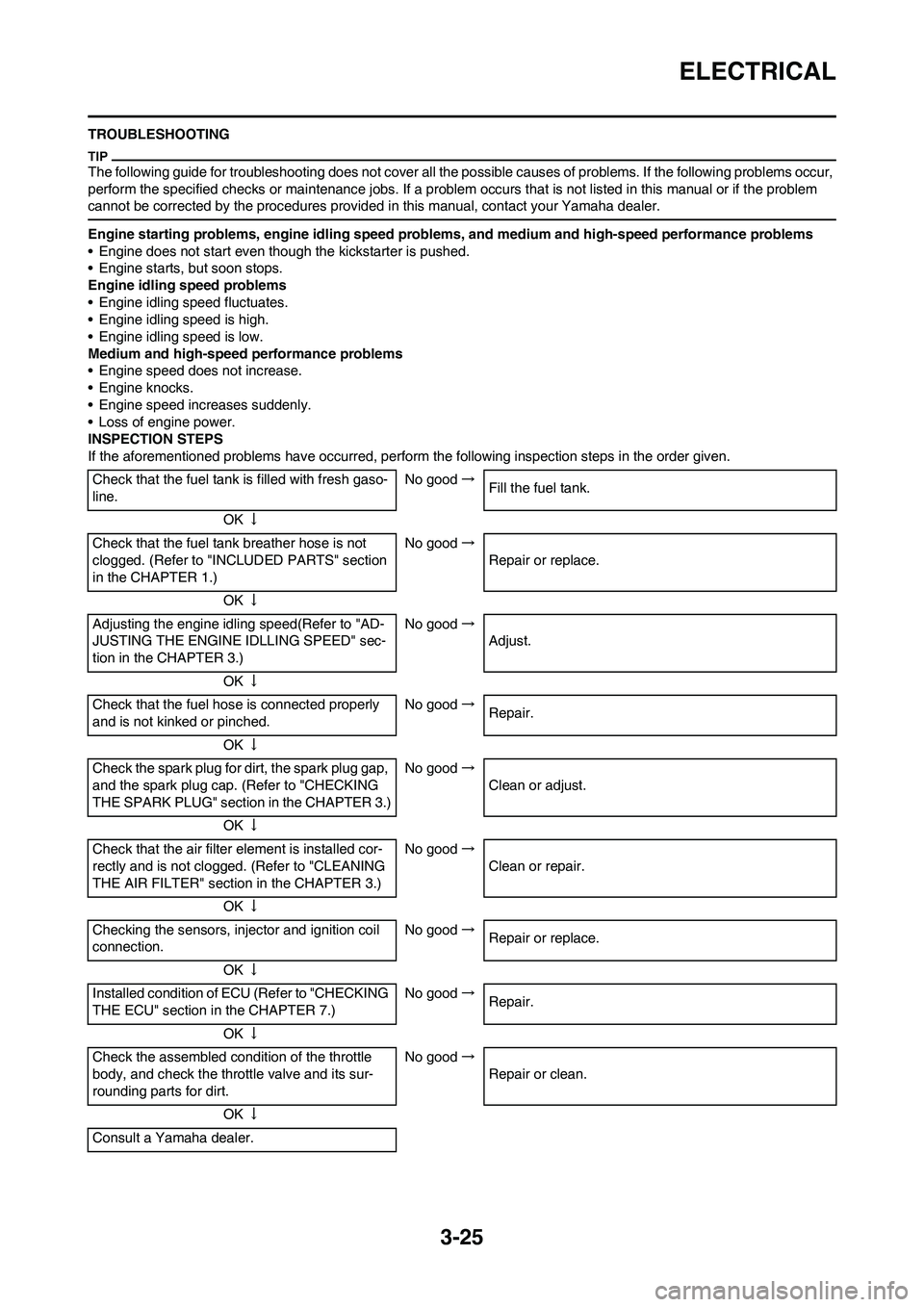
TROUBLESHOOTING
The following guide for troubleshooting does not cover all the possible causes of problems. If the following problems occur,
perform the specified checks or maintenance jobs. If a problem occurs that is not listed in this manual or if the problem
cannot be corrected by the procedures provided in this manual, contact your Yamaha dealer.
Engine starting problems, engine idling speed problems, and medium and high-speed performance problems
• Engine does not start even though the kickstarter is pushed.
• Engine starts, but soon stops.
Engine idling speed problems
• Engine idling speed fluctuates.
• Engine idling speed is high.
• Engine idling speed is low.
Medium and high-speed performance problems
• Engine speed does not increase.
• Engine knocks.
• Engine speed increases suddenly.
• Loss of engine power.
INSPECTION STEPS
If the aforementioned problems have occurred, perform the following inspection steps in the order given.
Check that the fuel tank is filled with fresh gaso-
line.No good→
Fill the fuel tank.
OK↓
Check that the fuel tank breather hose is not
clogged. (Refer to "INCLUDED PARTS" section
in the CHAPTER 1.)No good→
Repair or replace.
OK↓
Adjusting the engine idling speed(Refer to "AD-
JUSTING THE ENGINE IDLLING SPEED" sec-
tion in the CHAPTER 3.)No good→
Adjust.
OK↓
Check that the fuel hose is connected properly
and is not kinked or pinched.No good→
Repair.
OK↓
Check the spark plug for dirt, the spark plug gap,
and the spark plug cap. (Refer to "CHECKING
THE SPARK PLUG" section in the CHAPTER 3.)No good→
Clean or adjust.
OK↓
Check that the air filter element is installed cor-
rectly and is not clogged. (Refer to "CLEANING
THE AIR FILTER" section in the CHAPTER 3.)No good→
Clean or repair.
OK↓
Checking the sensors, injector and ignition coil
connection.No good→
Repair or replace.
OK↓
Installed condition of ECU (Refer to "CHECKING
THE ECU" section in the CHAPTER 7.)No good→
Repair.
OK↓
Check the assembled condition of the throttle
body, and check the throttle valve and its sur-
rounding parts for dirt.No good→
Repair or clean.
OK↓
Consult a Yamaha dealer.
Page 90 of 230
4-9
RADIATOR
HANDLING NOTE
Do not remove the radiator cap
when the engine and radiator are
hot. Scalding hot fluid and steam
may be blown out under pressure,
which could cause serious injury.
When the engine has cooled, open
the radiator cap by the following
procedure:
Place a thick rag, like a towel, over
the radiator cap, slowly rotate the
cap counterclockwise to the de-
tent. This procedure allows any re-
sidual pressure to escape. When
the hissing sound has stopped,
press down on the cap while turn-
ing counterclockwise and remove
it.
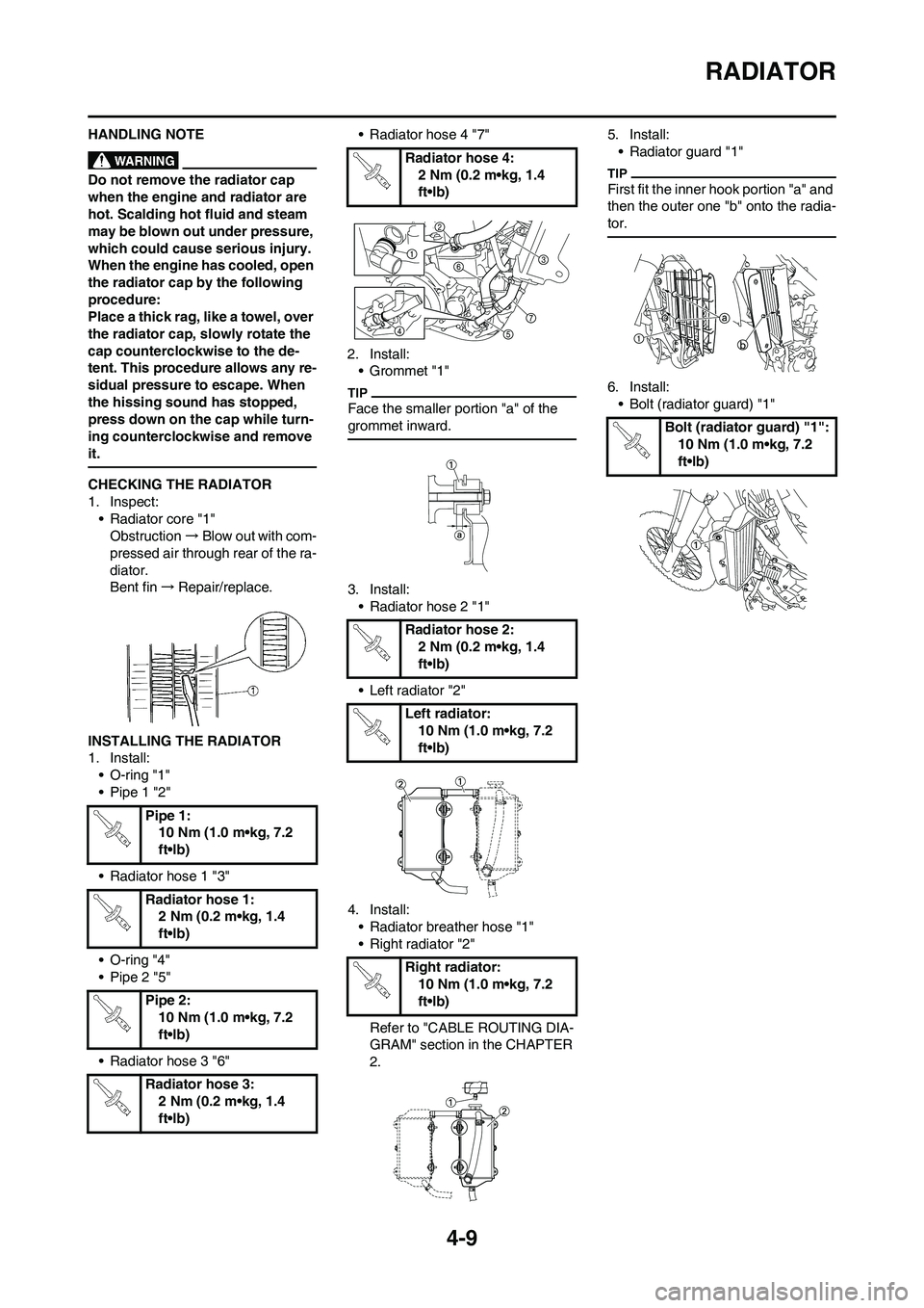
CHECKING THE RADIATOR
1. Inspect:
• Radiator core "1"
Obstruction→Blow out with com-
pressed air through rear of the ra-
diator.
Bent fin→Repair/replace.
INSTALLING THE RADIATOR
1. Install:
• O-ring "1"
• Pipe 1 "2"
• Radiator hose 1 "3"
• O-ring "4"
• Pipe 2 "5"
• Radiator hose 3 "6"• Radiator hose 4 "7"
2. Install:
• Grommet "1"
Face the smaller portion "a" of the
grommet inward.
3. Install:
• Radiator hose 2 "1"
• Left radiator "2"
4. Install:
• Radiator breather hose "1"
• Right radiator "2"
Refer to "CABLE ROUTING DIA-
GRAM" section in the CHAPTER
2.5. Install:
• Radiator guard "1"
First fit the inner hook portion "a" and
then the outer one "b" onto the radia-
tor.
6. Install:
• Bolt (radiator guard) "1"
Pipe 1:
10 Nm (1.0 m•kg, 7.2
ft•lb)
Radiator hose 1:
2 Nm (0.2 m•kg, 1.4
ft•lb)
Pipe 2:
10 Nm (1.0 m•kg, 7.2
ft•lb)
Radiator hose 3:
2 Nm (0.2 m•kg, 1.4
ft•lb)
Radiator hose 4:
2 Nm (0.2 m•kg, 1.4
ft•lb)
Radiator hose 2:
2 Nm (0.2 m•kg, 1.4
ft•lb)
Left radiator:
10 Nm (1.0 m•kg, 7.2
ft•lb)
Right radiator:
10 Nm (1.0 m•kg, 7.2
ft•lb)
Bolt (radiator guard) "1":
10 Nm (1.0 m•kg, 7.2
ft•lb)