engine YAMAHA YZ450F 2010 Repair Manual
[x] Cancel search | Manufacturer: YAMAHA, Model Year: 2010, Model line: YZ450F, Model: YAMAHA YZ450F 2010Pages: 230, PDF Size: 14.09 MB
Page 139 of 230

4-58
TRANSMISSION, SHIFT CAM AND SHIFT FORK
TRANSMISSION, SHIFT CAM AND SHIFT FORK
REMOVING THE TRANSMISSION, SHIFT CAM AND SHIFT FORK
Order Part name Q'ty Remarks
Engine Refer to "ENGINE REMOVAL" section.
Separate the crankcase.Refer to "CRANKCASE AND CRANK-
SHAFT" section.
1 Main axle 1 Refer to removal section.
2 Drive axle 1 Refer to removal section.
3 Shift cam 1 Refer to removal section.
4 Shift fork 3 1 Refer to removal section.
5 Shift fork 2 1 Refer to removal section.
6 Shift fork 1 1 Refer to removal section.
7 Collar 1
Page 141 of 230
4-60
TRANSMISSION, SHIFT CAM AND SHIFT FORK
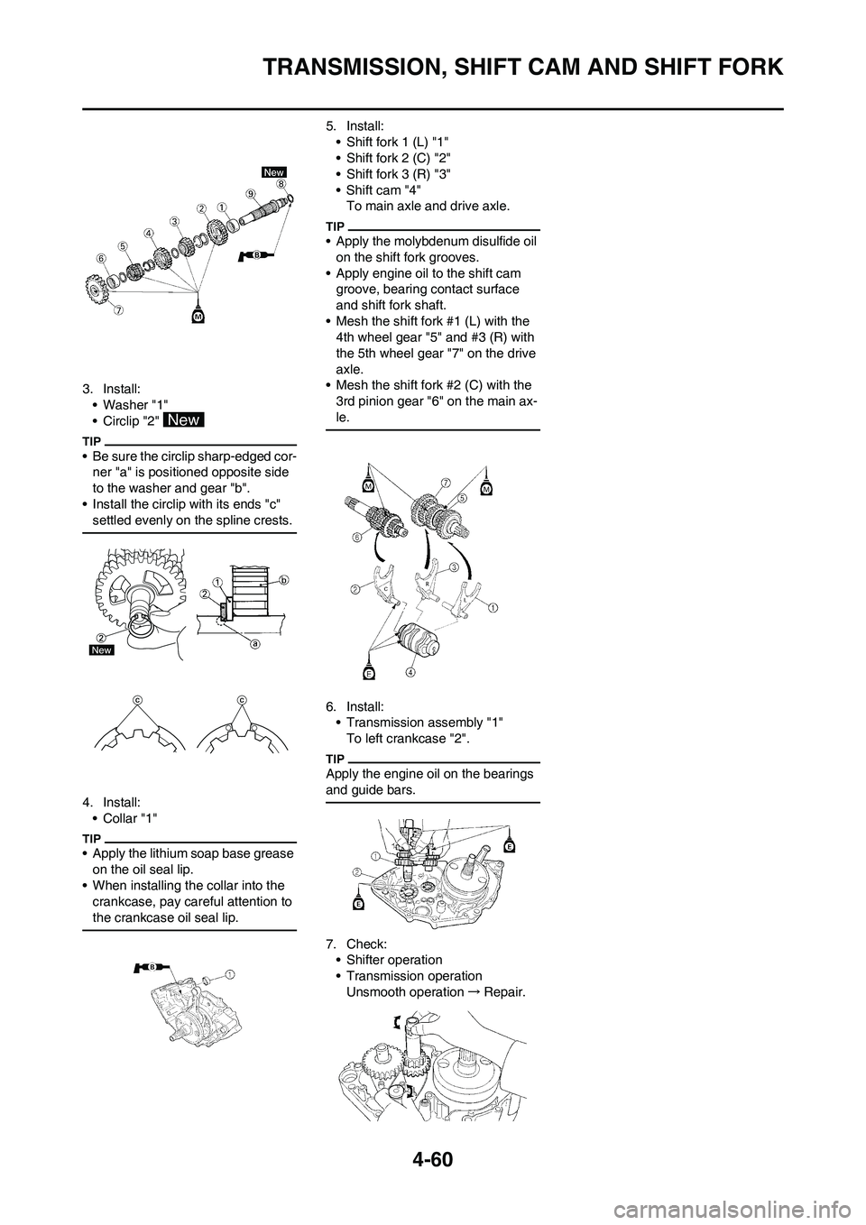
3. Install:
• Washer "1"
• Circlip "2"
• Be sure the circlip sharp-edged cor-
ner "a" is positioned opposite side
to the washer and gear "b".
• Install the circlip with its ends "c"
settled evenly on the spline crests.
4. Install:
•Collar "1"
• Apply the lithium soap base grease
on the oil seal lip.
• When installing the collar into the
crankcase, pay careful attention to
the crankcase oil seal lip.
5. Install:
• Shift fork 1 (L) "1"
• Shift fork 2 (C) "2"
• Shift fork 3 (R) "3"
• Shift cam "4"
To main axle and drive axle.
• Apply the molybdenum disulfide oil
on the shift fork grooves.
• Apply engine oil to the shift cam
groove, bearing contact surface
and shift fork shaft.
• Mesh the shift fork #1 (L) with the
4th wheel gear "5" and #3 (R) with
the 5th wheel gear "7" on the drive
axle.
• Mesh the shift fork #2 (C) with the
3rd pinion gear "6" on the main ax-
le.
6. Install:
• Transmission assembly "1"
To left crankcase "2".
Apply the engine oil on the bearings
and guide bars.
7. Check:
• Shifter operation
• Transmission operation
Unsmooth operation→Repair.
Page 142 of 230
5-1
FRONT WHEEL AND REAR WHEEL
CHASSIS
This section is intended for those who have basic knowledge and skill concerning the servicing of Yamaha motorcycles
(e.g., Yamaha dealers, service engineers, etc.) Those who have little knowledge and skill concerning servicing are request-
ed not to undertake inspection, adjustment, disassembly, or reassembly only by reference to this manual. It may lead to
servicing trouble and mechanical damage.
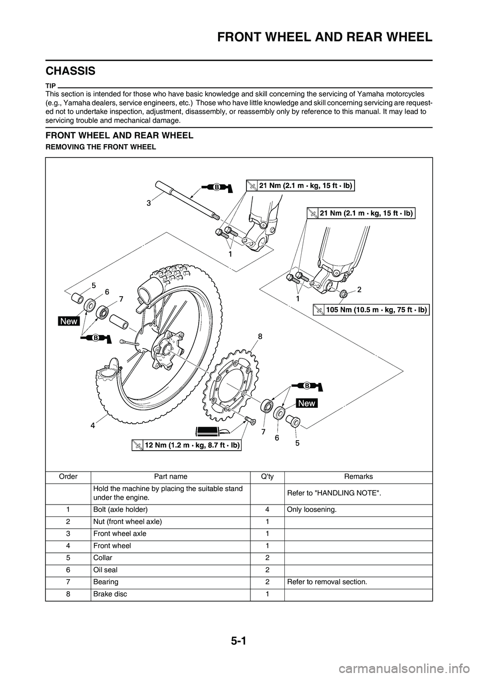
FRONT WHEEL AND REAR WHEEL
REMOVING THE FRONT WHEEL
Order Part name Q'ty Remarks Hold the machine by placing the suitable stand
under the engine. Refer to "HANDLING NOTE".
1 Bolt (axle holder) 4 Only loosening.
2 Nut (front wheel axle) 1
3 Front wheel axle 1
4 Front wheel 1
5 Collar 2
6 Oil seal 2
7 Bearing 2 Refer to removal section.
8 Brake disc 1
Page 143 of 230
5-2
FRONT WHEEL AND REAR WHEEL
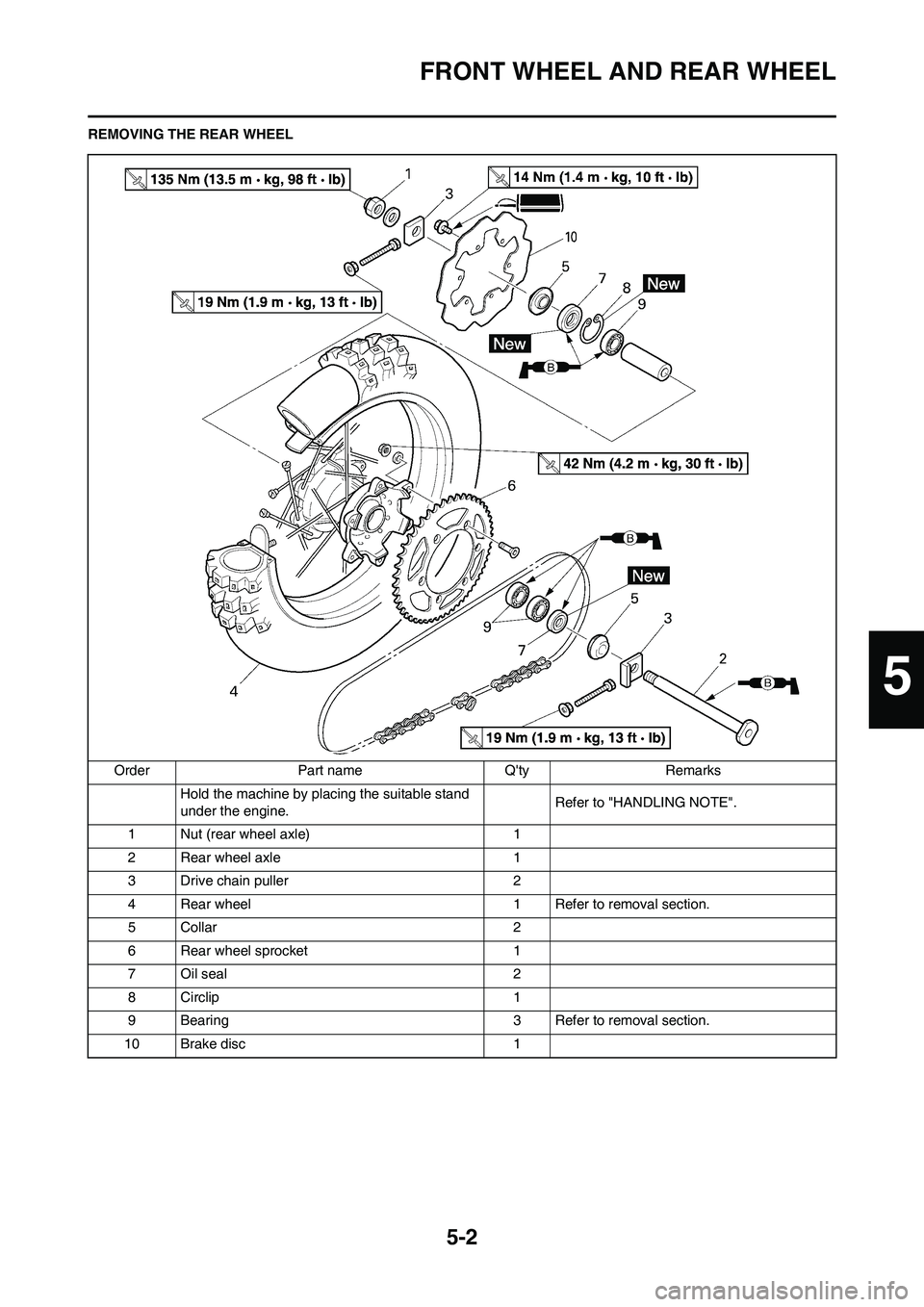
REMOVING THE REAR WHEEL
Order Part name Q'ty Remarks
Hold the machine by placing the suitable stand
under the engine.Refer to "HANDLING NOTE".
1 Nut (rear wheel axle) 1
2 Rear wheel axle 1
3 Drive chain puller 2
4 Rear wheel 1 Refer to removal section.
5 Collar 2
6 Rear wheel sprocket 1
7 Oil seal 2
8 Circlip 1
9 Bearing 3 Refer to removal section.
10 Brake disc 1
5
Page 147 of 230
5-6
FRONT BRAKE AND REAR BRAKE
FRONT BRAKE AND REAR BRAKE
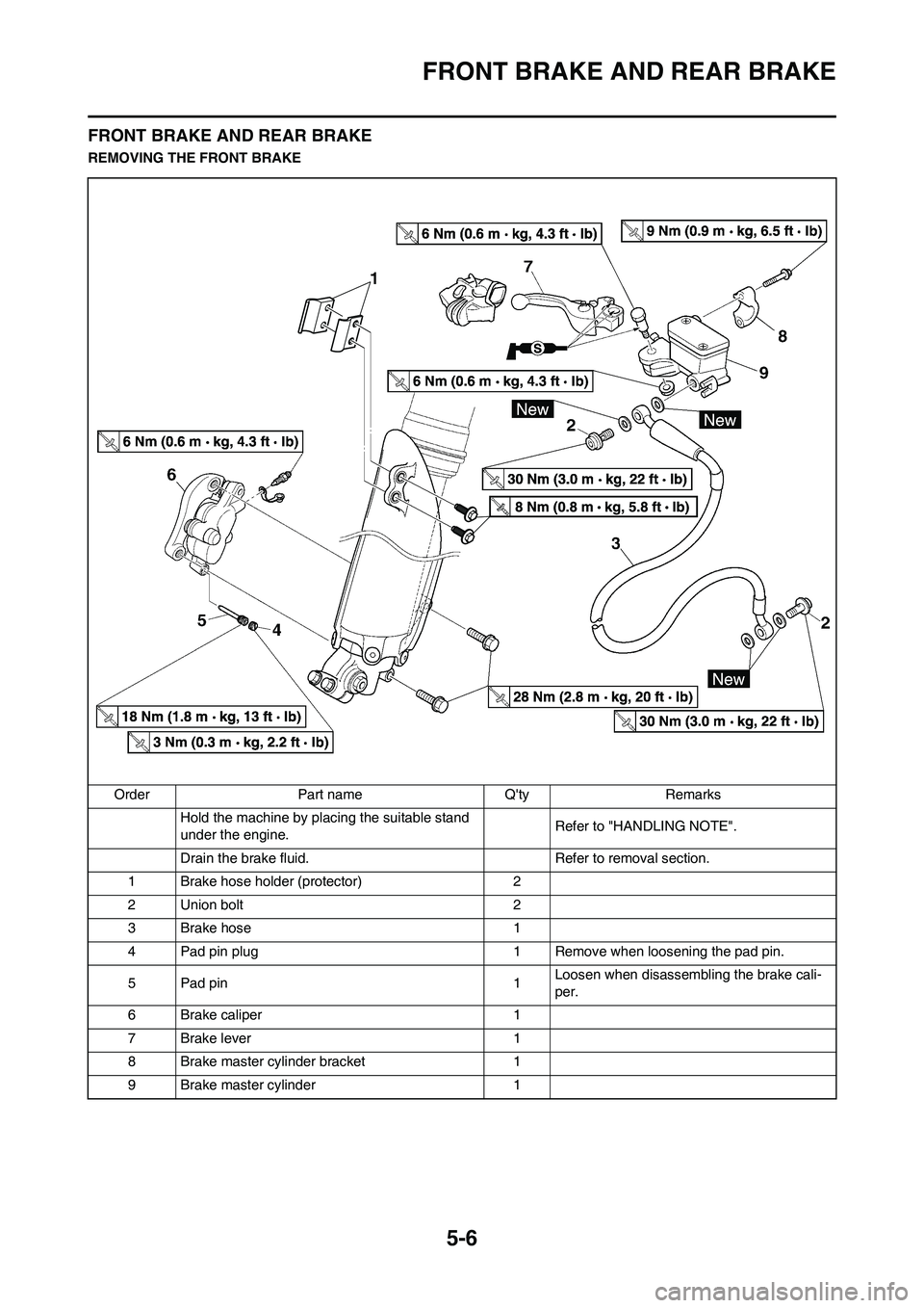
REMOVING THE FRONT BRAKE
Order Part name Q'ty Remarks
Hold the machine by placing the suitable stand
under the engine.Refer to "HANDLING NOTE".
Drain the brake fluid. Refer to removal section.
1 Brake hose holder (protector) 2
2 Union bolt 2
3 Brake hose 1
4 Pad pin plug 1 Remove when loosening the pad pin.
5Pad pin 1Loosen when disassembling the brake cali-
per.
6 Brake caliper 1
7Brake lever 1
8 Brake master cylinder bracket 1
9 Brake master cylinder 1
Page 148 of 230
5-7
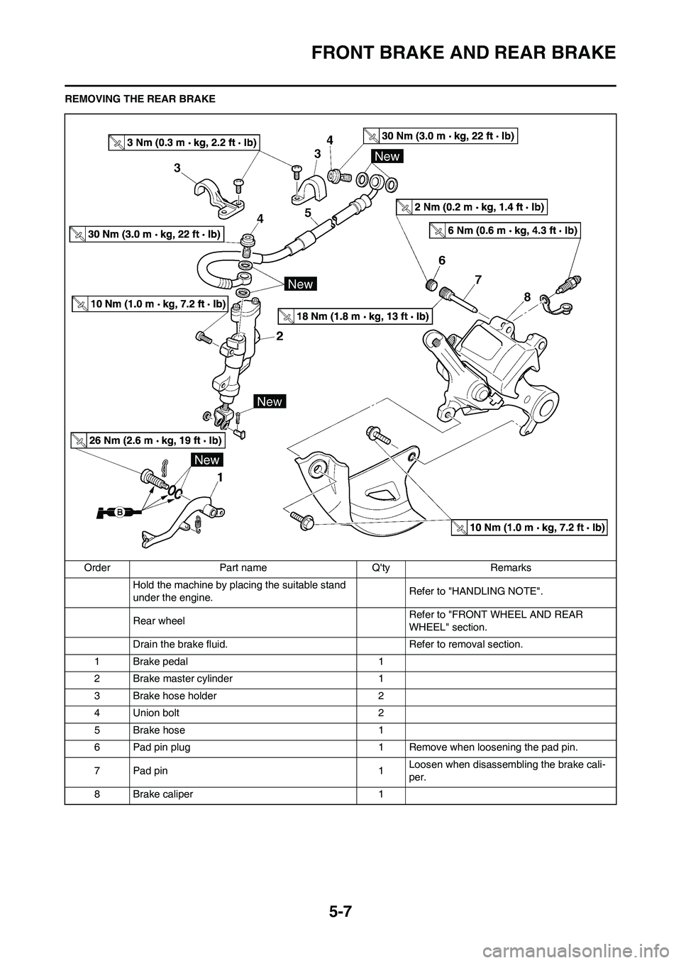
FRONT BRAKE AND REAR BRAKE
REMOVING THE REAR BRAKE
Order Part name Q'ty Remarks
Hold the machine by placing the suitable stand
under the engine.Refer to "HANDLING NOTE".
Rear wheel Refer to "FRONT WHEEL AND REAR
WHEEL" section.
Drain the brake fluid. Refer to removal section.
1 Brake pedal 1
2 Brake master cylinder 1
3 Brake hose holder 2
4 Union bolt 2
5 Brake hose 1
6 Pad pin plug 1 Remove when loosening the pad pin.
7Pad pin 1Loosen when disassembling the brake cali-
per.
8 Brake caliper 1
Page 157 of 230
5-16
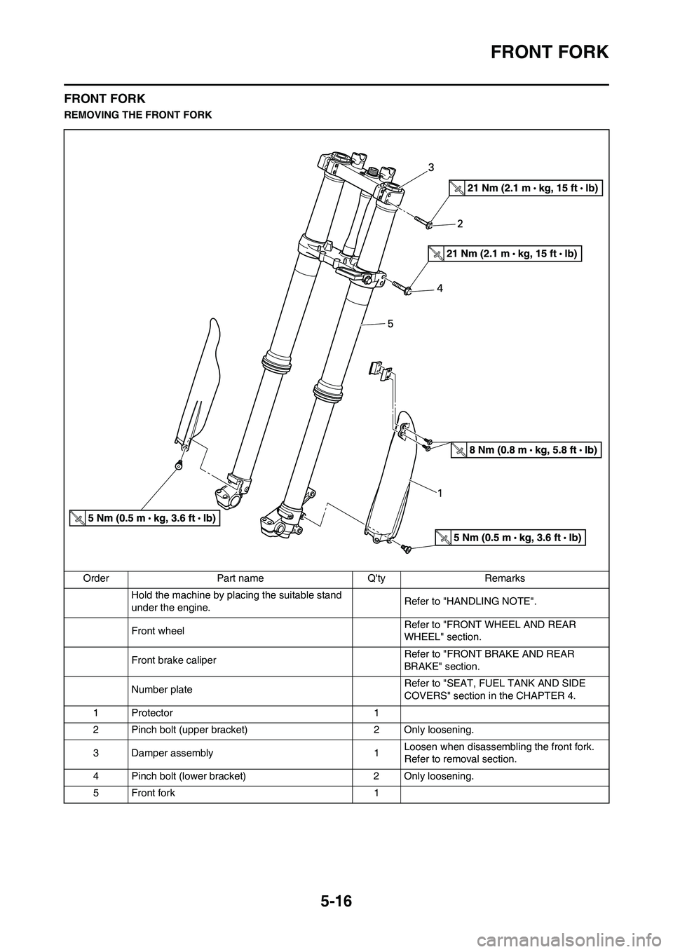
FRONT FORK
FRONT FORK
REMOVING THE FRONT FORK
Order Part name Q'ty Remarks
Hold the machine by placing the suitable stand
under the engine.Refer to "HANDLING NOTE".
Front wheel Refer to "FRONT WHEEL AND REAR
WHEEL" section.
Front brake caliper Refer to "FRONT BRAKE AND REAR
BRAKE" section.
Number plateRefer to "SEAT, FUEL TANK AND SIDE
COVERS" section in the CHAPTER 4.
1 Protector 1
2 Pinch bolt (upper bracket) 2 Only loosening.
3 Damper assembly 1Loosen when disassembling the front fork.
Refer to removal section.
4 Pinch bolt (lower bracket) 2 Only loosening.
5 Front fork 1
Page 165 of 230
5-24
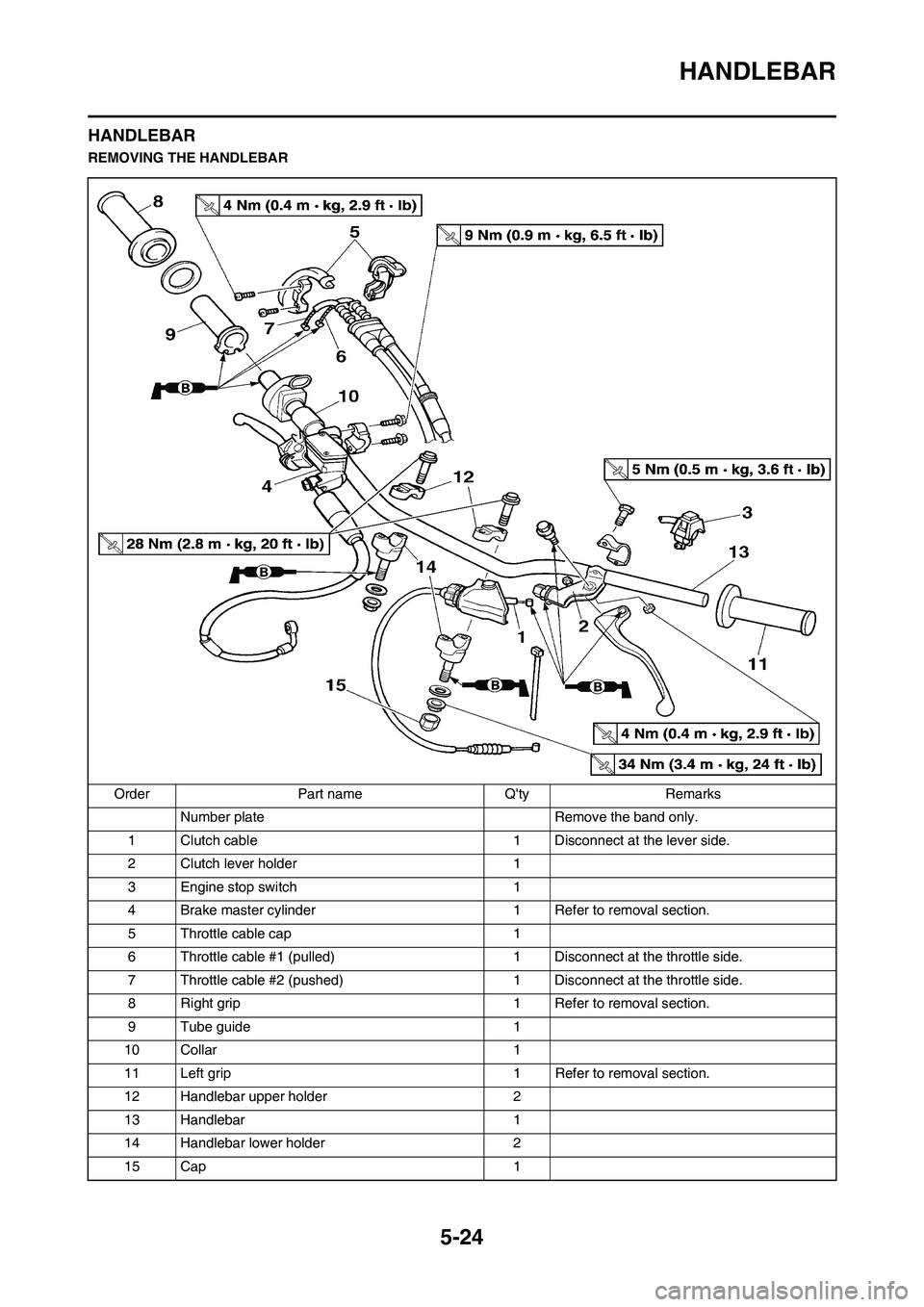
HANDLEBAR
HANDLEBAR
REMOVING THE HANDLEBAR
Order Part name Q'ty Remarks
Number plate Remove the band only.
1 Clutch cable 1 Disconnect at the lever side.
2 Clutch lever holder 1
3 Engine stop switch 1
4 Brake master cylinder 1 Refer to removal section.
5 Throttle cable cap 1
6 Throttle cable #1 (pulled) 1 Disconnect at the throttle side.
7 Throttle cable #2 (pushed) 1 Disconnect at the throttle side.
8 Right grip 1 Refer to removal section.
9 Tube guide 1
10 Collar 1
11 Left grip 1 Refer to removal section.
12 Handlebar upper holder 2
13 Handlebar 1
14 Handlebar lower holder 2
15 Cap 1
Page 168 of 230
5-27
HANDLEBAR
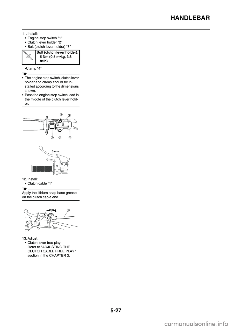
11. Install:
• Engine stop switch "1"
• Clutch lever holder "2"
• Bolt (clutch lever holder) "3"
•Clamp "4"
• The engine stop switch, clutch lever
holder and clamp should be in-
stalled according to the dimensions
shown.
• Pass the engine stop switch lead in
the middle of the clutch lever hold-
er.
12. Install:
• Clutch cable "1"
Apply the lithium soap base grease
on the clutch cable end.
13. Adjust:
• Clutch lever free play
Refer to "ADJUSTING THE
CLUTCH CABLE FREE PLAY"
section in the CHAPTER 3.Bolt (clutch lever holder):
5 Nm (0.5 m•kg, 3.6
ft•lb)
0 mm
0 mm
Page 169 of 230
5-28
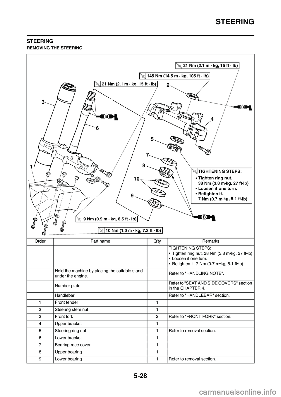
STEERING
STEERING
REMOVING THE STEERING
Order Part name Q'ty Remarks
TIGHTENING STEPS:
• Tighten ring nut. 38 Nm (3.8 m•kg, 27 ft•lb)
• Loosen it one turn.
• Retighten it. 7 Nm (0.7 m•kg, 5.1 ft•lb)
Hold the machine by placing the suitable stand
under the engine.Refer to "HANDLING NOTE".
Number plateRefer to "SEAT AND SIDE COVERS" section
in the CHAPTER 4.
Handlebar Refer to "HANDLEBAR" section.
1 Front fender 1
2 Steering stem nut 1
3 Front fork 2 Refer to "FRONT FORK" section.
4 Upper bracket 1
5 Steering ring nut 1 Refer to removal section.
6 Lower bracket 1
7 Bearing race cover 1
8 Upper bearing 1
9 Lower bearing 1 Refer to removal section.