ABS YAMAHA YZ450F 2014 Owner's Manual
[x] Cancel search | Manufacturer: YAMAHA, Model Year: 2014, Model line: YZ450F, Model: YAMAHA YZ450F 2014Pages: 360, PDF Size: 11.76 MB
Page 184 of 360
REAR SHOCK ABSORBER ASSEMBLY
4-58
EAS1SL1183INSTALLING THE REAR SHOCK ABSORB-
ER ASSEMBLY
1. Lubricate:
• Bearing (lower side)
•Dust seal
•Collars
• Bushing
ECA1DX1012
NOTICE
Do not apply the grease to the bearing outer
race because it will wear the rear shock ab
-
sorber surface on which the bearing is
press fitted.
2. Lubricate:
• O-ring
3. Install:
• Bearing
• Stopper ring
(to rear shock absorber assembly (upper
side))
TIP
• Install the bearing parallel until the stopper
ring groove appears by pressing its outer
race.
• After installing the stopper ring, push back the
bearing unit it contacts the stopper ring.
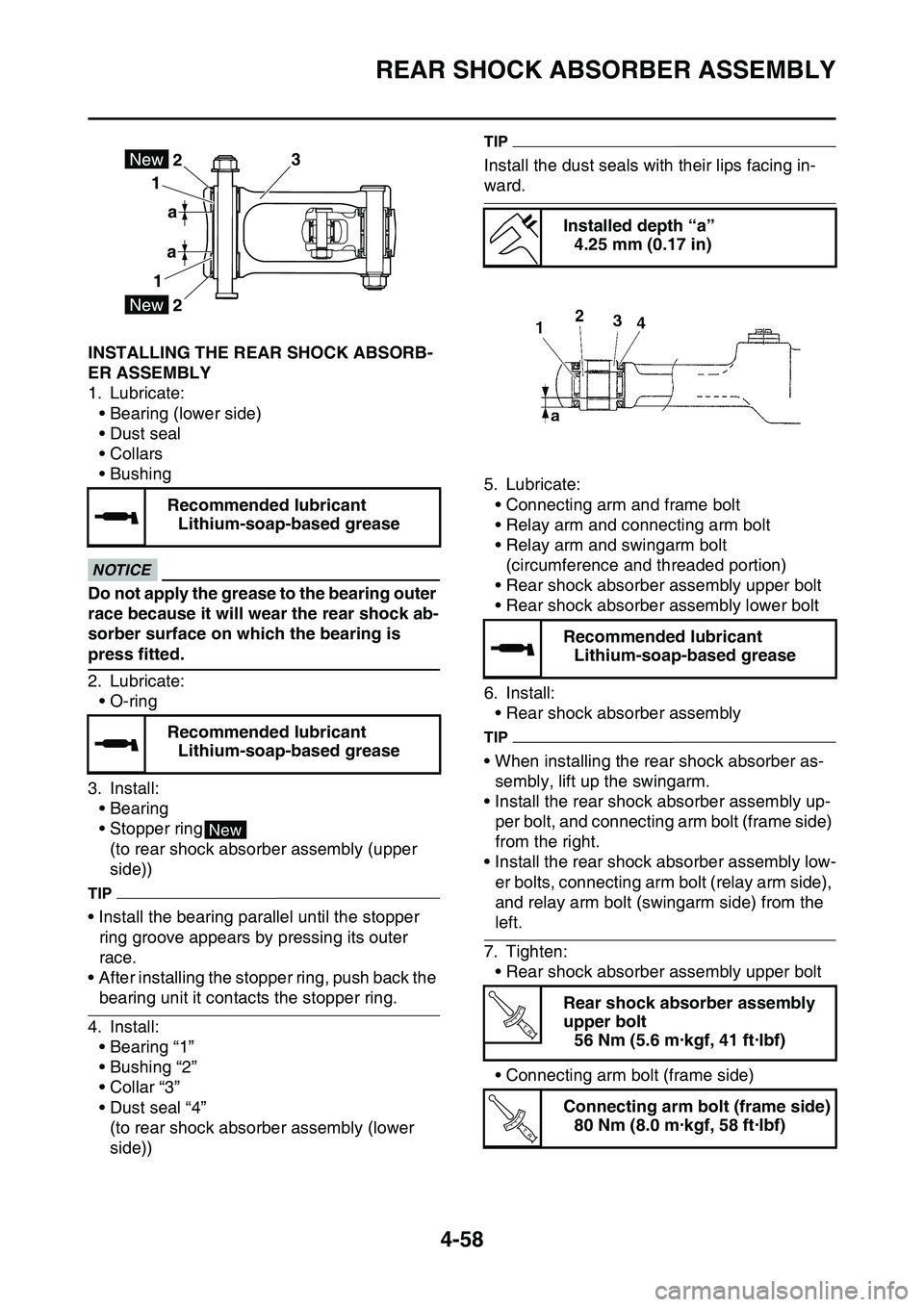
4. Install:
• Bearing “1”
• Bushing “2”
• Collar “3”
• Dust seal “4”
(to rear shock absorber assembly (lower
side))
TIP
Install the dust seals with their lips facing in-
ward.
5. Lubricate:
• Connecting arm and frame bolt
• Relay arm and connecting arm bolt
• Relay arm and swingarm bolt
(circumference and threaded portion)
• Rear shock absorber assembly upper bolt
• Rear shock absorber assembly lower bolt
6. Install:
• Rear shock absorber assembly
TIP
• When installing the rear shock absorber as-
sembly, lift up the swingarm.
• Install the rear shock absorber assembly up-
per bolt, and connecting arm bolt (frame side)
from the right.
• Install the rear shock absorber assembly low-
er bolts, connecting arm bolt (relay arm side),
and relay arm bolt (swingarm side) from the
left.
7. Tighten:
• Rear shock absorber assembly upper bolt
• Connecting arm bolt (frame side)
Recommended lubricant
Lithium-soap-based grease
Recommended lubricant
Lithium-soap-based grease
3
a 1
12
a
2
New
Installed depth “a”
4.25 mm (0.17 in)
Recommended lubricant
Lithium-soap-based grease
Rear shock absorber assembly
upper bolt
56 Nm (5.6 m·kgf, 41 ft·lbf)
Connecting arm bolt (frame side)
80 Nm (8.0 m·kgf, 58 ft·lbf)
T R..
T R..
Page 185 of 360
REAR SHOCK ABSORBER ASSEMBLY
4-59
• Connecting arm bolt (relay arm side)
• Relay arm bolt (swingarm side)
• Rear shock absorber assembly lower bolt
Connecting arm bolt (relay arm
side)
80 Nm (8.0 m·kgf, 58 ft·lbf)
Relay arm bolt (swingarm side)
70 Nm (7.0 m·kgf, 51 ft·lbf)
Rear shock absorber assembly
lower bolt
53 Nm (5.3 m·kgf, 38 ft·lbf)
T R..
T R..
T R..
Page 196 of 360
ENGINE REMOVAL
5-1
EAS1SL1195
TIP
This section is intended for those who have basic knowledge and skill concerning the servicing of
Yamaha motorcycles (e.g., Yamaha dealers, service engineers, etc.). Those who have little knowl
-
edge and skill concerning servicing are requested not to undertake inspection, adjustment, disas-
sembly, or reassembly only by reference to this manual. It may lead to servicing trouble and
mechanical damage.
EAS1SL1196
ENGINE REMOVAL
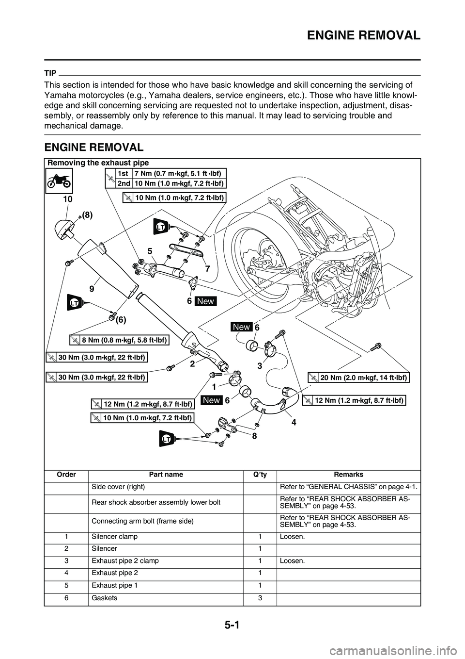
Removing the exhaust pipe
OrderPart nameQ’tyRemarks
Side cover (right)Refer to “GENERAL CHASSIS” on page 4-1.
Rear shock absorber assembly lower boltRefer to “REAR SHOCK ABSORBER AS-SEMBLY” on page 4-53.
Connecting arm bolt (frame side)Refer to “REAR SHOCK ABSORBER AS-SEMBLY” on page 4-53.
1Silencer clamp1Loosen.
2Silencer1
3Exhaust pipe 2 clamp1Loosen.
4Exhaust pipe 21
5Exhaust pipe 11
6Gaskets3
10
5
9
2 6
1
66
3
84 7 (8)
(6)
30 Nm (3.0 mkgf, 22 ftIbf)T.R.
30 Nm (3.0 mkgf, 22 ftIbf)T.R.
8 Nm (0.8 mkgf, 5.8 ftIbf)T.R.
10 Nm (1.0 mkgf, 7.2 ftIbf)T.R.
New
New
10 Nm (1.0 mkgf, 7.2 ftIbf)T.R.
12 Nm (1.2 mkgf, 8.7 ftIbf)T.R.12 Nm (1.2 mkgf, 8.7 ftIbf)T.R.
20 Nm (2.0 mkgf, 14 ftIbf)T.R.
New
1st 7 Nm (0.7 mkgf, 5.1 ftlbf)
2nd 10 Nm (1.0 m
kgf, 7.2 ftlbf)T.
R
.
LT
LT
LT
Page 201 of 360
ENGINE REMOVAL
5-6
EAS1SL1197REMOVING THE SILENCER
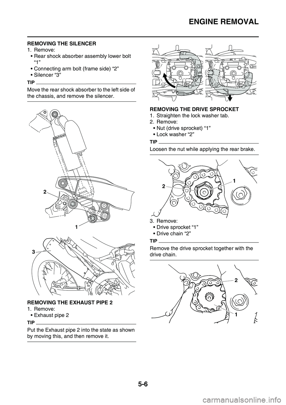
1. Remove:
• Rear shock absorber assembly lower bolt
“1”
• Connecting arm bolt (frame side) “2”
• Silencer “3”
TIP
Move the rear shock absorber to the left side of
the chassis, and remove the silencer.
EAS1SL1198REMOVING THE EXHAUST PIPE 2
1. Remove:
• Exhaust pipe 2
TIP
Put the Exhaust pipe 2 into the state as shown
by moving this, and then remove it.
EAS1SL1199REMOVING THE DRIVE SPROCKET
1. Straighten the lock washer tab.
2. Remove:
• Nut (drive sprocket) “1”
• Lock washer “2”
TIP
Loosen the nut while applying the rear brake.
3. Remove:
• Drive sprocket “1”
• Drive chain “2”
TIP
Remove the drive sprocket together with the
drive chain.
EAS1SL1200
1 2
3
Page 342 of 360
TROUBLE SHOOTING
9-3
Fuel system
1. Throttle body
• Damaged or loose throttle body joint
2. Air filter
• Clogged air filter element
Chassis
1. Brake(s)
• Dragging brake
Electrical system
1. Spark plug
• Incorrect spark plug gap
• Incorrect spark plug heat range
2. Ignition system
• Faulty ECU
• Faulty coolant temperature sensor
EAS1SL1359OVERCOOLING
Cooling system
• Faulty coolant temperature sensor
EAS1SL1360POOR BRAKING PERFORMANCE
• Worn brake pad
• Worn brake disc
• Air in hydraulic brake system
• Leaking brake fluid
• Defective master cylinder kit
• Faulty brake caliper kit
• Faulty brake caliper seal
• Loose union bolt
• Damaged brake hose
• Oil or grease on the brake disc
• Oil or grease on the brake pad
• Incorrect brake fluid level
EAS1SL1361FAULTY FRONT FORK LEGS
Leaking oil
• Bent, damaged, or rusty inner tube
• Cracked or damaged outer tube
• Improperly installed oil seal
• Damaged oil seal lip
• Incorrect oil level (high)
• Loose damper rod assembly bolt
• Damaged damper rod assembly bolt copper
washer
• Cracked or damaged cap bolt O-ring
Malfunction
• Bent or damaged inner tube
• Bent or damaged outer tube
• Broken fork spring
• Bent or damaged damper rod
• Incorrect oil viscosity
• Incorrect oil level
EAS1SL1362UNSTABLE HANDLING
1. Handlebar
• Bent or improperly installed handlebar
2. Steering head components
• Improperly installed upper bracket
• Improperly installed lower bracket
(improperly tightened ring nut)
• Bent steering stem
• Damaged ball bearing or bearing race
3. Front fork leg (s)
• Uneven oil levels (both front fork legs)
• Unevenly tensioned fork spring (both front
fork legs)
• Broken fork spring
• Bent or damaged inner tube
• Bent or damaged outer tube
4. Swingarm
• Worn bearing or bushing
• Bent or damaged swingarm
5. Rear shock absorber assembly (-ies)
• Faulty rear shock absorber spring
• Leaking oil or gas
6. Tire (s)
• Uneven tire pressures (front and rear)
• Incorrect tire pressure
• Uneven tire wear
7. Wheel (s)
• Incorrect wheel balance
• Broken or loose spoke
• Damaged wheel bearing
• Bent or loose wheel axle
• Excessive wheel runout
8. Frame
• Bent frame
• Damaged steering head pipe
• Improperly installed bearing race
Page 347 of 360
10
TUNING
CHASSIS........................................................................................................ 10-1
SELECTION OF THE SECONDARY REDUCTION
RATIO (SPROCKET) .............................................................................. 10-1
DRIVE AND REAR WHEEL SPROCKETS SETTING PARTS ................ 10-1
TIRE PRESSURE..................................................................................... 10-2
FRONT FORK SETTING.......................................................................... 10-2
CHANGE IN AMOUNT AND CHARACTERISTICS OF FORK OIL.......... 10-2
SETTING OF SPRING AFTER REPLACEMENT .................................... 10-3
FRONT FORK SETTING PARTS............................................................. 10-3
REAR SUSPENSION SETTING .............................................................. 10-3
CHOOSING SET LENGTH ...................................................................... 10-3
SETTING OF SPRING AFTER REPLACEMENT .................................... 10-4
REAR SHOCK ABSORBER SETTING PARTS ....................................... 10-5
SUSPENSION SETTING (FRONT FORK)............................................... 10-6
SUSPENSION SETTING (REAR SHOCK ABSORBER) ......................... 10-7
Page 350 of 360
CHASSIS
10-3
SETTING OF SPRING AFTER REPLACE-
MENT
As the front fork setting can be easily affected
by the rear suspension, take care so that the
front and the rear are balanced (in position etc.)
when setting the front fork.
1. Use of soft spring
• Change the rebound damping force.
Turn out one or two clicks.
• Change the compression damping force.
Turn in one or two clicks.
TIP
Generally a soft spring gives a soft riding feel-
ing. Rebound damping tends to become stron-
ger and the front fork may sink deeply over a
series of gaps.
2. Use of stiff spring
• Change the rebound damping force.
Turn in one or two clicks.
• Change the compression damping force.
Turn out one or two clicks.
TIP
Generally a stiff spring gives a stiff riding feel-
ing. Rebound damping tends to become weak-
er, resulting in lack of a sense of contact with
the road surface or in a vibrating handlebar.
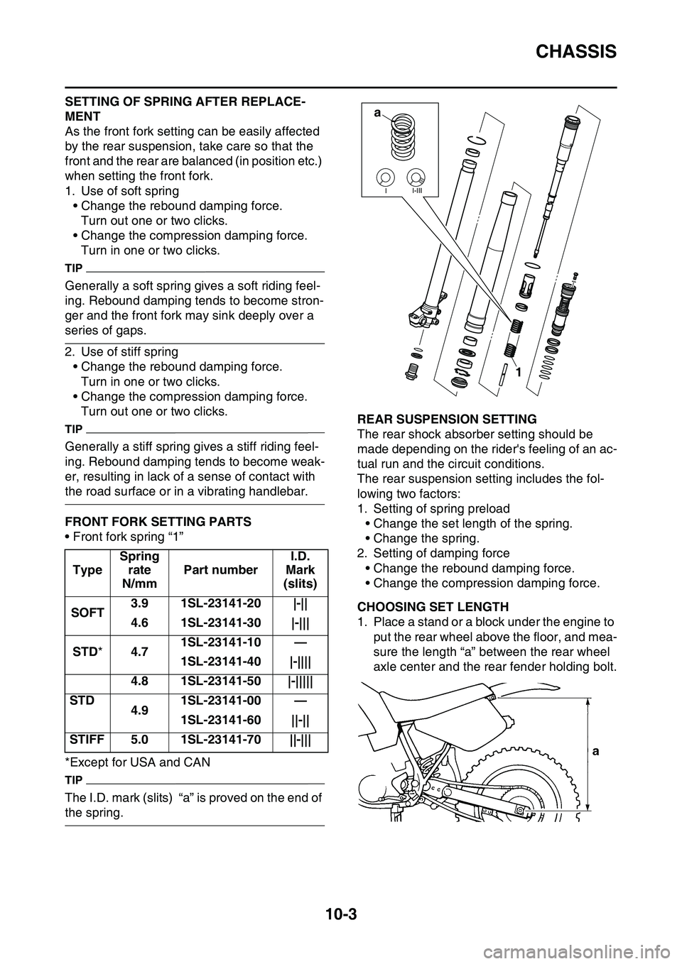
EAS1SL1372FRONT FORK SETTING PARTS
• Front fork spring “1”
*Except for USA and CAN
TIP
The I.D. mark (slits) “a” is proved on the end of
the spring.
EAS1SL1373REAR SUSPENSION SETTING
The rear shock absorber setting should be
made depending on the rider's feeling of an ac
-
tual run and the circuit conditions.
The rear suspension setting includes the fol-
lowing two factors:
1. Setting of spring preload
• Change the set length of the spring.
• Change the spring.
2. Setting of damping force
• Change the rebound damping force.
• Change the compression damping force.
EAS1SL1374CHOOSING SET LENGTH
1. Place a stand or a block under the engine to
put the rear wheel above the floor, and mea
-
sure the length “a” between the rear wheel
axle center and the rear fender holding bolt.
Type
Spring
rate
N/mm
Part number
I.D.
Mark
(slits)
SOFT3.91SL-23141-20|-||
4.61SL-23141-30|-|||
STD*4.71SL-23141-10—
1SL-23141-40|-||||
4.81SL-23141-50|-|||||
STD4.91SL-23141-00—
1SL-23141-60||-||
STIFF5.01SL-23141-70||-|||
a
1
Page 351 of 360
CHASSIS
10-4
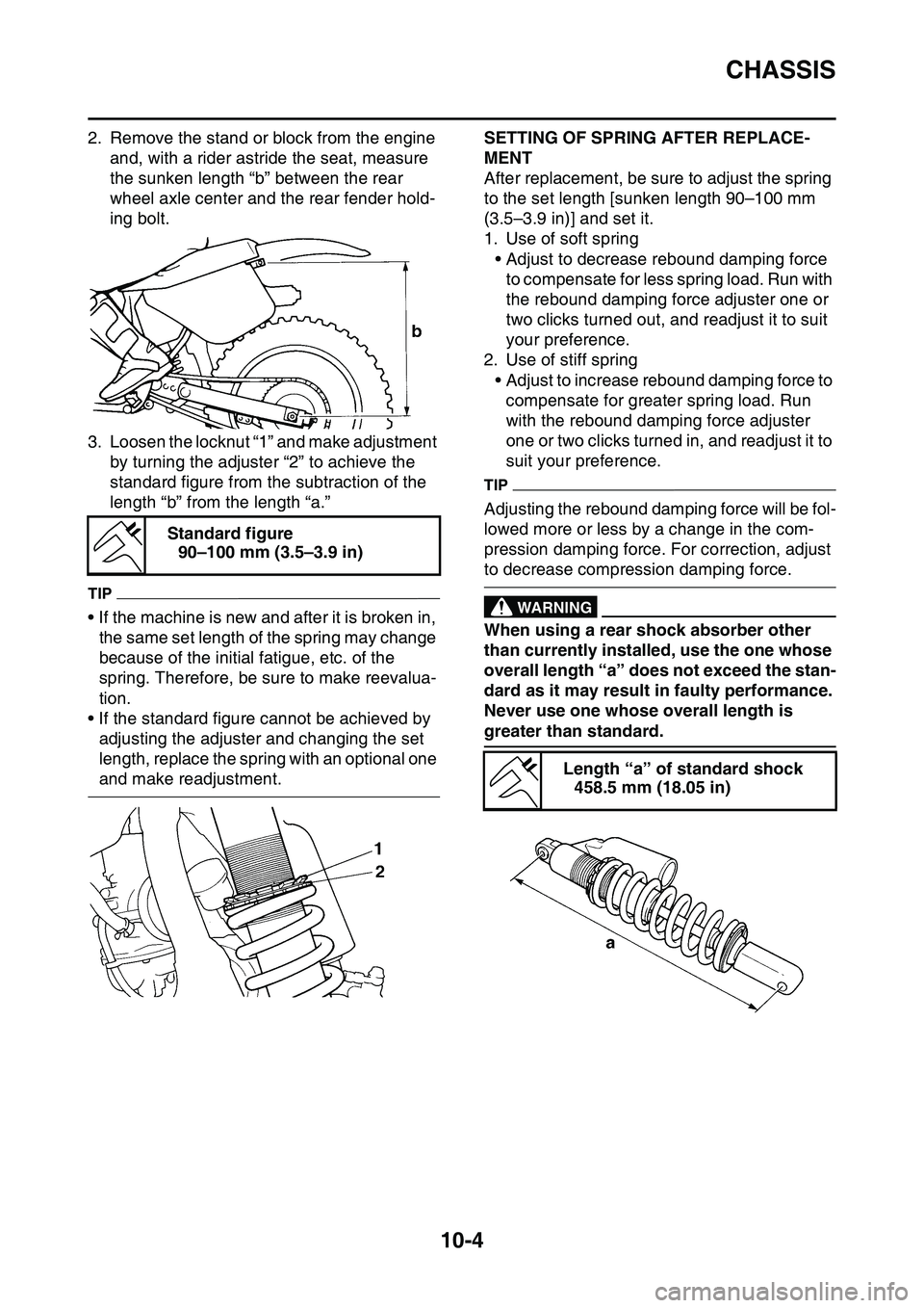
2. Remove the stand or block from the engine
and, with a rider astride the seat, measure
the sunken length “b” between the rear
wheel axle center and the rear fender hold
-
ing bolt.
3. Loosen the locknut “1” and make adjustment
by turning the adjuster “2” to achieve the
standard figure from the subtraction of the
length “b” from the length “a.”
TIP
• If the machine is new and after it is broken in,
the same set length of the spring may change
because of the initial fatigue, etc. of the
spring. Therefore, be sure to make reevalua
-
tion.
• If the standard figure cannot be achieved by
adjusting the adjuster and changing the set
length, replace the spring with an optional one
and make readjustment.
EAS1SL1375
SETTING OF SPRING AFTER REPLACE-
MENT
After replacement, be sure to adjust the spring
to the set length [sunken length 90–100 mm
(3.5–3.9 in)] and set it.
1. Use of soft spring
• Adjust to decrease rebound damping force
to compensate for less spring load. Run with
the rebound damping force adjuster one or
two clicks turned out, and readjust it to suit
your preference.
2. Use of stiff spring
• Adjust to increase rebound damping force to
compensate for greater spring load. Run
with the rebound damping force adjuster
one or two clicks turned in, and readjust it to
suit your preference.
TIP
Adjusting the rebound damping force will be fol-
lowed more or less by a change in the com-
pression damping force. For correction, adjust
to decrease compression damping force.
EWA1DX4002
WARNING
When using a rear shock absorber other
than currently installed, use the one whose
overall length “a” does not exceed the stan
-
dard as it may result in faulty performance.
Never use one whose overall length is
greater than standard.
EAS1SL1376
Standard figure
90–100 mm (3.5–3.9 in)
Length “a” of standard shock
458.5 mm (18.05 in)
Page 352 of 360
CHASSIS
10-5
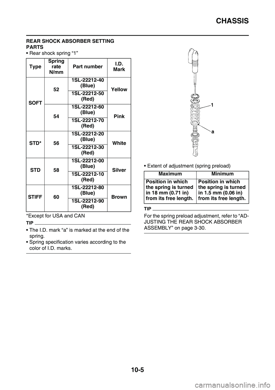
REAR SHOCK ABSORBER SETTING
PARTS
• Rear shock spring “1”
*Except for USA and CAN
TIP
• The I.D. mark “a” is marked at the end of the
spring.
• Spring specification varies according to the
color of I.D. marks.
• Extent of adjustment (spring preload)
TIP
For the spring preload adjustment, refer to “AD-
JUSTING THE REAR SHOCK ABSORBER
ASSEMBLY” on page 3-30.
Type
Spring
rate
N/mm
Part numberI.D.
Mark
SOFT
52
1SL-22212-40
(Blue)
Yellow1SL-22212-50
(Red)
54
1SL-22212-60
(Blue)
Pink1SL-22212-70
(Red)
STD*56
1SL-22212-20
(Blue)
White1SL-22212-30
(Red)
STD58
1SL-22212-00
(Blue)
Silver1SL-22212-10
(Red)
STIFF60
1SL-22212-80
(Blue)
Brown1SL-22212-90
(Red)
MaximumMinimum
Position in which
the spring is turned
in 18 mm (0.71 in)
from its free length.Position in which
the spring is turned
in 1.5 mm (0.06 in)
from its free length.
Page 353 of 360
CHASSIS
10-6
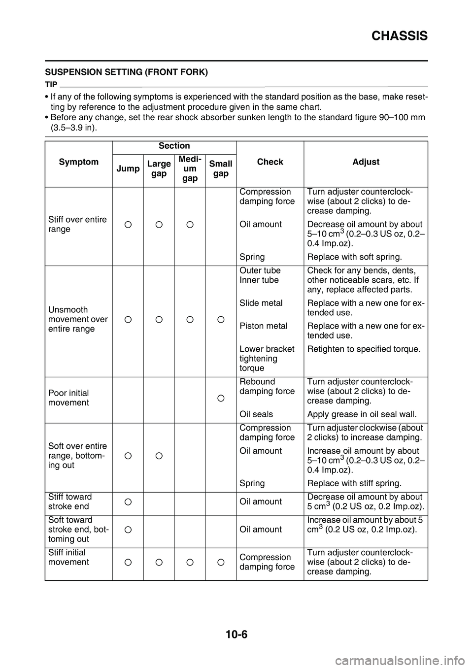
EAS1SL1377SUSPENSION SETTING (FRONT FORK)
TIP
• If any of the following symptoms is experienced with the standard position as the base, make reset-
ting by reference to the adjustment procedure given in the same chart.
• Before any change, set the rear shock absorber sunken length to the standard figure 90–100 mm
(3.5–3.9 in).
Symptom
Section
CheckAdjustJumpLarge
gapMedi-
um
gapSmall
gap
Stiff over entire
range
Compression
damping forceTurn adjuster counterclock-
wise (about 2 clicks) to de-
crease damping.
Oil amountDecrease oil amount by about
5–10 cm3 (0.2–0.3 US oz, 0.2–
0.4 Imp.oz).
SpringReplace with soft spring.
Unsmooth
movement over
entire range
Outer tube
Inner tube
Check for any bends, dents,
other noticeable scars, etc. If
any, replace affected parts.
Slide metalReplace with a new one for ex-
tended use.
Piston metalReplace with a new one for ex-
tended use.
Lower bracket
tightening
torqueRetighten to specified torque.
Poor initial
movement
Rebound
damping forceTurn adjuster counterclock-
wise (about 2 clicks) to de-
crease damping.
Oil sealsApply grease in oil seal wall.
Soft over entire
range, bottom
-
ing out
Compression
damping forceTurn adjuster clockwise (about
2 clicks) to increase damping.
Oil amountIncrease oil amount by about
5–10 cm3 (0.2–0.3 US oz, 0.2–
0.4 Imp.oz).
SpringReplace with stiff spring.
Stiff toward
stroke endOil amountDecrease oil amount by about
5 cm3 (0.2 US oz, 0.2 Imp.oz).
Soft toward
stroke end, bot
-
toming out
Oil amount
Increase oil amount by about 5
cm3 (0.2 US oz, 0.2 Imp.oz).
Stiff initial
movementCompression
damping forceTurn adjuster counterclock-
wise (about 2 clicks) to de-
crease damping.