Chain YAMAHA YZ450F 2015 User Guide
[x] Cancel search | Manufacturer: YAMAHA, Model Year: 2015, Model line: YZ450F, Model: YAMAHA YZ450F 2015Pages: 360, PDF Size: 10.82 MB
Page 63 of 360

TIGHTENING TORQUES
2-20
TIP
1. First, tighten the lower ring nut approximately 38 Nm (3.8 m·kgf, 27 ft·lbf) by using the steering nut
wrench, then loosen the lower ring nut one turn.
2. Retighten the lower ring nut 7 Nm (0.7 m·kgf, 5.1 ft·lbf).Drive chain tensioner bolt (lower
side)M8 1 16 Nm (1.6 m·kgf, 12 ft·lbf)
Drive chain support bolt M6 1 7 Nm (0.7 m·kgf, 5.1 ft·lbf)
Drive chain support nut M6 2 7 Nm (0.7 m·kgf, 5.1 ft·lbf)
Drive chain guide bolt M5 3 4.0 Nm (0.40 m·kgf, 2.9 ft·lbf)
Rear frame and left cover bolt M6 2 7 Nm (0.7 m·kgf, 5.1 ft·lbf)
Fuel tank bolt (front side) M6 2 7 Nm (0.7 m·kgf, 5.1 ft·lbf)
Fuel tank bolt (rear side) M6 1 9 Nm (0.9 m·kgf, 6.5 ft·lbf)
Fuel tank bracket bolt (front side) M6 4 7 Nm (0.7 m·kgf, 5.1 ft·lbf)
Fuel tank bracket bolt (rear side) M6 2 7 Nm (0.7 m·kgf, 5.1 ft·lbf)
Fuel pump bolt M5 6 4.0 Nm (0.40 m·kgf, 2.9 ft·lbf)
Fuel inlet pipe screw M5 2 3.4 Nm (0.34 m·kgf, 2.5 ft·lbf)
Fuel tank cap cover bolt M6 2 4.0 Nm (0.40 m·kgf, 2.9 ft·lbf)
Seat set bracket and fuel tank screw M6 1 7 Nm (0.7 m·kgf, 5.1 ft·lbf)
Seat bolt M8 2 22 Nm (2.2 m·kgf, 16 ft·lbf)
Left side cover bolt M6 1 7 Nm (0.7 m·kgf, 5.1 ft·lbf)
Right side cover bolt M6 2 7 Nm (0.7 m·kgf, 5.1 ft·lbf)
Frame and air scoop bolt M6 2 7 Nm (0.7 m·kgf, 5.1 ft·lbf)
Fuel tank and air scoop bolt M6 2 7 Nm (0.7 m·kgf, 5.1 ft·lbf)
Radiator guard and air scoop bolt M6 4 7 Nm (0.7 m·kgf, 5.1 ft·lbf)
Front fender bolt M6 4 10 Nm (1.0 m·kgf, 7.2 ft·lbf)
Rear fender bolt (front side) M6 4 7 Nm (0.7 m·kgf, 5.1 ft·lbf)
Rear fender bolt (rear side) M6 2 16 Nm (1.6 m·kgf, 12 ft·lbf)
Mud flap screw — 2 1.3 Nm (0.13 m·kgf, 0.94 ft·lbf)
Number plate bolt M6 1 7 Nm (0.7 m·kgf, 5.1 ft·lbf)ITEMThread
sizeQ’ty TIGHTENING TORQUES Remarks
Page 87 of 360
3
PERIODIC CHECKS AND ADJUSTMENTS
MAINTENANCE INTERVALS.......................................................................... 3-1
MAINTENANCE INTERVALS .................................................................... 3-1
PRE-OPERATION INSPECTION AND MAINTENANCE................................. 3-7
GENERAL INSPECTION AND MAINTENANCE........................................ 3-7
ENGINE............................................................................................................ 3-8
CHECKING THE COOLANT LEVEL .......................................................... 3-8
CHECKING THE COOLING SYSTEM ....................................................... 3-8
CHANGING THE COOLANT...................................................................... 3-8
CHECKING THE RADIATOR CAP ............................................................ 3-9
CHECKING THE RADIATOR CAP OPENING PRESSURE ...................... 3-9
CHECKING THE COOLANT CIRCULATORY SYSTEM FOR LEAKS .... 3-10
ADJUSTING THE CLUTCH LEVER POSITION ...................................... 3-10
ADJUSTING THE CLUTCH LEVER FREE PLAY .................................... 3-10
ADJUSTING THE THROTTLE GRIP FREE PLAY .................................. 3-11
LUBRICATING THE THROTTLE CABLE ................................................ 3-12
CLEANING THE AIR FILTER ELEMENT................................................. 3-12
CHECKING THE THROTTLE BODY JOINT ............................................ 3-13
CHECKING THE BREATHER HOSES .................................................... 3-13
CHECKING THE EXHAUST SYSTEM..................................................... 3-13
CHECKING THE FUEL LINE ................................................................... 3-14
CHECKING THE ENGINE OIL LEVEL..................................................... 3-14
CHANGING THE ENGINE OIL ................................................................ 3-15
ADJUSTING THE ENGINE IDLING SPEED ............................................ 3-16
ADJUSTING THE VALVE CLEARANCE ................................................. 3-17
CHASSIS........................................................................................................ 3-21
BLEEDING THE BRAKE SYSTEM .......................................................... 3-21
CHECKING THE BRAKE HOSE .............................................................. 3-22
ADJUSTING THE FRONT BRAKE .......................................................... 3-22
ADJUSTING THE REAR BRAKE ............................................................. 3-23
CHECKING THE FRONT BRAKE PADS ................................................. 3-23
CHECKING THE REAR BRAKE PADS ................................................... 3-25
CHECKING THE REAR BRAKE PAD INSULATOR ................................ 3-26
CHECKING THE BRAKE FLUID LEVEL.................................................. 3-26
ADJUSTING THE DRIVE CHAIN SLACK ................................................ 3-27
CHECKING THE FRONT FORK LEGS ................................................... 3-28
CHECKING THE FRONT FORK PROTECTOR GUIDE .......................... 3-28
CLEANING THE FRONT FORK OIL SEAL AND DUST SEAL ................ 3-28
AIR BLEEDING FROM FRONT FORK .................................................... 3-28
ADJUSTING THE FRONT FORK LEGS .................................................. 3-29
CHECKING THE SWINGARM OPERATION ........................................... 3-30
CHECKING THE REAR SUSPENSION ................................................... 3-30
ADJUSTING THE REAR SHOCK ABSORBER ASSEMBLY ................... 3-30
CHECKING THE TIRES ........................................................................... 3-32
CHECKING AND TIGHTENING THE SPOKES ....................................... 3-32
CHECKING THE WHEELS ...................................................................... 3-33
Page 93 of 360

MAINTENANCE INTERVALS
3-5
Replace brake flu-
idEvery one year
SWINGARM
Inspect, lube and
retightenMolybdenum disulfide grease
RELAY ARM, CON-
NECTING ROD
Inspect, lube and
retightenMolybdenum disulfide grease
STEERING HEAD
Inspect free play
and retightenCheck for tightening torques.
Clean and lube After rain ride
Replace bearings
TIRE, WHEELS
Inspect air pres-
sure, wheel run-
out, tire wear and
spoke looseness
Retighten sprocket
bolt
Check the bearing
Replace bearings
Lubricate Lithium soap base grease
DRIVE CHAIN Use chain oil.
Clean, lubricate,
slack, alignment
Replace
DRIVE CHAIN
GUIDE
Inspect Inspect wear.
DRIVE CHAIN
GUIDE AND DRIVE
CHAIN SUPPORT
Replace
CABLES
Routing (Connec-
tion)
Check and grease
Check and clean
throttle cableCheck throttle cables on the
throttle body for dirt and wear. ITEMAfter
break-
inEvery
race
(about
2.5
hours)Every
third
(about
7.5
hours)Every
fifth
(about
12.5
hours)As re-
quiredRemarks
Page 95 of 360
PRE-OPERATION INSPECTION AND MAINTENANCE
3-7
EAS1SL5068
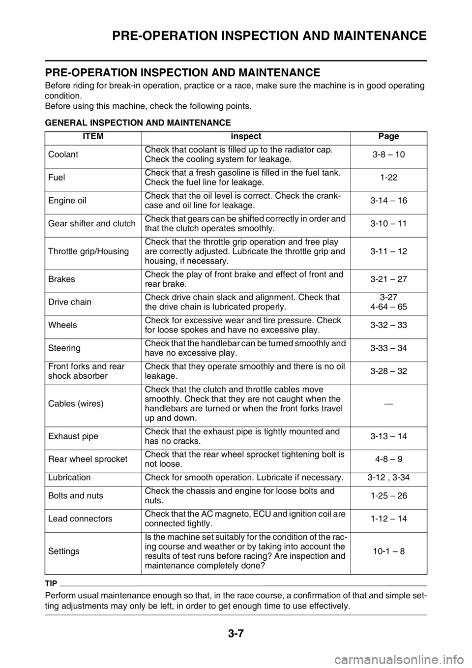
PRE-OPERATION INSPECTION AND MAINTENANCE
Before riding for break-in operation, practice or a race, make sure the machine is in good operating
condition.
Before using this machine, check the following points.
EAS1SL5069GENERAL INSPECTION AND MAINTENANCE
TIP
Perform usual maintenance enough so that, in the race course, a confirmation of that and simple set-
ting adjustments may only be left, in order to get enough time to use effectively.ITEM inspect Page
CoolantCheck that coolant is filled up to the radiator cap.
Check the cooling system for leakage.3-8 – 10
FuelCheck that a fresh gasoline is filled in the fuel tank.
Check the fuel line for leakage.1-22
Engine oilCheck that the oil level is correct. Check the crank-
case and oil line for leakage.3-14 – 16
Gear shifter and clutchCheck that gears can be shifted correctly in order and
that the clutch operates smoothly.3-10 – 11
Throttle grip/HousingCheck that the throttle grip operation and free play
are correctly adjusted. Lubricate the throttle grip and
housing, if necessary.3-11 – 12
BrakesCheck the play of front brake and effect of front and
rear brake.3-21 – 27
Drive chainCheck drive chain slack and alignment. Check that
the drive chain is lubricated properly.3-27
4-64 – 65
WheelsCheck for excessive wear and tire pressure. Check
for loose spokes and have no excessive play.3-32 – 33
SteeringCheck that the handlebar can be turned smoothly and
have no excessive play.3-33 – 34
Front forks and rear
shock absorberCheck that they operate smoothly and there is no oil
leakage.3-28 – 32
Cables (wires)Check that the clutch and throttle cables move
smoothly. Check that they are not caught when the
handlebars are turned or when the front forks travel
up and down.—
Exhaust pipeCheck that the exhaust pipe is tightly mounted and
has no cracks.3-13 – 14
Rear wheel sprocketCheck that the rear wheel sprocket tightening bolt is
not loose.4-8 – 9
Lubrication Check for smooth operation. Lubricate if necessary. 3-12 , 3-34
Bolts and nutsCheck the chassis and engine for loose bolts and
nuts.1-25 – 26
Lead connectorsCheck that the AC magneto, ECU and ignition coil are
connected tightly.1-12 – 14
SettingsIs the machine set suitably for the condition of the rac-
ing course and weather or by taking into account the
results of test runs before racing? Are inspection and
maintenance completely done?10-1 – 8
Page 106 of 360

ENGINE
3-18
TIP
Check that the alignment mark “c” on the cam-
shaft sprocket and the alignment mark “d” on
the intake camshaft sprocket are aligned with
the edge of the cylinder head.
c. Measure the valve clearance “e” using a
thickness gauge “1”.
TIP
Record the measured reading if the clearance
is incorrect.
▲▲▲▲▲▲▲▲▲▲▲▲▲▲▲▲▲▲▲▲▲▲▲▲▲▲▲▲▲▲▲▲
5. Adjust:
• Valve clearance
▼▼▼▼▼▼▼▼▼▼▼▼▼▼▼▼▼▼▼▼▼▼▼▼▼▼▼▼▼▼▼▼
a. Remove the camshaft (intake and exhaust).
Refer to “CAMSHAFT” on page 5-11.
b. Remove the valve lifter “2” and the adjusting
pad “3” with a valve lapper “1”.
TIP
• Place a cloth in the timing chain space to pre-
vent adjusting pads from falling into the crank-
case.
• Identity each valve lifter and adjusting pad po-
sition very carefully so that they can be rein-
stalled in their original place.
c. Check the number on the originally installed
adjusting pad.
TIP
• The adjusting pad number “a” is indicated on
the top of the adjusting pad.
• For the number on the originally installed ad-
justing pad, convert the last digit of adjusting
pad number as per the below table.
b
a
dc
ee
1
Valve lapper
90890-04101
Valve lapping tool
YM-A8998
1
32
Page 115 of 360
CHASSIS
3-27
WARNING
• Use only the designated brake fluid. Other
brake fluids may cause the rubber seals to
deteriorate, causing leakage and poor
brake performance.
• Refill with the same type of brake fluid that
is already in the system. Mixing brake flu-
ids may result in a harmful chemical reac-
tion, leading to poor brake performance.
• When refilling, be careful that water does
not enter the brake fluid reservoir. Water
will significantly lower the boiling point of
the brake fluid and could cause vapor
lock.
ECA13540
NOTICE
Brake fluid may damage painted surfaces
and plastic parts. Therefore, always clean
up any spilt brake fluid immediately.
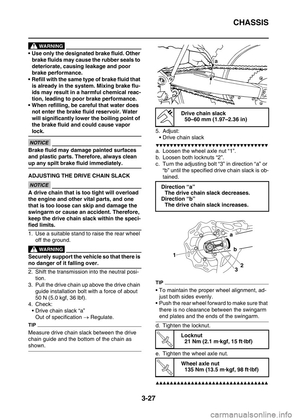
EAS1SL5099ADJUSTING THE DRIVE CHAIN SLACKECA13550
NOTICE
A drive chain that is too tight will overload
the engine and other vital parts, and one
that is too loose can skip and damage the
swingarm or cause an accident. Therefore,
keep the drive chain slack within the speci-
fied limits.
1. Use a suitable stand to raise the rear wheel
off the ground.
EWA13120
WARNING
Securely support the vehicle so that there is
no danger of it falling over.
2. Shift the transmission into the neutral posi-
tion.
3. Pull the drive chain up above the drive chain
guide installation bolt with a force of about
50 N (5.0 kgf, 36 lbf).
4. Check:
• Drive chain slack “a”
Out of specification Regulate.
TIP
Measure drive chain slack between the drive
chain guide and the bottom of the chain as
shown.5. Adjust:
• Drive chain slack
▼▼▼▼▼▼▼▼▼▼▼▼▼▼▼▼▼▼▼▼▼▼▼▼▼▼▼▼▼▼▼▼
a. Loosen the wheel axle nut “1”.
b. Loosen both locknuts “2”.
c. Turn the adjusting bolt “3” in direction “a” or
“b” until the specified drive chain slack is ob-
tained.
TIP
• To maintain the proper wheel alignment, ad-
just both sides evenly.
• Push the rear wheel forward to make sure that
there is no clearance between the swingarm
end plates and the ends of the swingarm.
d. Tighten the locknut.
e. Tighten the wheel axle nut.
▲▲▲▲▲▲▲▲▲▲▲▲▲▲▲▲▲▲▲▲▲▲▲▲▲▲▲▲▲▲▲▲
Drive chain slack
50–60 mm (1.97–2.36 in)
Direction “a”
The drive chain slack decreases.
Direction “b”
The drive chain slack increases.
Locknut
21 Nm (2.1 m·kgf, 15 ft·lbf)
Wheel axle nut
135 Nm (13.5 m·kgf, 98 ft·lbf)
a
1
32
a
b
T R..
T R..
Page 126 of 360

HANDLEBAR................................................................................................. 4-31
REMOVING THE HANDLEBAR............................................................... 4-33
CHECKING THE HANDLEBAR ............................................................... 4-33
INSTALLING THE HANDLEBAR ............................................................. 4-33
FRONT FORK................................................................................................. 4-37
REMOVING THE FRONT FORK LEGS ................................................... 4-39
DISASSEMBLING THE FRONT FORK LEGS ......................................... 4-39
CHECKING THE FRONT FORK LEGS ................................................... 4-40
ASSEMBLING THE FRONT FORK LEGS ............................................... 4-41
INSTALLING THE FRONT FORK LEGS ................................................. 4-47
STEERING HEAD........................................................................................... 4-49
REMOVING THE LOWER BRACKET...................................................... 4-50
CHECKING THE STEERING HEAD ........................................................ 4-50
INSTALLING THE STEERING HEAD ...................................................... 4-50
REAR SHOCK ABSORBER ASSEMBLY..................................................... 4-53
HANDLING THE REAR SHOCK ABSORBER ......................................... 4-56
DISPOSING OF A REAR SHOCK ABSORBER ...................................... 4-56
REMOVING THE REAR SHOCK ABSORBER ASSEMBLY.................... 4-56
REMOVING THE BEARING..................................................................... 4-56
CHECKING THE REAR SHOCK ABSORBER ASSEMBLY .................... 4-57
CHECKING THE CONNECTING ARM AND RELAY ARM ...................... 4-57
INSTALLING THE RELAY ARM............................................................... 4-57
INSTALLING THE REAR SHOCK ABSORBER ASSEMBLY .................. 4-58
SWINGARM.................................................................................................... 4-60
REMOVING THE SWINGARM................................................................. 4-61
REMOVING THE BEARING..................................................................... 4-61
CHECKING THE SWINGARM ................................................................. 4-61
INSTALLING THE SWINGARM ............................................................... 4-62
CHAIN DRIVE................................................................................................. 4-63
REMOVING THE DRIVE CHAIN.............................................................. 4-64
CHECKING THE DRIVE CHAIN .............................................................. 4-64
CHECKING THE DRIVE SPROCKET...................................................... 4-65
CHECKING THE REAR WHEEL SPROCKET ......................................... 4-65
INSTALLING THE DRIVE CHAIN ............................................................ 4-65
Page 133 of 360

REAR WHEEL
4-7
EAS1SL5129
REAR WHEEL
Removing the rear wheel
Order Part name Q’ty Remarks
Use a suitable stand to raise the rear wheel
off the ground.
1 Nut (rear wheel axle) 1
2 Rear wheel axle 1
3 Drive chain puller 2
4 Rear wheel 1
5Collars 2
6 Rear wheel sprocket 1
7Oil seals 2
8 Circlip 1
9 Bearing 3
10 Brake disc 1
For installation, reverse the removal proce-
dure.
(6)
21 Nm (2.1 m•kgf, 15 ft•Ibf)T.R.
2 5
7 9
LS
LS(6)
46
1
(6) 3
LS
8
9 10
7 5
LT
14 Nm (1.4 m•kgf, 10 ft•Ibf)T.R.
3
21 Nm (2.1 m•kgf, 15 ft•Ibf)T.R.
42 Nm (4.2 m•kgf, 30 ft•Ibf)T.R.
135 Nm (13.5 m•kgf, 98 ft•lbf)T.R.
Page 134 of 360
REAR WHEEL
4-8
EAS1SL5130REMOVING THE REAR WHEEL
1. Use a suitable stand to raise the rear wheel
off the ground.
EWA13120
WARNING
Securely support the vehicle so that there is
no danger of it falling over.
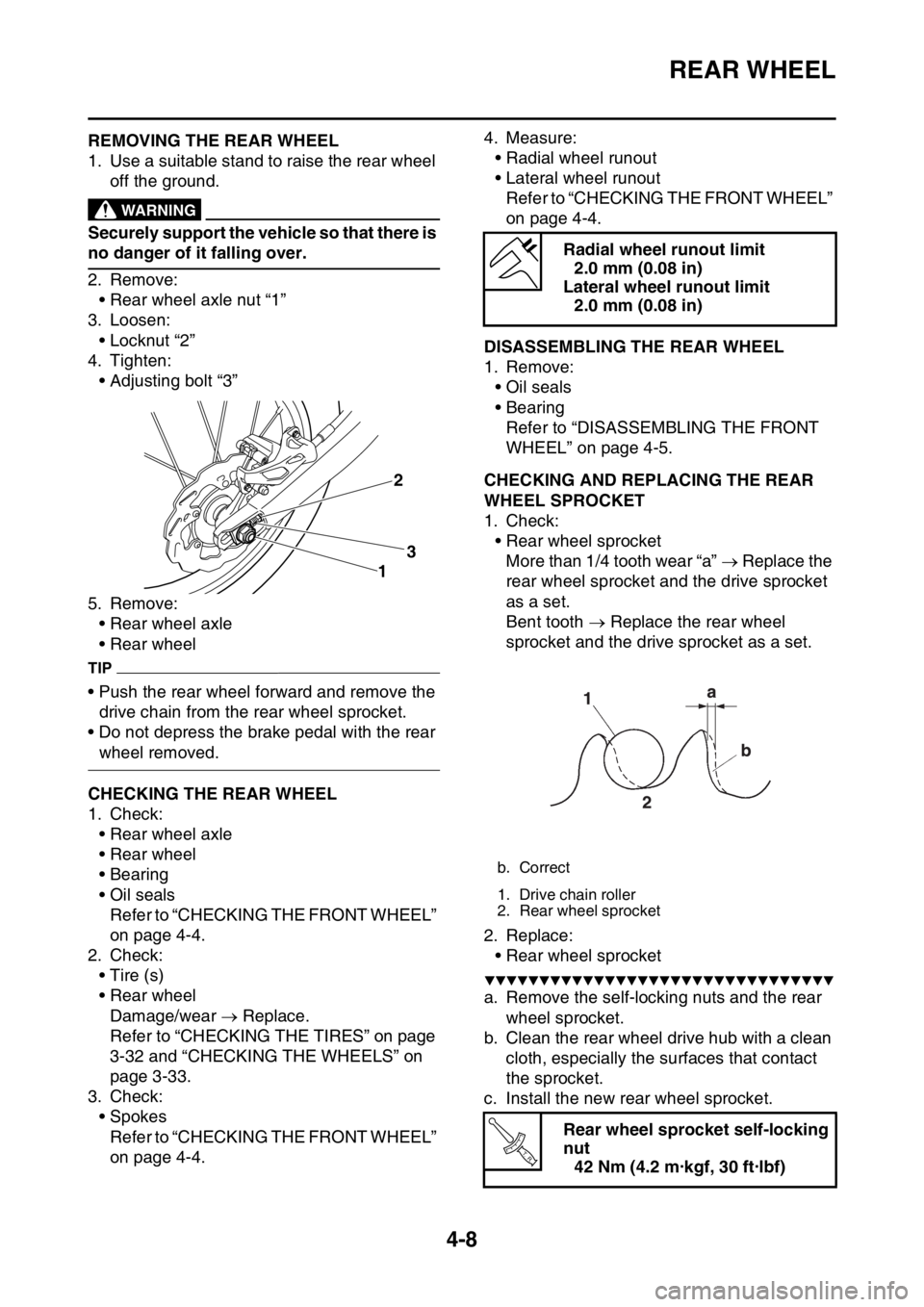
2. Remove:
• Rear wheel axle nut “1”
3. Loosen:
• Locknut “2”
4. Tighten:
• Adjusting bolt “3”
5. Remove:
• Rear wheel axle
• Rear wheel
TIP
• Push the rear wheel forward and remove the
drive chain from the rear wheel sprocket.
• Do not depress the brake pedal with the rear
wheel removed.
EAS1SL5131CHECKING THE REAR WHEEL
1. Check:
• Rear wheel axle
• Rear wheel
• Bearing
• Oil seals
Refer to “CHECKING THE FRONT WHEEL”
on page 4-4.
2. Check:
•Tire (s)
• Rear wheel
Damage/wear Replace.
Refer to “CHECKING THE TIRES” on page
3-32 and “CHECKING THE WHEELS” on
page 3-33.
3. Check:
• Spokes
Refer to “CHECKING THE FRONT WHEEL”
on page 4-4.4. Measure:
• Radial wheel runout
• Lateral wheel runout
Refer to “CHECKING THE FRONT WHEEL”
on page 4-4.
EAS1SL5132DISASSEMBLING THE REAR WHEEL
1. Remove:
• Oil seals
• Bearing
Refer to “DISASSEMBLING THE FRONT
WHEEL” on page 4-5.
EAS1SL5133CHECKING AND REPLACING THE REAR
WHEEL SPROCKET
1. Check:
• Rear wheel sprocket
More than 1/4 tooth wear “a” Replace the
rear wheel sprocket and the drive sprocket
as a set.
Bent tooth Replace the rear wheel
sprocket and the drive sprocket as a set.
2. Replace:
• Rear wheel sprocket
▼▼▼▼▼▼▼▼▼▼▼▼▼▼▼▼▼▼▼▼▼▼▼▼▼▼▼▼▼▼▼▼
a. Remove the self-locking nuts and the rear
wheel sprocket.
b. Clean the rear wheel drive hub with a clean
cloth, especially the surfaces that contact
the sprocket.
c. Install the new rear wheel sprocket.
3
12
Radial wheel runout limit
2.0 mm (0.08 in)
Lateral wheel runout limit
2.0 mm (0.08 in)
b. Correct
1. Drive chain roller
2. Rear wheel sprocket
Rear wheel sprocket self-locking
nut
42 Nm (4.2 m·kgf, 30 ft·lbf)
T R..
Page 136 of 360
REAR WHEEL
4-10
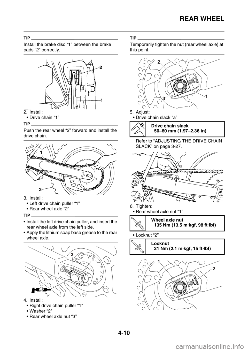
TIP
Install the brake disc “1” between the brake
pads “2” correctly.
2. Install:
• Drive chain “1”
TIP
Push the rear wheel “2” forward and install the
drive chain.
3. Install:
• Left drive chain puller “1”
• Rear wheel axle “2”
TIP
• Install the left drive chain puller, and insert the
rear wheel axle from the left side.
• Apply the lithium soap base grease to the rear
wheel axle.
4. Install:
• Right drive chain puller “1”
• Washer “2”
• Rear wheel axle nut “3”
TIP
Temporarily tighten the nut (rear wheel axle) at
this point.
5. Adjust:
• Drive chain slack “a”
Refer to “ADJUSTING THE DRIVE CHAIN
SLACK” on page 3-27.
6. Tighten:
• Rear wheel axle nut “1”
• Locknut “2”
1 2
LS
Drive chain slack
50–60 mm (1.97–2.36 in)
Wheel axle nut
135 Nm (13.5 m·kgf, 98 ft·lbf)
Locknut
21 Nm (2.1 m·kgf, 15 ft·lbf)
2
1
3
a
T R..
T R..
1
2