Chain YAMAHA YZ450F 2015 Owner's Manual
[x] Cancel search | Manufacturer: YAMAHA, Model Year: 2015, Model line: YZ450F, Model: YAMAHA YZ450F 2015Pages: 360, PDF Size: 10.82 MB
Page 186 of 360

SWINGARM
4-60
EAS1SL5185
SWINGARM
Removing the swingarm
Order Part name Q’ty Remarks
Use a suitable stand to raise the front wheel
off the ground.
Brake hose holder Refer to “REAR BRAKE” on page 4-21.
Rear brake caliper Refer to “REAR BRAKE” on page 4-21.
Bolt (brake pedal)
Drive chain
1Collars 2
2Oil seals 2
3Thrust bearing 2
4Bushing 2
5Oil seals 2
6 Bearing 4
For installation, reverse the removal proce-
dure.
1
2
3
6
4
6
4
1
3
6
2
5
T.R.70 Nm (7.0 mlbf) kgf, 51 ft
T.R.4.0 Nm (0.40 mlbf) kgf, 2.9 ft
Page 188 of 360

SWINGARM
4-62
EAS1SL5189INSTALLING THE SWINGARM
1. Lubricate:
• Bearing
•Collars
• Spacers
• Oil seal
• Pivot shaft
2. Install:
• Bearing “1”
• Oil seals “2”
(to the swingarm)
TIP
First install the outer and then the inner bear-
ings to a specified depth from inside.
3. Install:
• Swingarm
TIP
Install the pivot shaft from the right.
4. Install:
• Rear wheel
Refer to “REAR WHEEL” on page 4-7.
5. Adjust:
• Drive chain slack
Refer to “ADJUSTING THE DRIVE CHAIN
SLACK” on page 3-27.Recommended lubricant
Molybdenum disulfide grease
Installed depth “a”
0–0.5 mm (0–0.02 in)
Installed depth “b”
6.5 mm (0.26 in)
Pivot shaft nut
85 Nm (8.5 m·kgf, 61 ft·lbf)
Drive chain slack
50–60 mm (1.97–2.36 in)
New
New
2 22
1 1
aaa
b ba
NewNewNew
T R..
Page 189 of 360

CHAIN DRIVE
4-63
EAS1SL5190
CHAIN DRIVE
Removing the drive chain
Job Order Part name Q’ty Servicing Information
Drive sprocket Refer to “ENGINE REMOVAL” on page 5-1.
1 Drive chain 1
For installation, reverse the removal proce-
dure.
1
T.R.75 Nm (7.5 mlbf) kgf, 54 ft
T.R.7 Nm (0.7 mlbf) kgf, 5.1 ft
Page 190 of 360
CHAIN DRIVE
4-64
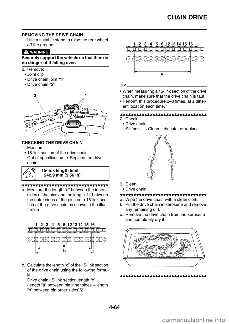
EAS1SL5191REMOVING THE DRIVE CHAIN
1. Use a suitable stand to raise the rear wheel
off the ground.
EWA13120
WARNING
Securely support the vehicle so that there is
no danger of it falling over.
2. Remove:
• Joint clip
• Drive chain joint “1”
• Drive chain “2”
EAS1SL5192CHECKING THE DRIVE CHAIN
1. Measure:
• 15-link section of the drive chain
Out of specification Replace the drive
chain.
▼▼▼▼▼▼▼▼▼▼▼▼▼▼▼▼▼▼▼▼▼▼▼▼▼▼▼▼▼▼▼▼
a. Measure the length “a” between the inner
sides of the pins and the length “b” between
the outer sides of the pins on a 15-link sec-
tion of the drive chain as shown in the illus-
tration.
b. Calculate the length “c” of the 15-link section
of the drive chain using the following formu-
la.
Drive chain 15-link section length “c” =
(length “a” between pin inner sides + length
“b” between pin outer sides)/2
TIP
• When measuring a 15-link section of the drive
chain, make sure that the drive chain is taut.
• Perform this procedure 2–3 times, at a differ-
ent location each time.
▲▲▲▲▲▲▲▲▲▲▲▲▲▲▲▲▲▲▲▲▲▲▲▲▲▲▲▲▲▲▲▲
2. Check:
•Drive chain
Stiffness Clean, lubricate, or replace.
3. Clean:
•Drive chain
▼▼▼▼▼▼▼▼▼▼▼▼▼▼▼▼▼▼▼▼▼▼▼▼▼▼▼▼▼▼▼▼
a. Wipe the drive chain with a clean cloth.
b. Put the drive chain in kerosene and remove
any remaining dirt.
c. Remove the drive chain from the kerosene
and completely dry it.
▲▲▲▲▲▲▲▲▲▲▲▲▲▲▲▲▲▲▲▲▲▲▲▲▲▲▲▲▲▲▲▲
15-link length limit
242.9 mm (9.56 in)
Page 191 of 360

CHAIN DRIVE
4-65
4. Check:
• Drive chain rollers “1”
Damage/wear Replace the drive chain.
• Drive chain side plates “2”
Damage/wear Replace the drive chain.
5. Lubricate:
•Drive chain
EAS1SL5193CHECKING THE DRIVE SPROCKET
1. Check:
• Drive sprocket
More than 1/4 tooth wear “a” Replace the
drive sprocket and the rear wheel sprocket
as a set.
Bent tooth Replace the drive sprocket
and the rear wheel sprocket as a set.
EAS1SL5194CHECKING THE REAR WHEEL SPROCKET
Refer to “CHECKING AND REPLACING THE
REAR WHEEL SPROCKET” on page 4-8.
EAS1SL5195INSTALLING THE DRIVE CHAIN
1. Install:
• Drive chain “1”
• Drive chain joint “2”
• Joint clip “3”
EWA
WARNING
When installing the joint clip, always keep
the direction as shown in the figure.2. Lubricate:
•Drive chain
3. Install:
• Drive sprocket
• Lock washer
• Drive sprocket nut
Refer to “ENGINE REMOVAL” on page 5-1.
ECA1DX1014
NOTICE
Never install a new drive chain onto worn
drive sprockets; this will dramatically short-
en the drive chain’s life.
4. Adjust:
• Drive chain slack
Refer to “ADJUSTING THE DRIVE CHAIN
SLACK” on page 3-27.
ECA13550
NOTICE
A drive chain that is too tight will overload
the engine and other vital parts, and one
that is too loose can skip and damage the
swingarm or cause an accident. Therefore,
keep the drive chain slack within the speci-
fied limits.
b. Correct
1. Drive chain roller
2. Drive sprocket
New
Drive sprocket nut
75 Nm (7.5 m·kgf, 54 ft·lbf)
Drive chain slack
50–60 mm (1.97–2.36 in)
New
T R..
Page 192 of 360

CHAIN DRIVE
4-66
Page 193 of 360

5
ENGINE
ENGINE REMOVAL......................................................................................... 5-1
REMOVING THE SILENCER ..................................................................... 5-6
REMOVING THE EXHAUST PIPE 2.......................................................... 5-6
REMOVING THE DRIVE SPROCKET ....................................................... 5-6
REMOVING THE ENGINE ......................................................................... 5-7
CHECKING THE SILENCER AND EXHAUST PIPE.................................. 5-7
CHANGING THE SILENCER FIBER ......................................................... 5-7
INSTALLING THE ENGINE........................................................................ 5-8
INSTALLING THE BRAKE PEDAL ............................................................ 5-9
INSTALLING THE DRIVE SPROCKET...................................................... 5-9
INSTALLING THE EXHAUST PIPE AND MUFFLER............................... 5-10
CAMSHAFT.................................................................................................... 5-11
REMOVING THE CAMSHAFT ................................................................. 5-13
CHECKING THE CAMSHAFT.................................................................. 5-14
CHECKING THE TIMING CHAIN AND CAMSHAFT SPROCKET .......... 5-15
CHECKING THE TIMING CHAIN TENSIONERS .................................... 5-15
CHECKING THE DECOMPRESSION SYSTEM...................................... 5-16
INSTALLING THE CAMSHAFTS ............................................................. 5-16
CYLINDER HEAD........................................................................................... 5-19
REMOVING THE CYLINDER HEAD........................................................ 5-21
CHECKING THE TIMING CHAIN GUIDE (INTAKE SIDE) ...................... 5-21
CHECKING THE CYLINDER HEAD ........................................................ 5-21
INSTALLING THE CYLINDER HEAD ...................................................... 5-22
VALVES AND VALVE SPRINGS................................................................... 5-24
REMOVING THE VALVES ....................................................................... 5-25
CHECKING THE VALVES AND VALVE GUIDES ................................... 5-26
CHECKING THE VALVE SEATS ............................................................. 5-27
CHECKING THE VALVE SPRINGS......................................................... 5-29
CHECKING THE VALVE LIFTERS .......................................................... 5-29
INSTALLING THE VALVES ..................................................................... 5-30
CYLINDER AND PISTON............................................................................... 5-32
REMOVING THE PISTON ....................................................................... 5-33
CHECKING THE CYLINDER AND PISTON ............................................ 5-33
CHECKING THE PISTON RINGS............................................................ 5-34
CHECKING THE PISTON PIN ................................................................. 5-35
INSTALLING THE PISTON AND CYLINDER .......................................... 5-35
Page 195 of 360

AC MAGNETO................................................................................................ 5-59
REMOVING THE AC MAGNETO............................................................. 5-60
CHECKING THE AC MAGNETO ............................................................. 5-60
CHECKING THE WOODRUFF KEY ........................................................ 5-60
INSTALLING THE AC MAGNETO ........................................................... 5-60
CRANKCASE................................................................................................. 5-62
DISASSEMBLING THE CRANKCASE..................................................... 5-65
REMOVING THE CRANKCASE BEARING ............................................. 5-65
CHECKING THE TIMING CHAIN, TIMING CHAIN GUIDE,
OIL STRAINER ........................................................................................ 5-65
CHECKING THE CRANKCASE ............................................................... 5-65
ASSEMBLING THE CRANKCASE........................................................... 5-66
CRANKSHAFT ASSEMBLY AND BALANCER SHAFT............................... 5-67
REMOVING THE BALANCER SHAFT..................................................... 5-68
REMOVING THE CRANKSHAFT ASSEMBLY ........................................ 5-68
CHECKING THE CRANKSHAFT ASSEMBLY......................................... 5-68
INSTALLING THE CRANKSHAFT ASSEMBLY....................................... 5-69
TRANSMISSION............................................................................................. 5-70
REMOVING THE TRANSMISSION ......................................................... 5-71
CHECKING THE SHIFT FORKS.............................................................. 5-71
CHECKING THE SHIFT DRUM ASSEMBLY ........................................... 5-72
CHECKING THE TRANSMISSION .......................................................... 5-72
INSTALLING THE TRANSMISSION ........................................................ 5-72
Page 199 of 360

ENGINE REMOVAL
5-4
Removing the engine
Order Part name Q’ty Remarks
Use a suitable stand to raise the front wheel
off the ground.
Seat Refer to “GENERAL CHASSIS” on page 4-1.
Side cover (left/right) Refer to “GENERAL CHASSIS” on page 4-1.
Air scoop (left / right) Refer to “GENERAL CHASSIS” on page 4-1.
Rear fender Refer to “GENERAL CHASSIS” on page 4-1.
Fuel tank Refer to “FUEL TANK” on page 7-1.
Exhaust pipe and silencer Refer to “ENGINE REMOVAL” on page 5-1.
Air filter case Refer to “THROTTLE BODY” on page 7-5.
Throttle body Refer to “THROTTLE BODY” on page 7-5.
Clutch cable Refer to “CLUTCH” on page 5-37.
Shift pedal Refer to “SHIFT SHAFT” on page 5-49.
1 Engine guard 1
2 Brake pedal 1
3Spring 1
4 Cylinder head breather hose 1
5 Drive sprocket cover 1
6 Drive chain guide 1
New
New
LS
M
8
8
7
6
11
45
New
1 10
3
2
Page 201 of 360

ENGINE REMOVAL
5-6
EAS1SL5198REMOVING THE SILENCER
1. Remove:
• Rear shock absorber assembly lower bolt
“1”
• Connecting arm bolt (frame side) “2”
• Silencer “3”
TIP
Move the rear shock absorber to the left side of
the chassis, and remove the silencer.
EAS1SL5199REMOVING THE EXHAUST PIPE 2
1. Remove:
• Exhaust pipe 2
TIP
Put the Exhaust pipe 2 into the state as shown
by moving this, and then remove it.
EAS1SL5200REMOVING THE DRIVE SPROCKET
1. Straighten the lock washer tab.
2. Remove:
• Nut (drive sprocket) “1”
• Lock washer “2”
TIP
Loosen the nut while applying the rear brake.
3. Remove:
• Drive sprocket “1”
• Drive chain “2”
TIP
Remove the drive sprocket together with the
drive chain.
1 2
3