check engine YAMAHA YZ450F 2015 User Guide
[x] Cancel search | Manufacturer: YAMAHA, Model Year: 2015, Model line: YZ450F, Model: YAMAHA YZ450F 2015Pages: 360, PDF Size: 10.82 MB
Page 58 of 360

TIGHTENING TORQUES
2-15
Air filter joint clamp bolt
M4 1 3.5 Nm (0.35 m·kgf, 2.5 ft·lbf)
Air filter case bolt M6 3 7 Nm (0.7 m·kgf, 5.1 ft·lbf)
Air filter bolt M6 1 2.0 Nm (0.20 m·kgf, 1.4 ft·lbf)
Air filter guide holder screw
M5 8 2.5 Nm (0.25 m·kgf, 1.8 ft·lbf)
Air filter case cap screw
M5 1 2.5 Nm (0.25 m·kgf, 1.8 ft·lbf)
Starter knob/Idle screw
M12 1 2.1 Nm (0.21 m·kgf, 1.5 ft·lbf)
Throttle cable nut (pull)
M10 1 7 Nm (0.7 m·kgf, 5.1 ft·lbf)
Throttle cable nut (return)
M10 1 7 Nm (0.7 m·kgf, 5.1 ft·lbf)
Clutch cable adjuster and locknut
M6 1 4.3 Nm (0.43 m·kgf, 3.1 ft·lbf)
Clutch cable locknut (engine side)
M8 1 7 Nm (0.7 m·kgf, 5.1 ft·lbf)
Exhaust pipe nut
M6 3 See TIP.
*2
Exhaust pipe protector screw
M6 4 10 Nm (1.0 m·kgf, 7.2 ft·lbf)
Exhaust pipe bracket bolt
M8 1 20 Nm (2.0 m·kgf, 14 ft·lbf)
Frame and silencer bolt (front) M8 1 30 Nm (3.0 m·kgf, 22 ft·lbf)
Frame and silencer bolt (rear) M8 1 30 Nm (3.0 m·kgf, 22 ft·lbf)
Exhaust pipe clamp bolt
M8 2 12 Nm (1.2 m·kgf, 8.7 ft·lbf)
Silencer body bolt
M5 6 8 Nm (0.8 m·kgf, 5.8 ft·lbf)
Oil nozzle bolt
M6 1 10 Nm (1.0 m·kgf, 7.2 ft·lbf)
Engine oil drain bolt
M10 1 20 Nm (2.0 m·kgf, 14 ft·lbf)
Crankcase bolt
M6 12 12 Nm (1.2 m·kgf, 8.7 ft·lbf)
Clutch cable holder bolt
M6 2 10 Nm (1.0 m·kgf, 7.2 ft·lbf)
Crankshaft end accessing screw
M36 1 10 Nm (1.0 m·kgf, 7.2 ft·lbf)
Timing mark accessing screw
M14 1 6 Nm (0.6 m·kgf, 4.3 ft·lbf)
Drive chain sprocket cover bolt
M6 2 7 Nm (0.7 m·kgf, 5.1 ft·lbf)
Crankcase bearing cover plate
screwM6 8 10 Nm (1.0 m·kgf, 7.2 ft·lbf)
Crankcase bearing cover plate
screw (crankshaft)M8 4 18 Nm (1.8 m·kgf, 13 ft·lbf) Crimp.
Clutch cover bolt
M6 7 10 Nm (1.0 m·kgf, 7.2 ft·lbf)
Oil level check window bolt
M6 1 10 Nm (1.0 m·kgf, 7.2 ft·lbf)
Left crankcase cover bolt
M6 7 10 Nm (1.0 m·kgf, 7.2 ft·lbf)
Right crankcase cover bolt
M6 11 10 Nm (1.0 m·kgf, 7.2 ft·lbf)
Oil filter element cover bolt
M6 2 10 Nm (1.0 m·kgf, 7.2 ft·lbf)
Oil level check window bolt
M6 1 10 Nm (1.0 m·kgf, 7.2 ft·lbf)
Kick shaft ratchet wheel guide bolt
M6 2 12 Nm (1.2 m·kgf, 8.7 ft·lbf)
Kick starter lever bolt
M8 1 33 Nm (3.3 m·kgf, 24 ft·lbf)
Kick starter lever boss screw
M6 1 7 Nm (0.7 m·kgf, 5.1 ft·lbf) ITEMThread
sizeQ’ty TIGHTENING TORQUES RemarksLT
LT
LT
LT
LT
LT
LT
Page 61 of 360
TIGHTENING TORQUES
2-18
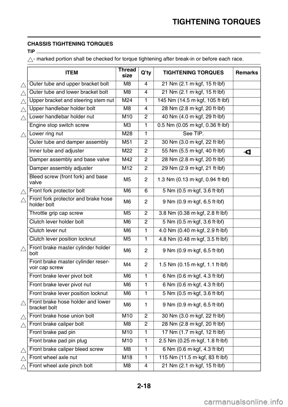
EAS1SL5059CHASSIS TIGHTENING TORQUES
TIP
- marked portion shall be checked for torque tightening after break-in or before each race.
ITEMThread
sizeQ’ty TIGHTENING TORQUES Remarks
Outer tube and upper bracket bolt M8 4 21 Nm (2.1 m·kgf, 15 ft·lbf)
Outer tube and lower bracket bolt M8 4 21 Nm (2.1 m·kgf, 15 ft·lbf)
Upper bracket and steering stem nut M24 1 145 Nm (14.5 m·kgf, 105 ft·lbf)
Upper handlebar holder bolt M8 4 28 Nm (2.8 m·kgf, 20 ft·lbf)
Lower handlebar holder nut M10 2 40 Nm (4.0 m·kgf, 29 ft·lbf)
Engine stop switch screw M3 1 0.5 Nm (0.05 m·kgf, 0.36 ft·lbf)
Lower ring nut M28 1 See TIP.
Outer tube and damper assembly M51 2 30 Nm (3.0 m·kgf, 22 ft·lbf)
Inner tube and adjuster M22 2 55 Nm (5.5 m·kgf, 40 ft·lbf)
Damper assembly and base valve M42 2 28 Nm (2.8 m·kgf, 20 ft·lbf)
Damper assembly adjuster M12 2 29 Nm (2.9 m·kgf, 21 ft·lbf)
Bleed screw (front fork) and base
valveM5 2 1.3 Nm (0.13 m·kgf, 0.94 ft·lbf)
Front fork protector bolt M6 6 5 Nm (0.5 m·kgf, 3.6 ft·lbf)
Front fork protector and brake hose
holder boltM6 2 9 Nm (0.9 m·kgf, 6.5 ft·lbf)
Throttle grip cap screw M5 2 3.8 Nm (0.38 m·kgf, 2.8 ft·lbf)
Clutch lever holder bolt M6 2 5 Nm (0.5 m·kgf, 3.6 ft·lbf)
Clutch lever nut M6 1 4.0 Nm (0.40 m·kgf, 2.9 ft·lbf)
Clutch lever position locknut M5 1
4.8 Nm (0.48 m·kgf, 3.5 ft·lbf)
Front brake master cylinder holder
boltM6 2 9 Nm (0.9 m·kgf, 6.5 ft·lbf)
Front brake master cylinder reser-
voir cap screwM4 2 1.5 Nm (0.15 m·kgf, 1.1 ft·lbf)
Front brake lever pivot bolt M6 1 6 Nm (0.6 m·kgf, 4.3 ft·lbf)
Front brake lever pivot nut M6 1 6 Nm (0.6 m·kgf, 4.3 ft·lbf)
Front brake lever position locknut M6 1 5 Nm (0.5 m·kgf, 3.6 ft·lbf)
Front brake hose holder and lower
bracket boltM6 1 9 Nm (0.9 m·kgf, 6.5 ft·lbf)
Front brake hose union bolt M10 2 30 Nm (3.0 m·kgf, 22 ft·lbf)
Front brake caliper bolt M8 2 28 Nm (2.8 m·kgf, 20 ft·lbf)
Front brake pad pin M10 1 17 Nm (1.7 m·kgf, 12 ft·lbf)
Front brake pad pin plug M10 1 2.5 Nm (0.25 m·kgf, 1.8 ft·lbf)
Front brake caliper bleed screw M8 1 6 Nm (0.6 m·kgf, 4.3 ft·lbf)
Front wheel axle nut M18 1 115 Nm (11.5 m·kgf, 83 ft·lbf)
Front wheel axle pinch bolt M8 4 21 Nm (2.1 m·kgf, 15 ft·lbf)
LT
Page 87 of 360

3
PERIODIC CHECKS AND ADJUSTMENTS
MAINTENANCE INTERVALS.......................................................................... 3-1
MAINTENANCE INTERVALS .................................................................... 3-1
PRE-OPERATION INSPECTION AND MAINTENANCE................................. 3-7
GENERAL INSPECTION AND MAINTENANCE........................................ 3-7
ENGINE............................................................................................................ 3-8
CHECKING THE COOLANT LEVEL .......................................................... 3-8
CHECKING THE COOLING SYSTEM ....................................................... 3-8
CHANGING THE COOLANT...................................................................... 3-8
CHECKING THE RADIATOR CAP ............................................................ 3-9
CHECKING THE RADIATOR CAP OPENING PRESSURE ...................... 3-9
CHECKING THE COOLANT CIRCULATORY SYSTEM FOR LEAKS .... 3-10
ADJUSTING THE CLUTCH LEVER POSITION ...................................... 3-10
ADJUSTING THE CLUTCH LEVER FREE PLAY .................................... 3-10
ADJUSTING THE THROTTLE GRIP FREE PLAY .................................. 3-11
LUBRICATING THE THROTTLE CABLE ................................................ 3-12
CLEANING THE AIR FILTER ELEMENT................................................. 3-12
CHECKING THE THROTTLE BODY JOINT ............................................ 3-13
CHECKING THE BREATHER HOSES .................................................... 3-13
CHECKING THE EXHAUST SYSTEM..................................................... 3-13
CHECKING THE FUEL LINE ................................................................... 3-14
CHECKING THE ENGINE OIL LEVEL..................................................... 3-14
CHANGING THE ENGINE OIL ................................................................ 3-15
ADJUSTING THE ENGINE IDLING SPEED ............................................ 3-16
ADJUSTING THE VALVE CLEARANCE ................................................. 3-17
CHASSIS........................................................................................................ 3-21
BLEEDING THE BRAKE SYSTEM .......................................................... 3-21
CHECKING THE BRAKE HOSE .............................................................. 3-22
ADJUSTING THE FRONT BRAKE .......................................................... 3-22
ADJUSTING THE REAR BRAKE ............................................................. 3-23
CHECKING THE FRONT BRAKE PADS ................................................. 3-23
CHECKING THE REAR BRAKE PADS ................................................... 3-25
CHECKING THE REAR BRAKE PAD INSULATOR ................................ 3-26
CHECKING THE BRAKE FLUID LEVEL.................................................. 3-26
ADJUSTING THE DRIVE CHAIN SLACK ................................................ 3-27
CHECKING THE FRONT FORK LEGS ................................................... 3-28
CHECKING THE FRONT FORK PROTECTOR GUIDE .......................... 3-28
CLEANING THE FRONT FORK OIL SEAL AND DUST SEAL ................ 3-28
AIR BLEEDING FROM FRONT FORK .................................................... 3-28
ADJUSTING THE FRONT FORK LEGS .................................................. 3-29
CHECKING THE SWINGARM OPERATION ........................................... 3-30
CHECKING THE REAR SUSPENSION ................................................... 3-30
ADJUSTING THE REAR SHOCK ABSORBER ASSEMBLY ................... 3-30
CHECKING THE TIRES ........................................................................... 3-32
CHECKING AND TIGHTENING THE SPOKES ....................................... 3-32
CHECKING THE WHEELS ...................................................................... 3-33
Page 89 of 360
MAINTENANCE INTERVALS
3-1
EAS1SL5066
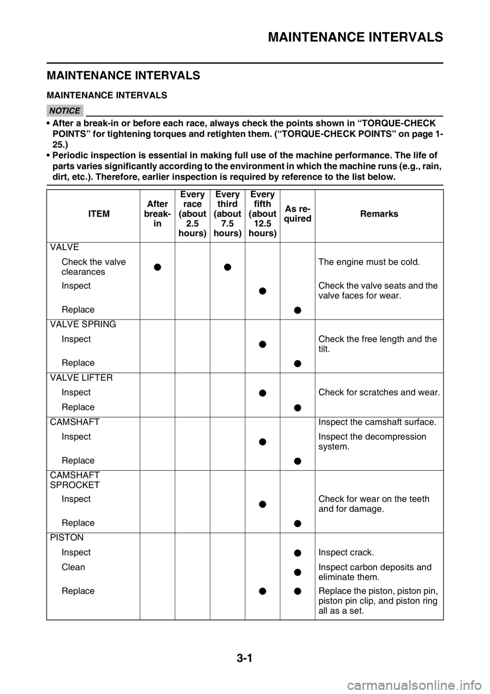
MAINTENANCE INTERVALS
EAS1SL5067MAINTENANCE INTERVALSECA@
NOTICE
• After a break-in or before each race, always check the points shown in “TORQUE-CHECK
POINTS” for tightening torques and retighten them. (“TORQUE-CHECK POINTS” on page 1-
25.)
• Periodic inspection is essential in making full use of the machine performance. The life of
parts varies significantly according to the environment in which the machine runs (e.g., rain,
dirt, etc.). Therefore, earlier inspection is required by reference to the list below.
ITEMAfter
break-
inEvery
race
(about
2.5
hours)Every
third
(about
7.5
hours)Every
fifth
(about
12.5
hours)As re-
quiredRemarks
VALVE
Check the valve
clearancesThe engine must be cold.
Inspect Check the valve seats and the
valve faces for wear.
Replace
VALVE SPRING
Inspect Check the free length and the
tilt.
Replace
VALVE LIFTER
Inspect Check for scratches and wear.
Replace
CAMSHAFT Inspect the camshaft surface.
Inspect Inspect the decompression
system.
Replace
CAMSHAFT
SPROCKET
Inspect Check for wear on the teeth
and for damage.
Replace
PISTON
Inspect Inspect crack.
Clean Inspect carbon deposits and
eliminate them.
Replace Replace the piston, piston pin,
piston pin clip, and piston ring
all as a set.
Page 90 of 360
MAINTENANCE INTERVALS
3-2
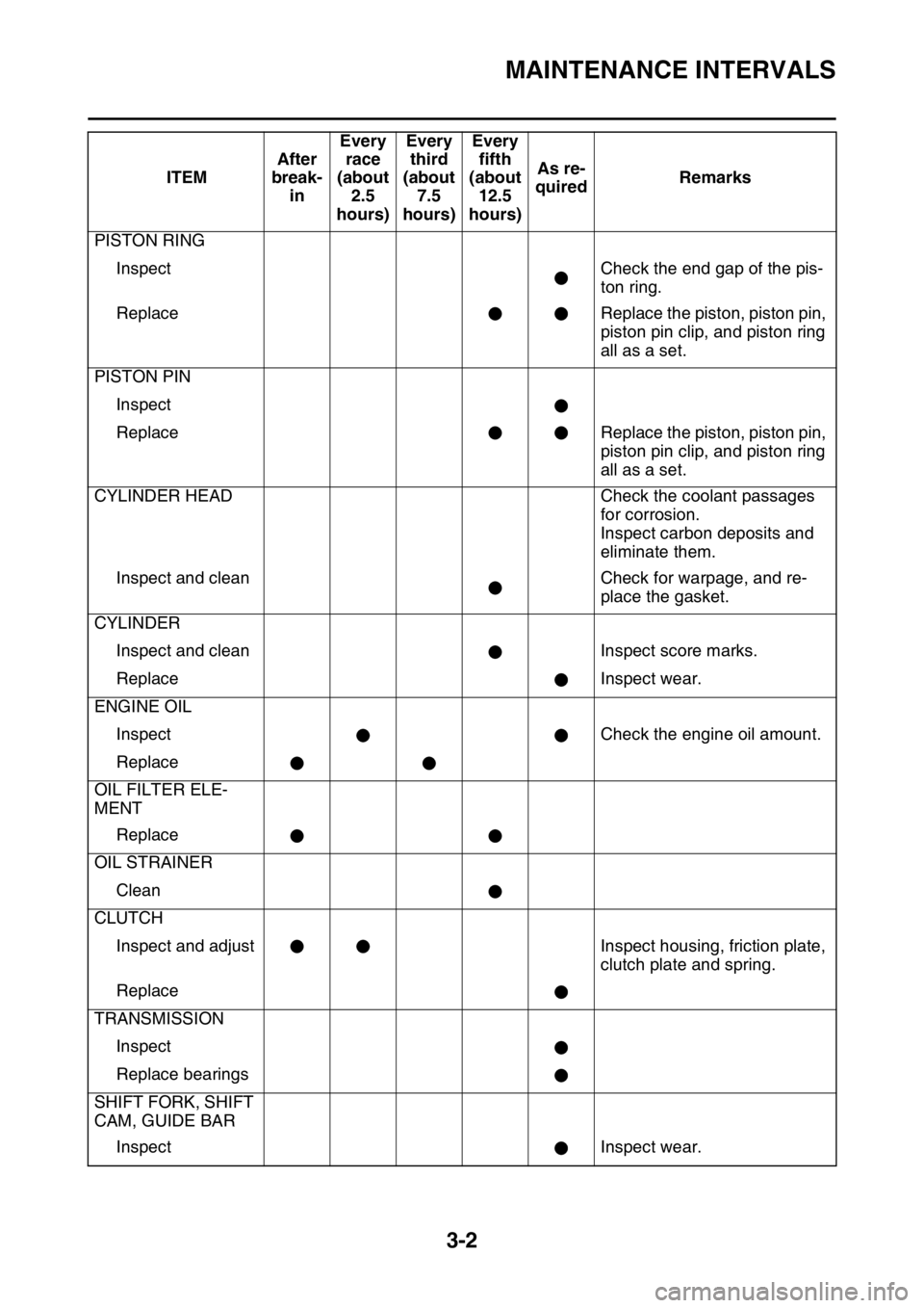
PISTON RING
Inspect Check the end gap of the pis-
ton ring.
Replace Replace the piston, piston pin,
piston pin clip, and piston ring
all as a set.
PISTON PIN
Inspect
Replace Replace the piston, piston pin,
piston pin clip, and piston ring
all as a set.
CYLINDER HEAD Check the coolant passages
for corrosion.
Inspect carbon deposits and
eliminate them.
Inspect and clean Check for warpage, and re-
place the gasket.
CYLINDER
Inspect and clean Inspect score marks.
Replace Inspect wear.
ENGINE OIL
Inspect Check the engine oil amount.
Replace
OIL FILTER ELE-
MENT
Replace
OIL STRAINER
Clean
CLUTCH
Inspect and adjust Inspect housing, friction plate,
clutch plate and spring.
Replace
TRANSMISSION
Inspect
Replace bearings
SHIFT FORK, SHIFT
CAM, GUIDE BAR
Inspect Inspect wear.ITEMAfter
break-
inEvery
race
(about
2.5
hours)Every
third
(about
7.5
hours)Every
fifth
(about
12.5
hours)As re-
quiredRemarks
Page 91 of 360
MAINTENANCE INTERVALS
3-3
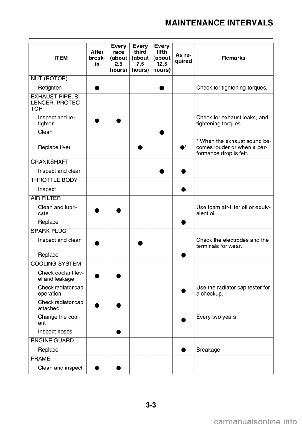
NUT (ROTOR)
Retighten Check for tightening torques.
EXHAUST PIPE, SI-
LENCER, PROTEC-
TOR
Inspect and re-
tightenCheck for exhaust leaks, and
tightening torques.
Clean
Replace fiver ** When the exhaust sound be-
comes louder or when a per-
formance drop is felt.
CRANKSHAFT
Inspect and clean
THROTTLE BODY
Inspect
AIR FILTER
Clean and lubri-
cateUse foam air-filter oil or equiv-
alent oil.
Replace
SPARK PLUG
Inspect and clean Check the electrodes and the
terminals for wear.
Replace
COOLING SYSTEM
Check coolant lev-
el and leakage
Check radiator cap
operationUse the radiator cap tester for
a checkup.
Check radiator cap
attached
Change the cool-
antEvery two years
Inspect hoses
ENGINE GUARD
Replace Breakage
FRAME
Clean and inspectITEMAfter
break-
inEvery
race
(about
2.5
hours)Every
third
(about
7.5
hours)Every
fifth
(about
12.5
hours)As re-
quiredRemarks
Page 95 of 360

PRE-OPERATION INSPECTION AND MAINTENANCE
3-7
EAS1SL5068
PRE-OPERATION INSPECTION AND MAINTENANCE
Before riding for break-in operation, practice or a race, make sure the machine is in good operating
condition.
Before using this machine, check the following points.
EAS1SL5069GENERAL INSPECTION AND MAINTENANCE
TIP
Perform usual maintenance enough so that, in the race course, a confirmation of that and simple set-
ting adjustments may only be left, in order to get enough time to use effectively.ITEM inspect Page
CoolantCheck that coolant is filled up to the radiator cap.
Check the cooling system for leakage.3-8 – 10
FuelCheck that a fresh gasoline is filled in the fuel tank.
Check the fuel line for leakage.1-22
Engine oilCheck that the oil level is correct. Check the crank-
case and oil line for leakage.3-14 – 16
Gear shifter and clutchCheck that gears can be shifted correctly in order and
that the clutch operates smoothly.3-10 – 11
Throttle grip/HousingCheck that the throttle grip operation and free play
are correctly adjusted. Lubricate the throttle grip and
housing, if necessary.3-11 – 12
BrakesCheck the play of front brake and effect of front and
rear brake.3-21 – 27
Drive chainCheck drive chain slack and alignment. Check that
the drive chain is lubricated properly.3-27
4-64 – 65
WheelsCheck for excessive wear and tire pressure. Check
for loose spokes and have no excessive play.3-32 – 33
SteeringCheck that the handlebar can be turned smoothly and
have no excessive play.3-33 – 34
Front forks and rear
shock absorberCheck that they operate smoothly and there is no oil
leakage.3-28 – 32
Cables (wires)Check that the clutch and throttle cables move
smoothly. Check that they are not caught when the
handlebars are turned or when the front forks travel
up and down.—
Exhaust pipeCheck that the exhaust pipe is tightly mounted and
has no cracks.3-13 – 14
Rear wheel sprocketCheck that the rear wheel sprocket tightening bolt is
not loose.4-8 – 9
Lubrication Check for smooth operation. Lubricate if necessary. 3-12 , 3-34
Bolts and nutsCheck the chassis and engine for loose bolts and
nuts.1-25 – 26
Lead connectorsCheck that the AC magneto, ECU and ignition coil are
connected tightly.1-12 – 14
SettingsIs the machine set suitably for the condition of the rac-
ing course and weather or by taking into account the
results of test runs before racing? Are inspection and
maintenance completely done?10-1 – 8
Page 96 of 360
ENGINE
3-8
EAS1SL5070
ENGINE
EAS1SL5071CHECKING THE COOLANT LEVELEWA1DX1003
WARNING
If coolant seems hot, do not remove the ra-
diator cap.
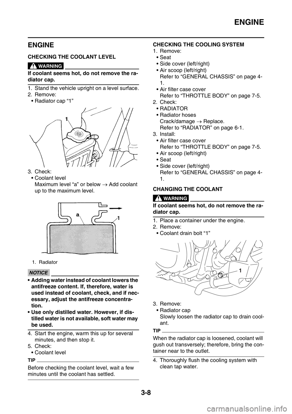
1. Stand the vehicle upright on a level surface.
2. Remove:
• Radiator cap “1”
3. Check:
• Coolant level
Maximum level “a” or below Add coolant
up to the maximum level.
ECA1DX1004
NOTICE
• Adding water instead of coolant lowers the
antifreeze content. If, therefore, water is
used instead of coolant, check, and if nec-
essary, adjust the antifreeze concentra-
tion.
• Use only distilled water. However, if dis-
tilled water is not available, soft water may
be used.
4. Start the engine, warm this up for several
minutes, and then stop it.
5. Check:
• Coolant level
TIP
Before checking the coolant level, wait a few
minutes until the coolant has settled.
EAS1SL5072CHECKING THE COOLING SYSTEM
1. Remove:
• Seat
• Side cover (left/right)
• Air scoop (left/right)
Refer to “GENERAL CHASSIS” on page 4-
1.
• Air filter case cover
Refer to “THROTTLE BODY” on page 7-5.
2. Check:
•RADIATOR
• Radiator hoses
Crack/damage Replace.
Refer to “RADIATOR” on page 6-1.
3. Install:
• Air filter case cover
Refer to “THROTTLE BODY” on page 7-5.
• Air scoop (left/right)
• Seat
• Side cover (left/right)
Refer to “GENERAL CHASSIS” on page 4-
1.
EAS1SL5073CHANGING THE COOLANTEWA1DX1004
WARNING
If coolant seems hot, do not remove the ra-
diator cap.
1. Place a container under the engine.
2. Remove:
• Coolant drain bolt “1”
3. Remove:
• Radiator cap
Slowly loosen the radiator cap to drain cool-
ant.
TIP
When the radiator cap is loosened, coolant will
gush out transversely; therefore, bring the con-
tainer near to the outlet.
4. Thoroughly flush the cooling system with
clean tap water.
1. Radiator
1
Page 97 of 360
ENGINE
3-9
5. Install:
• Copper washers
• Coolant drain bolt
6. Pour coolant.
EWA13040
WARNING
• If coolant splashes in your eyes, thorough-
ly wash them with water and consult a
doctor.
• If coolant splashes on your clothes, quick-
ly wash it away with water and then with
soap and water.
• If coolant is swallowed, induce vomiting
and get immediate medical attention.
ECA13480
NOTICE
• Adding water instead of coolant lowers the
antifreeze content of the coolant. If water
is used instead of coolant check, and if
necessary, correct the antifreeze concen-
tration of the coolant.
• Use only distilled water. However, if dis-
tilled water is not available, soft water may
be used.
• If coolant comes into contact with painted
surfaces, immediately wash them with wa-
ter.
• Do not mix different types of antifreeze.
7. Install:
• Radiator cap
8. Start the engine, warm this up for several
minutes, stop it, and then wait for it to cool
down.
9. Check:
• Coolant level
Refer to “CHECKING THE COOLANT LEV-
EL” on page 3-8.
EAS1SL5074CHECKING THE RADIATOR CAP
1. Check:
• Seal (radiator cap) “1”• Valve and valve seat “2”
Crack/damage Replace.
Exist fur deposits Clean or replace.
EAS1SL5075CHECKING THE RADIATOR CAP OPENING
PRESSURE
1. Check:
• Radiator cap opening pressure
▼▼▼▼▼▼▼▼▼▼▼▼▼▼▼▼▼▼▼▼▼▼▼▼▼▼▼▼▼▼▼▼
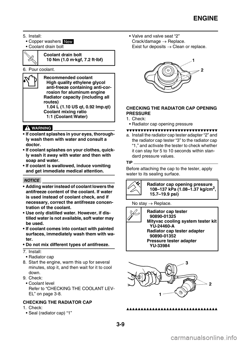
a. Install the radiator cap tester adapter “2” and
the radiator cap tester “3” to the radiator cap
“1,” and activate the tester to check whether
it can stay for 5 to 10 seconds within stan-
dard pressure values.
TIP
Before attaching the cap to the tester, apply
water to its sealing surface.
No stay Replace.
▲▲▲▲▲▲▲▲▲▲▲▲▲▲▲▲▲▲▲▲▲▲▲▲▲▲▲▲▲▲▲▲
Coolant drain bolt
10 Nm (1.0 m·kgf, 7.2 ft·lbf)
Recommended coolant
High quality ethylene glycol
anti-freeze containing anti-cor-
rosion for aluminum engine
Radiator capacity (including all
routes)
1.04 L (1.10 US qt, 0.92 Imp.qt)
Coolant mixing ratio
1:1 (Coolant:Water)
New
T R..
Radiator cap opening pressure
108–137 kPa (1.08–1.37 kg/cm2,
15.7–19.9 psi)
Radiator cap tester
90890-01325
Mityvac cooling system tester kit
YU-24460-A
Radiator cap tester adapter
90890-01352
Pressure tester adapter
YU-33984
Page 98 of 360
ENGINE
3-10
EAS1SL5076CHECKING THE COOLANT CIRCULATORY
SYSTEM FOR LEAKS
1. Check:
• Coolant level
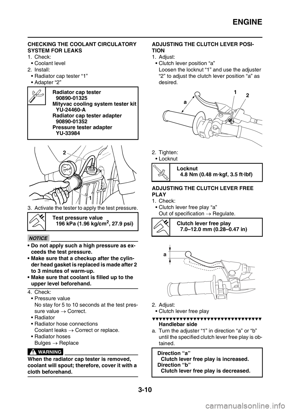
2. Install:
• Radiator cap tester “1”
• Adapter “2”
3. Activate the tester to apply the test pressure.
ECA@
NOTICE
• Do not apply such a high pressure as ex-
ceeds the test pressure.
• Make sure that a checkup after the cylin-
der head gasket is replaced is made after 2
to 3 minutes of warm-up.
• Make sure that coolant is filled up to the
upper level beforehand.
4. Check:
• Pressure value
No stay for 5 to 10 seconds at the test pres-
sure value Correct.
• Radiator
• Radiator hose connections
Coolant leaks Correct or replace.
• Radiator hoses
Bulges Replace
EWA@
WARNING
When the radiator cap tester is removed,
coolant will spout; therefore, cover it with a
cloth beforehand.
EAS1SL5077ADJUSTING THE CLUTCH LEVER POSI-
TION
1. Adjust:
• Clutch lever position “a”
Loosen the locknut “1” and use the adjuster
“2” to adjust the clutch lever position “a” as
desired.
2. Tighten:
• Locknut
EAS1SL5078ADJUSTING THE CLUTCH LEVER FREE
PLAY
1. Check:
• Clutch lever free play “a”
Out of specification Regulate.
2. Adjust:
• Clutch lever free play
▼▼▼▼▼▼▼▼▼▼▼▼▼▼▼▼▼▼▼▼▼▼▼▼▼▼▼▼▼▼▼▼
Handlebar side
a. Turn the adjuster “1” in direction “a” or “b”
until the specified clutch lever free play is ob-
tained. Radiator cap tester
90890-01325
Mityvac cooling system tester kit
YU-24460-A
Radiator cap tester adapter
90890-01352
Pressure tester adapter
YU-33984
Test pressure value
196 kPa (1.96 kg/cm
2, 27.9 psi)
Locknut
4.8 Nm (0.48 m·kgf, 3.5 ft·lbf)
Clutch lever free play
7.0–12.0 mm (0.28–0.47 in)
Direction “a”
Clutch lever free play is increased.
Direction “b”
Clutch lever free play is decreased.
1
2
a
T R..