oil level YAMAHA YZ450F 2016 User Guide
[x] Cancel search | Manufacturer: YAMAHA, Model Year: 2016, Model line: YZ450F, Model: YAMAHA YZ450F 2016Pages: 362, PDF Size: 10.49 MB
Page 142 of 362
FRONT BRAKE
4-18
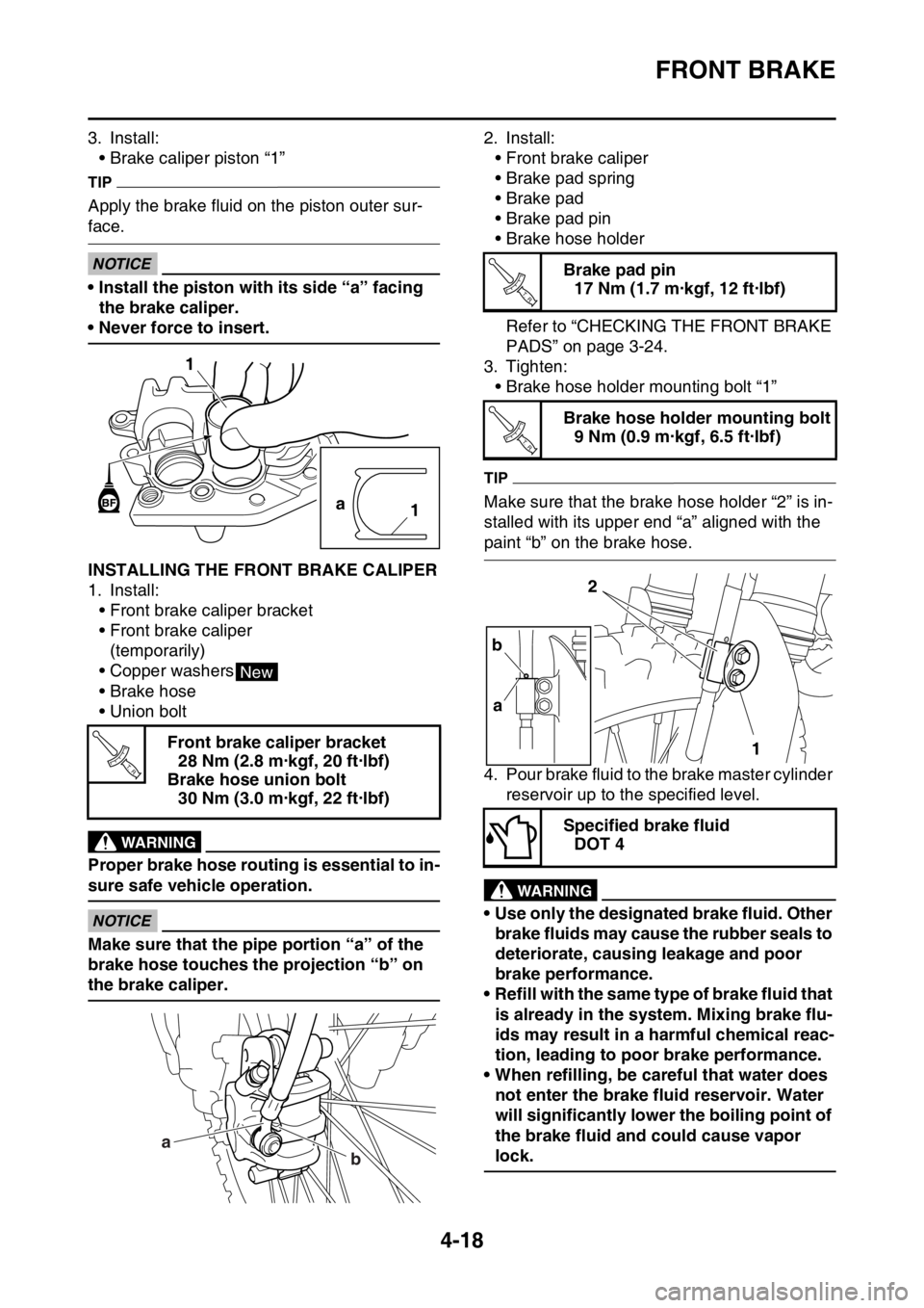
3. Install:
• Brake caliper piston “1”
TIP
Apply the brake fluid on the piston outer sur-
face.
ECA
NOTICE
• Install the piston with its side “a” facing
the brake caliper.
• Never force to insert.
EASB111142INSTALLING THE FRONT BRAKE CALIPER
1. Install:
• Front brake caliper bracket
• Front brake caliper
(temporarily)
• Copper washers
• Brake hose
• Union bolt
EWA
WARNING
Proper brake hose routing is essential to in-
sure safe vehicle operation.
ECA
NOTICE
Make sure that the pipe portion “a” of the
brake hose touches the projection “b” on
the brake caliper.2. Install:
• Front brake caliper
• Brake pad spring
• Brake pad
• Brake pad pin
• Brake hose holder
Refer to “CHECKING THE FRONT BRAKE
PADS” on page 3-24.
3. Tighten:
• Brake hose holder mounting bolt “1”
TIP
Make sure that the brake hose holder “2” is in-
stalled with its upper end “a” aligned with the
paint “b” on the brake hose.
4. Pour brake fluid to the brake master cylinder
reservoir up to the specified level.
EWA
WARNING
• Use only the designated brake fluid. Other
brake fluids may cause the rubber seals to
deteriorate, causing leakage and poor
brake performance.
• Refill with the same type of brake fluid that
is already in the system. Mixing brake flu-
ids may result in a harmful chemical reac-
tion, leading to poor brake performance.
• When refilling, be careful that water does
not enter the brake fluid reservoir. Water
will significantly lower the boiling point of
the brake fluid and could cause vapor
lock.
ECA
Front brake caliper bracket
28 Nm (2.8 m·kgf, 20 ft·lbf)
Brake hose union bolt
30 Nm (3.0 m·kgf, 22 ft·lbf)
1
a
1
New
T R..
a
b
Brake pad pin
17 Nm (1.7 m·kgf, 12 ft·lbf)
Brake hose holder mounting bolt
9 Nm (0.9 m·kgf, 6.5 ft·lbf)
Specified brake fluid
DOT 4
T R..
T R..
2
1 b
a
Page 145 of 362
FRONT BRAKE
4-21
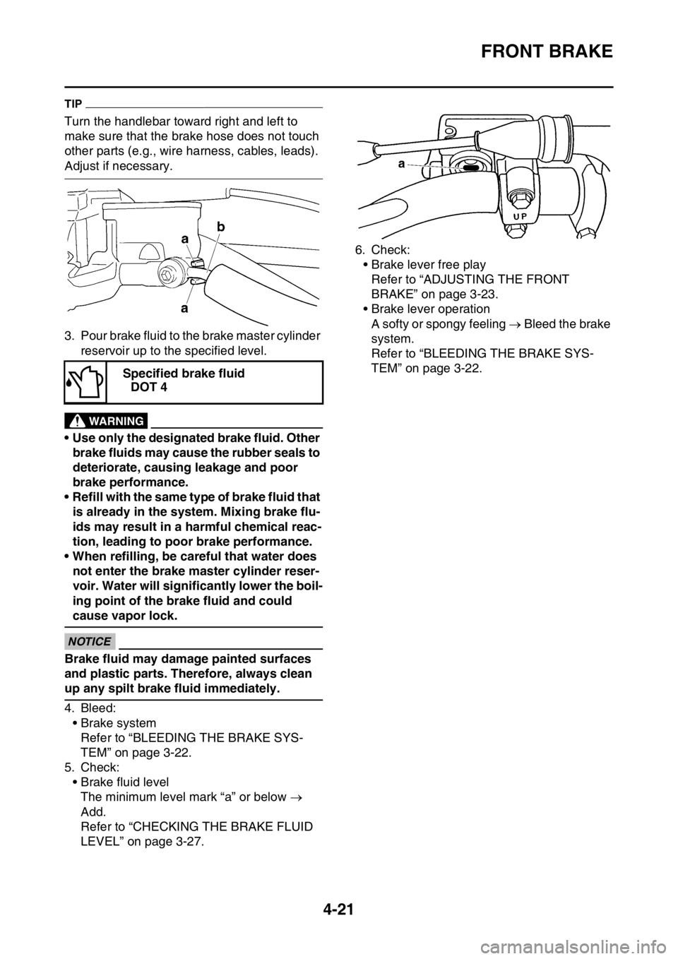
TIP
Turn the handlebar toward right and left to
make sure that the brake hose does not touch
other parts (e.g., wire harness, cables, leads).
Adjust if necessary.
3. Pour brake fluid to the brake master cylinder
reservoir up to the specified level.
EWA13540
WARNING
• Use only the designated brake fluid. Other
brake fluids may cause the rubber seals to
deteriorate, causing leakage and poor
brake performance.
• Refill with the same type of brake fluid that
is already in the system. Mixing brake flu-
ids may result in a harmful chemical reac-
tion, leading to poor brake performance.
• When refilling, be careful that water does
not enter the brake master cylinder reser-
voir. Water will significantly lower the boil-
ing point of the brake fluid and could
cause vapor lock.
ECA13540
NOTICE
Brake fluid may damage painted surfaces
and plastic parts. Therefore, always clean
up any spilt brake fluid immediately.
4. Bleed:
• Brake system
Refer to “BLEEDING THE BRAKE SYS-
TEM” on page 3-22.
5. Check:
• Brake fluid level
The minimum level mark “a” or below
Add.
Refer to “CHECKING THE BRAKE FLUID
LEVEL” on page 3-27.6. Check:
• Brake lever free play
Refer to “ADJUSTING THE FRONT
BRAKE” on page 3-23.
• Brake lever operation
A softy or spongy feeling Bleed the brake
system.
Refer to “BLEEDING THE BRAKE SYS-
TEM” on page 3-22.
Specified brake fluid
DOT 4
Page 153 of 362
REAR BRAKE
4-29
WARNING
• Use only the designated brake fluid. Other
brake fluids may cause the rubber seals to
deteriorate, causing leakage and poor
brake performance.
• Refill with the same type of brake fluid that
is already in the system. Mixing brake flu-
ids may result in a harmful chemical reac-
tion, leading to poor brake performance.
• When refilling, be careful that water does
not enter the brake fluid reservoir. Water
will significantly lower the boiling point of
the brake fluid and could cause vapor
lock.
ECA
NOTICE
Brake fluid may damage painted surfaces
and plastic parts. Therefore, always clean
up any spilt brake fluid immediately.
5. Bleed:
• Brake system
Refer to “BLEEDING THE BRAKE SYS-
TEM” on page 3-22.
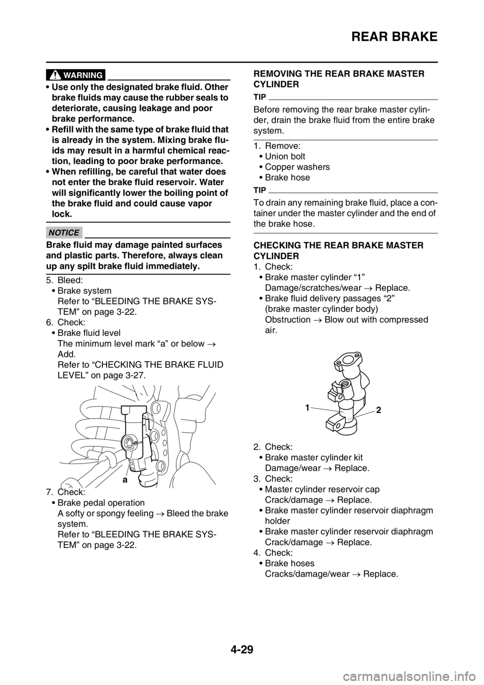
6. Check:
• Brake fluid level
The minimum level mark “a” or below
Add.
Refer to “CHECKING THE BRAKE FLUID
LEVEL” on page 3-27.
7. Check:
• Brake pedal operation
A softy or spongy feeling Bleed the brake
system.
Refer to “BLEEDING THE BRAKE SYS-
TEM” on page 3-22.
EASB111156REMOVING THE REAR BRAKE MASTER
CYLINDER
TIP
Before removing the rear brake master cylin-
der, drain the brake fluid from the entire brake
system.
1. Remove:
• Union bolt
• Copper washers
• Brake hose
TIP
To drain any remaining brake fluid, place a con-
tainer under the master cylinder and the end of
the brake hose.
EASB111157CHECKING THE REAR BRAKE MASTER
CYLINDER
1. Check:
• Brake master cylinder “1”
Damage/scratches/wear Replace.
• Brake fluid delivery passages “2”
(brake master cylinder body)
Obstruction Blow out with compressed
air.
2. Check:
• Brake master cylinder kit
Damage/wear Replace.
3. Check:
• Master cylinder reservoir cap
Crack/damage Replace.
• Brake master cylinder reservoir diaphragm
holder
• Brake master cylinder reservoir diaphragm
Crack/damage Replace.
4. Check:
• Brake hoses
Cracks/damage/wear Replace.
a
1
2
Page 155 of 362
REAR BRAKE
4-31
2. Pour brake fluid to the brake fluid reservoir
up to the specified level.
EWA
WARNING
• Use only the designated brake fluid. Other
brake fluids may cause the rubber seals to
deteriorate, causing leakage and poor
brake performance.
• Refill with the same type of brake fluid that
is already in the system. Mixing brake flu-
ids may result in a harmful chemical reac-
tion, leading to poor brake performance.
• When refilling, be careful that water does
not enter the brake fluid reservoir. Water
will significantly lower the boiling point of
the brake fluid and could cause vapor
lock.
ECA
NOTICE
Brake fluid may damage painted surfaces
and plastic parts. Therefore, always clean
up any spilt brake fluid immediately.
3. Bleed:
• Brake system
Refer to “BLEEDING THE BRAKE SYS-
TEM” on page 3-22.
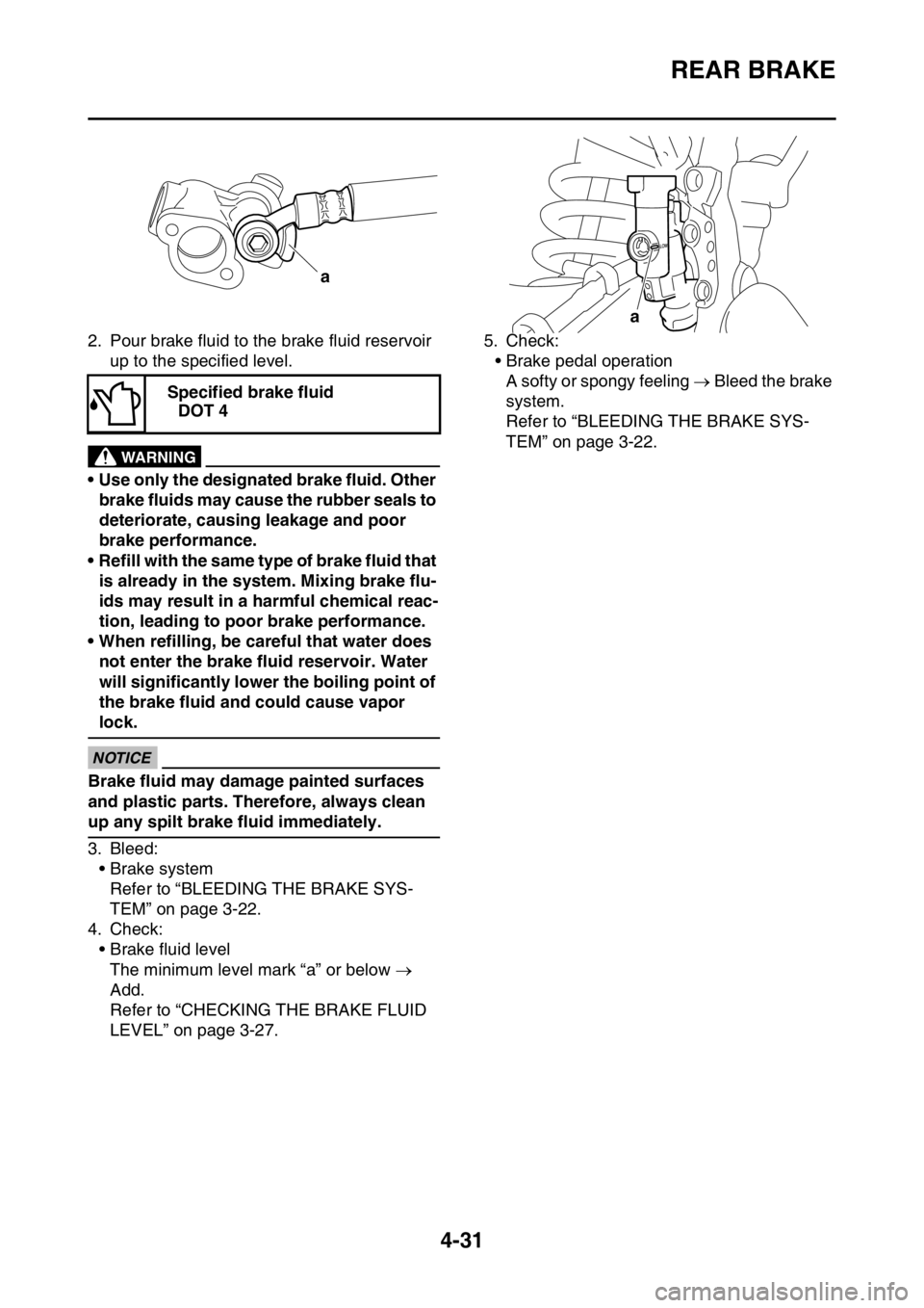
4. Check:
• Brake fluid level
The minimum level mark “a” or below
Add.
Refer to “CHECKING THE BRAKE FLUID
LEVEL” on page 3-27.5. Check:
• Brake pedal operation
A softy or spongy feeling Bleed the brake
system.
Refer to “BLEEDING THE BRAKE SYS-
TEM” on page 3-22. Specified brake fluid
DOT 4
a
a
Page 166 of 362

FRONT FORK
4-42
5. Check:
• Base valve “1”
Wear/damage Replace.
Contamination Clean.
• O-rings “2”
Wear/damage Replace.
• Base valve bushing “3”
Wear/damage Replace.
• Spring “4”
Damage/fatigue Replace the base valve.
• Air bleed screw “5”
Wear/damage Replace.
6. Check:
• Contacting surface “a”
Wear/damage Replace.
7. Check:
• Adjuster “1”
• O-rings “2”
Wear/damage Replace.EASB111168ASSEMBLING THE FRONT FORK LEGSEWA13660
WARNING
• Make sure the oil levels in both front fork
legs are equal.
• Uneven oil levels can result in poor han-
dling and a loss of stability.
TIP
• When assembling the front fork leg, be sure to
replace the following parts:
• Inner tube bushing
• Outer tube bushing
• Oil seals
• Copper washers
• Before assembling the front fork leg, make
sure that all of the components are clean.
1. Stretch the damper assembly fully.
2. Fill:
• Damper assembly
ECA14210
NOTICE
• Be sure to use the recommended oil. Other
oils may have an adverse effect on front
fork performance.
• When disassembling and assembling the
front fork leg, take care not to allow any
foreign material to enter the front fork.
3. After filling, pump the damper assembly “1”
slowly up and down (about 200 mm (7.9 in)
stroke) several times to bleed the damper
assembly of air.
TIP
Avoid excessive full stroke. A stroke of 200 mm
(7.9 in) or more will cause air to enter. In this
case, repeat the steps 1 to 3.
21
New
New
New
2
21 543
a
New
Recommended oil
Suspension oil S1
Standard oil amount
204 cm
3 (6.90 US oz, 7.20
Imp.oz)
New
1
2
Page 167 of 362

FRONT FORK
4-43
4. Measure:
• Oil level (left and right) “a”
Out of specification Regulate.
5. Tighten:
• Locknut “1”
TIP
Fully finger tighten the locknut onto the damper
assembly.6. Loosen:
• Compression damping force adjuster “1”
TIP
• Before loosening the damping force adjuster,
record the setting position.
• Unless the damping force adjuster is fully
loosened, correct damping characteristic can-
not be obtained after installation.
7. Install:
• Base valve “1”
(to the damper assembly “2”)
TIP
First bring the damper rod pressure to a maxi-
mum. Then install the base valve while releas-
ing the damper rod pressure.
8. Check:
• Damper assembly
Not fully stretched Repeat the steps 1 to
7. Standard oil level
145–148 mm (5.71–5.83 in)
From top of fully stretched
damper assembly.
1
a1
1
2
Page 278 of 362
WATER PUMP
6-5
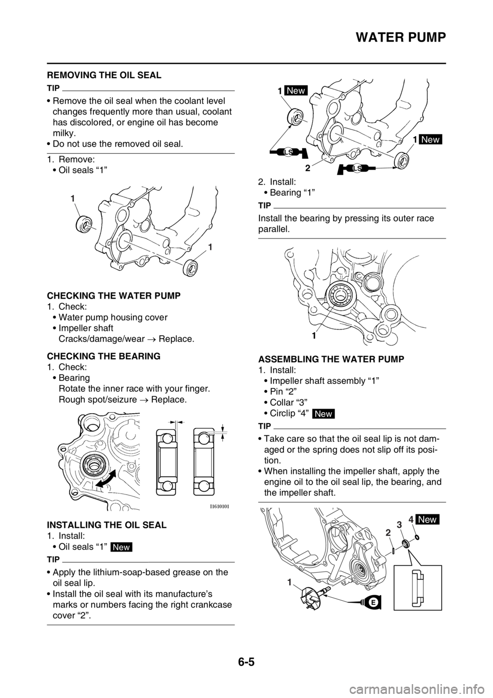
EASB111298REMOVING THE OIL SEAL
TIP
• Remove the oil seal when the coolant level
changes frequently more than usual, coolant
has discolored, or engine oil has become
milky.
• Do not use the removed oil seal.
1. Remove:
• Oil seals “1”
EASB111299CHECKING THE WATER PUMP
1. Check:
• Water pump housing cover
• Impeller shaft
Cracks/damage/wear Replace.
EASB111300CHECKING THE BEARING
1. Check:
• Bearing
Rotate the inner race with your finger.
Rough spot/seizure Replace.
EASB111301INSTALLING THE OIL SEAL
1. Install:
• Oil seals “1”
TIP
• Apply the lithium-soap-based grease on the
oil seal lip.
• Install the oil seal with its manufacture’s
marks or numbers facing the right crankcase
cover “2”.2. Install:
• Bearing “1”
TIP
Install the bearing by pressing its outer race
parallel.
EASB111302ASSEMBLING THE WATER PUMP
1. Install:
• Impeller shaft assembly “1”
•Pin “2”
• Collar “3”
• Circlip “4”
TIP
• Take care so that the oil seal lip is not dam-
aged or the spring does not slip off its posi-
tion.
• When installing the impeller shaft, apply the
engine oil to the oil seal lip, the bearing, and
the impeller shaft.
1 1
New
1 1New
New
LS
LS2
New
4
1
23New
E
Page 343 of 362
TROUBLESHOOTING
9-2
3. Ignition system
• Faulty ECU
• Faulty crankshaft position sensor
• Broken generator rotor woodruff key
EASB111352POOR MEDIUM-AND-HIGH-SPEED PER-
FORMANCE
Refer to “STARTING FAILURES” on page 9-1.
Engine
1. Air filter
• Clogged air filter element
Fuel system
1. Fuel pump
• Faulty fuel pump
2. Throttle body
• Defective throttle body
3. ECU
• Faulty ECU
EASB111353SHIFTING IS DIFFICULT
Refer to “CLUTCH” on page 5-38.
EASB111354SHIFT PEDAL DOES NOT MOVE
Engine
1. Shift shaft
• Bent shift shaft
2. Shift drum and shift forks
• Foreign object in a shift drum groove
• Seized shift fork
• Bent shift fork guide bar
3. Transmission
• Seized transmission gear
• Foreign object between transmission gears
• Improperly assembled transmission
EASB111355JUMPS OUT OF GEAR
Engine
1. Shift shaft
• Incorrect shift pedal position
• Improperly returned stopper lever
2. Shift forks
• Worn shift fork
3. Shift drum
• Incorrect axial play
• Worn shift drum groove
4. Transmission
• Worn gear dog
EASB111356
CLUTCH SLIPS
Engine
1. Clutch
• Improperly assembled clutch
• Loose or fatigued clutch spring
• Worn friction plate
• Worn clutch plate
2. Engine oil
• Incorrect oil level
• Incorrect oil viscosity (low)
• Deteriorated oil
EASB111357CLUTCH DRAGS
Engine
1. Clutch
• Unevenly tensioned clutch springs
• Warped pressure plate
• Bent clutch plate
• Swollen friction plate
• Bent clutch push rod
• Damaged clutch boss
• Burnt primary driven gear bushing
2. Engine oil
• Incorrect oil level
• Incorrect oil viscosity (high)
• Deteriorated oil
EASB111358OVERHEATING
Engine
1. Cylinder head and piston
• Heavy carbon buildup
• Clogged coolant passages
2. Engine oil
• Incorrect oil level
• Incorrect oil viscosity
• Inferior oil quality
Cooling system
1. Coolant
• Low coolant level
2. Radiator
• Damaged or leaking radiator
• Faulty radiator cap
• Bent or damaged radiator fin
3. Water pump
• Damaged or faulty water pump
• Damaged hose
• Improperly connected hose
• Damaged pipe
• Improperly connected pipe
Page 344 of 362
TROUBLESHOOTING
9-3
Fuel system
1. Throttle body
• Damaged or loose throttle body joint
2. Air filter
• Clogged air filter element
Chassis
1. Brake(s)
• Dragging brake
Electrical system
1. Spark plug
• Incorrect spark plug gap
• Incorrect spark plug heat range
2. Ignition system
• Faulty ECU
• Faulty coolant temperature sensor
EASB111359OVERCOOLING
Cooling system
1. Coolant temperature sensor
• Faulty coolant temperature sensor
EASB111360POOR BRAKING PERFORMANCE
Chassis
1. Brake(s)
• Worn brake pad
• Worn brake disc
• Air in hydraulic brake system
• Leaking brake fluid
• Defective master cylinder kit
• Faulty brake caliper kit
• Faulty brake caliper seal
• Loose union bolt
• Damaged brake hose
• Oil or grease on the brake disc
• Oil or grease on the brake pad
• Incorrect brake fluid level
EASB111361FRONT FORK OIL LEAKING
Chassis
1. Front fork
• Bent, damaged, or rusty inner tube
• Cracked or damaged outer tube
• Improperly installed oil seal
• Damaged oil seal lip
• Incorrect oil level (high)
• Loose damper rod assembly bolt
• Damaged damper rod assembly bolt copper
washer
• Cracked or damaged cap bolt O-ring
EASB111362FAULTY FRONT FORK LEGS
Chassis
1. Front fork
• Bent or damaged inner tube
• Bent or damaged outer tube
• Broken fork spring
• Bent or damaged damper rod
• Incorrect oil viscosity
• Incorrect oil level
EASB111363UNSTABLE HANDLING
Chassis
1. Handlebar
• Bent or improperly installed handlebar
2. Steering head components
• Improperly installed upper bracket
• Improperly installed lower bracket
(improperly tightened ring nut)
• Bent steering stem
• Damaged ball bearing or bearing race
3. Front fork leg (s)
• Uneven oil levels (both front fork legs)
• Unevenly tensioned fork spring (both front
fork legs)
• Broken fork spring
• Bent or damaged inner tube
• Bent or damaged outer tube
4. Swingarm
• Worn bearing or bushing
• Bent or damaged swingarm
5. Rear shock absorber assembly (-ies)
• Faulty rear shock absorber spring
• Leaking oil or gas
6. Tire (s)
• Uneven tire pressures (front and rear)
• Incorrect tire pressure
• Uneven tire wear
7. Wheel (s)
• Incorrect wheel balance
• Broken or loose spoke
• Damaged wheel bearing
• Bent or loose wheel axle
• Excessive wheel runout
8. Frame
• Bent frame
• Damaged steering head pipe
• Improperly installed bearing race