tow bar YAMAHA YZ450F 2016 Owners Manual
[x] Cancel search | Manufacturer: YAMAHA, Model Year: 2016, Model line: YZ450F, Model: YAMAHA YZ450F 2016Pages: 362, PDF Size: 10.49 MB
Page 32 of 362

CONTROL FUNCTIONS
1-18
EASB111029
CONTROL FUNCTIONS
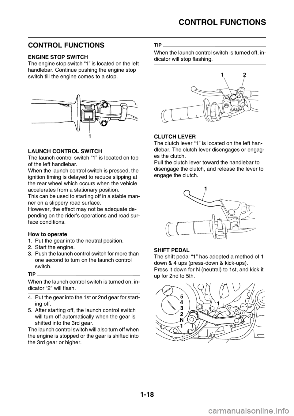
EASB111030ENGINE STOP SWITCH
The engine stop switch “1” is located on the left
handlebar. Continue pushing the engine stop
switch till the engine comes to a stop.
EASB111031LAUNCH CONTROL SWITCH
The launch control switch “1” is located on top
of the left handlebar.
When the launch control switch is pressed, the
ignition timing is delayed to reduce slipping at
the rear wheel which occurs when the vehicle
accelerates from a stationary position.
This can be used to starting off in a stable man-
ner on a slippery road surface.
However, the effect may not be adequate de-
pending on the rider’s operations and road sur-
face conditions.
How to operate
1. Put the gear into the neutral position.
2. Start the engine.
3. Push the launch control switch for more than
one second to turn on the launch control
switch.
TIP
When the launch control switch is turned on, in-
dicator “2” will flash.
4. Put the gear into the 1st or 2nd gear for start-
ing off.
5. After starting off, the launch control switch
will turn off automatically when the gear is
shifted into the 3rd gear.
The launch control switch will also turn off when
the engine is stopped or the gear is shifted into
the 3rd gear or higher.
TIP
When the launch control switch is turned off, in-
dicator will stop flashing.
EASB111032CLUTCH LEVER
The clutch lever “1” is located on the left han-
dlebar. The clutch lever disengages or engag-
es the clutch.
Pull the clutch lever toward the handlebar to
disengage the clutch, and release the lever to
engage the clutch.
EASB111033SHIFT PEDAL
The shift pedal “1” has adopted a method of 1
down & 4 ups (press-down & kick-ups).
Press it down for N (neutral) to 1st, and kick it
up for 2nd to 5th.
12
Page 33 of 362

CONTROL FUNCTIONS
1-19
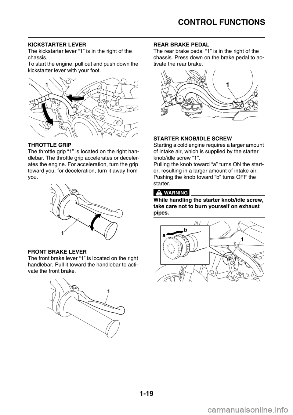
EASB111034KICKSTARTER LEVER
The kickstarter lever “1” is in the right of the
chassis.
To start the engine, pull out and push down the
kickstarter lever with your foot.
EASB111035THROTTLE GRIP
The throttle grip “1” is located on the right han-
dlebar. The throttle grip accelerates or deceler-
ates the engine. For acceleration, turn the grip
toward you; for deceleration, turn it away from
you.
EASB111036FRONT BRAKE LEVER
The front brake lever “1” is located on the right
handlebar. Pull it toward the handlebar to acti-
vate the front brake.
EASB111037REAR BRAKE PEDAL
The rear brake pedal “1” is in the right of the
chassis. Press down on the brake pedal to ac-
tivate the rear brake.
EASB111038STARTER KNOB/IDLE SCREW
Starting a cold engine requires a larger amount
of intake air, which is supplied by the starter
knob/idle screw “1”.
Pulling the knob toward “a” turns ON the start-
er, resulting in a larger amount of intake air.
Pushing the knob toward “b” turns OFF the
starter.
EWA
WARNING
While handling the starter knob/idle screw,
take care not to burn yourself on exhaust
pipes.
1
1
1
ab1
Page 145 of 362

FRONT BRAKE
4-21
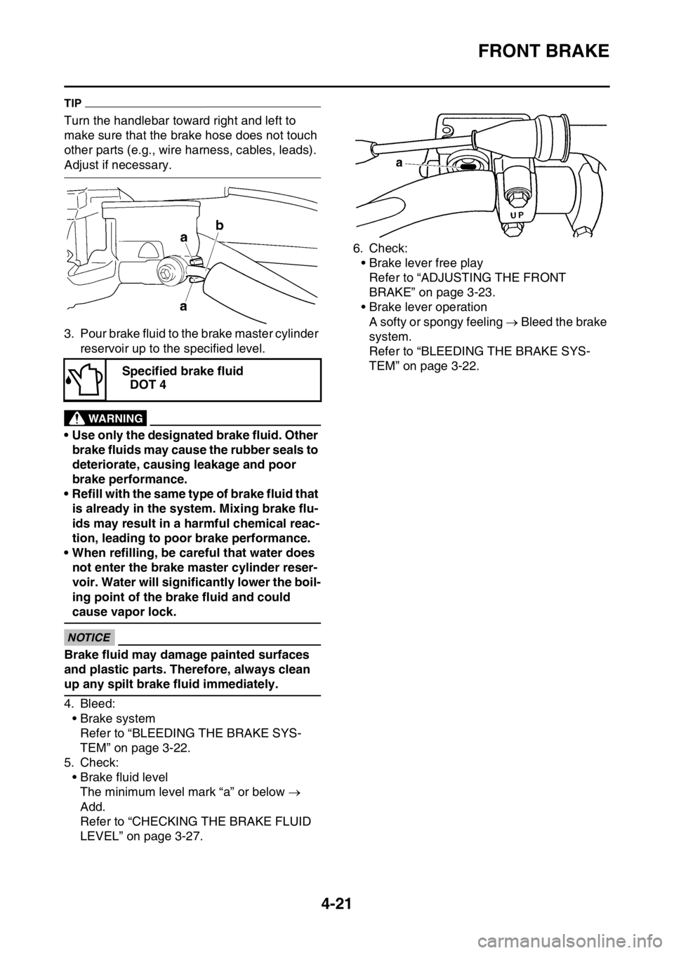
TIP
Turn the handlebar toward right and left to
make sure that the brake hose does not touch
other parts (e.g., wire harness, cables, leads).
Adjust if necessary.
3. Pour brake fluid to the brake master cylinder
reservoir up to the specified level.
EWA13540
WARNING
• Use only the designated brake fluid. Other
brake fluids may cause the rubber seals to
deteriorate, causing leakage and poor
brake performance.
• Refill with the same type of brake fluid that
is already in the system. Mixing brake flu-
ids may result in a harmful chemical reac-
tion, leading to poor brake performance.
• When refilling, be careful that water does
not enter the brake master cylinder reser-
voir. Water will significantly lower the boil-
ing point of the brake fluid and could
cause vapor lock.
ECA13540
NOTICE
Brake fluid may damage painted surfaces
and plastic parts. Therefore, always clean
up any spilt brake fluid immediately.
4. Bleed:
• Brake system
Refer to “BLEEDING THE BRAKE SYS-
TEM” on page 3-22.
5. Check:
• Brake fluid level
The minimum level mark “a” or below
Add.
Refer to “CHECKING THE BRAKE FLUID
LEVEL” on page 3-27.6. Check:
• Brake lever free play
Refer to “ADJUSTING THE FRONT
BRAKE” on page 3-23.
• Brake lever operation
A softy or spongy feeling Bleed the brake
system.
Refer to “BLEEDING THE BRAKE SYS-
TEM” on page 3-22.
Specified brake fluid
DOT 4