engine YAMAHA YZ85 2002 Notices Demploi (in French)
[x] Cancel search | Manufacturer: YAMAHA, Model Year: 2002, Model line: YZ85, Model: YAMAHA YZ85 2002Pages: 504, PDF Size: 40.45 MB
Page 462 of 504

7 - 1
TUN
EC700000
TUNING
EC710000
ENGINE
Carburetor setting
lThe role of fuel is to cool the engine, and in
the case of a 2-stroke engine, to lubricate the
engine in addition to power generation.
Accordingly, if a mixture of air and fuel is too
lean, abnormal combustion will occur, and
engine seizure may result. If the mixture is
too rich, spark plugs will get wet with oil, thus
making it impossible to bring the engine into
full play or if the worst comes to the worst,
the engine may stall.
lThe richness of the air-fuel mixture required
for the engine will vary with atmospheric con-
ditions of the day and therefore, the settings
of the carburetor must be properly suited to
the atmospheric conditions (air pressure,
humidity and temperature).
lFinally, the rider himself must make a test
run and check his machine for conditions
(pick-up of engine speed, road surface con-
ditions) and for the discoloration of the spark
plug(s).
After taking these into consideration, he must
select the best possible carburetor settings.
* It is advisable to make a note of settings,
atmospheric conditions, road surface condi-
tion, lap-time, etc. so that the memorandum
can be used as a reference useful for future.
Atmospheric conditions and carburetor
settings
The air density (i.e., concentration of oxygen
in the air) determines the richness or lean-
ness of the air/fuel mixture. Therefore, refer
to the above table for mixture settings.
Air temp. HumidityAir
pressure
(altitude)Mixture Setting
High High Low (high) Richer Leaner
Low Low High (low) Leaner Richer
SETTING
7
Page 464 of 504
7 - 2
TUN
That is:
lHigher temperature expands the air with its
resultant reduced density.
lHigher humidity reduces the amount of oxy-
gen in the air by so much of the water vapor
in the same air.
lLower atmospheric pressure (at a high alti-
tude) reduces the density of the air.
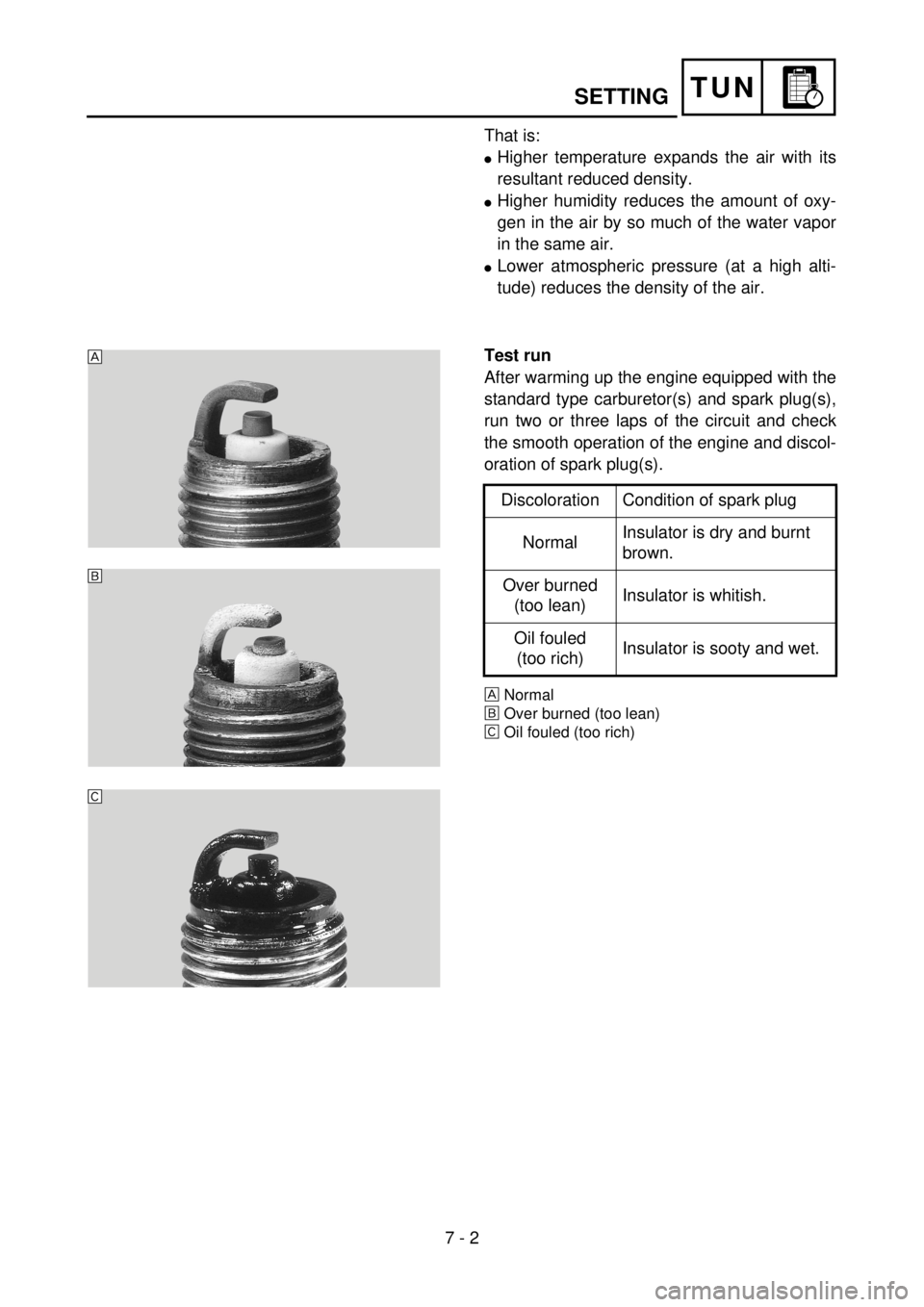
Test run
After warming up the engine equipped with the
standard type carburetor(s) and spark plug(s),
run two or three laps of the circuit and check
the smooth operation of the engine and discol-
oration of spark plug(s).
ÈNormal
ÉOver burned (too lean)
ÊOil fouled (too rich)
Discoloration Condition of spark plug
NormalInsulator is dry and burnt
brown.
Over burned
(too lean)Insulator is whitish.
Oil fouled
(too rich)Insulator is sooty and wet.
5PA70010
È
É
Ê
SETTING
Page 470 of 504
7 - 5
TUNSETTING
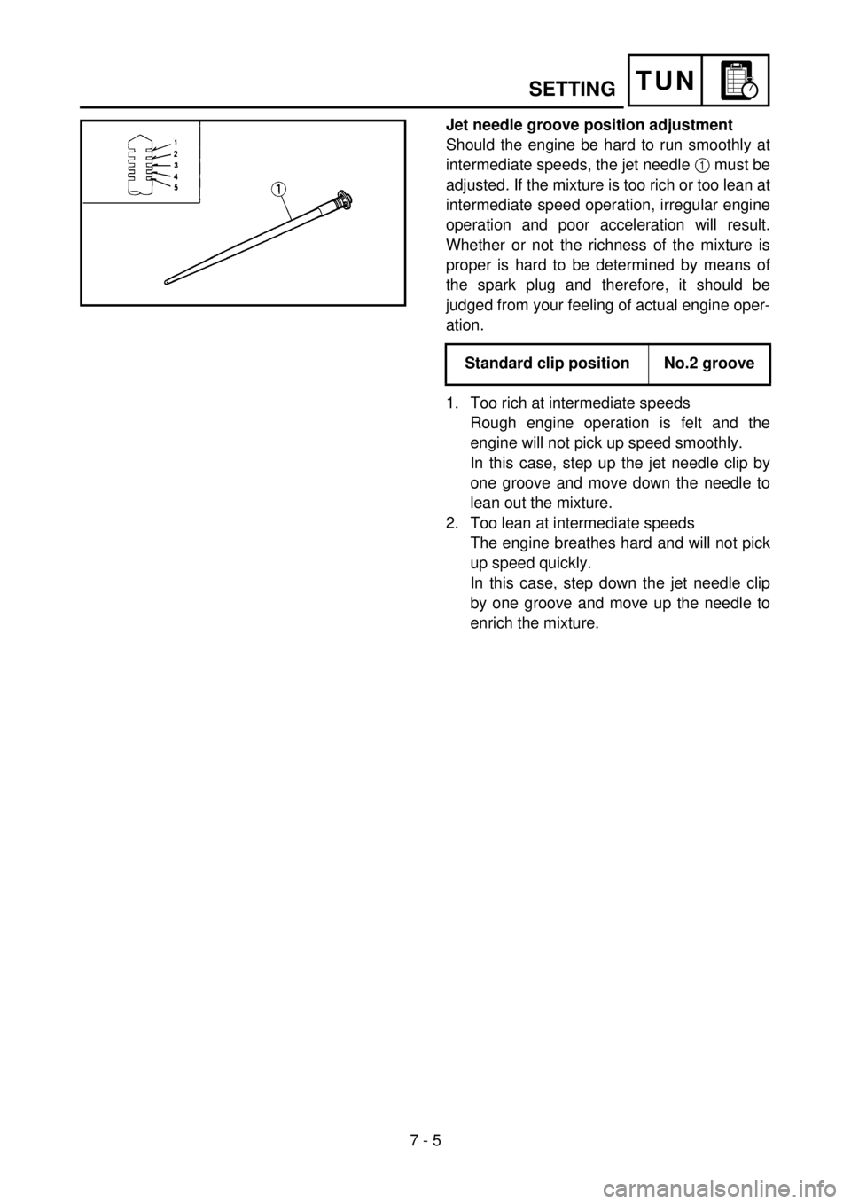
Jet needle groove position adjustment
Should the engine be hard to run smoothly at
intermediate speeds, the jet needle 1 must be
adjusted. If the mixture is too rich or too lean at
intermediate speed operation, irregular engine
operation and poor acceleration will result.
Whether or not the richness of the mixture is
proper is hard to be determined by means of
the spark plug and therefore, it should be
judged from your feeling of actual engine oper-
ation.
1. Too rich at intermediate speeds
Rough engine operation is felt and the
engine will not pick up speed smoothly.
In this case, step up the jet needle clip by
one groove and move down the needle to
lean out the mixture.
2. Too lean at intermediate speeds
The engine breathes hard and will not pick
up speed quickly.
In this case, step down the jet needle clip
by one groove and move up the needle to
enrich the mixture. Standard clip position No.2 groove
5PA70090
Page 474 of 504
7 - 7
TUN
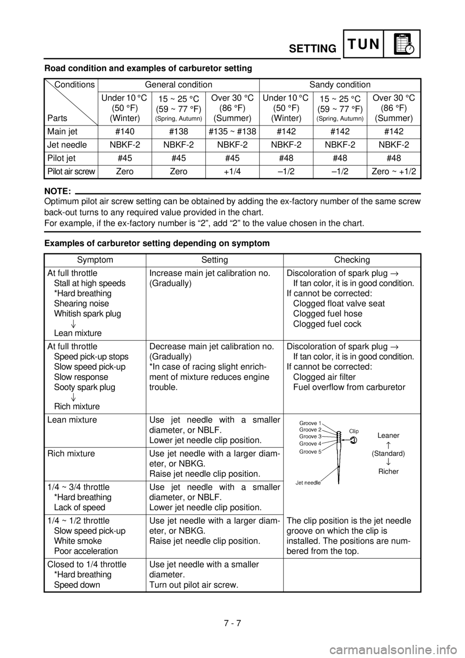
Road condition and examples of carburetor setting
NOTE:
Optimum pilot air screw setting can be obtained by adding the ex-factory number of the same screw
back-out turns to any required value provided in the chart.
For example, if the ex-factory number is “2”, add “2” to the value chosen in the chart.
Examples of carburetor setting depending on symptomConditions
PartsGeneral condition Sandy condition
Under 10 °C
(50 °F)
(Winter)15 ~ 25 °C
(59 ~ 77 °F)
(Spring, Autumn)
Over 30 °C
(86 °F)
(Summer)Under 10 °C
(50 °F)
(Winter)15 ~ 25 °C
(59 ~ 77 °F)
(Spring, Autumn)
Over 30 °C
(86 °F)
(Summer)
Main jet #140 #138 #135 ~ #138 #142 #142 #142
Jet needle NBKF-2 NBKF-2 NBKF-2 NBKF-2 NBKF-2 NBKF-2
Pilot jet #45 #45 #45 #48 #48 #48
Pilot air screw Zero Zero +1/4 –1/2 –1/2 Zero ~ +1/2
Symptom Setting Checking
At full throttle
Stall at high speeds
*Hard breathing
Shearing noise
Whitish spark plug
Lean mixtureIncrease main jet calibration no.
(Gradually)Discoloration of spark plug ®
If tan color, it is in good condition.
If cannot be corrected:
Clogged float valve seat
Clogged fuel hose
Clogged fuel cock
At full throttle
Speed pick-up stops
Slow speed pick-up
Slow response
Sooty spark plug
Rich mixtureDecrease main jet calibration no.
(Gradually)
*In case of racing slight enrich-
ment of mixture reduces engine
trouble.Discoloration of spark plug ®
If tan color, it is in good condition.
If cannot be corrected:
Clogged air filter
Fuel overflow from carburetor
Lean mixture Use jet needle with a smaller
diameter, or NBLF.
Lower jet needle clip position.
The clip position is the jet needle
groove on which the clip is
installed. The positions are num-
bered from the top. Rich mixture Use jet needle with a larger diam-
eter, or NBKG.
Raise jet needle clip position.
1/4 ~ 3/4 throttle
*Hard breathing
Lack of speedUse jet needle with a smaller
diameter, or NBLF.
Lower jet needle clip position.
1/4 ~ 1/2 throttle
Slow speed pick-up
White smoke
Poor accelerationUse jet needle with a larger diam-
eter, or NBKG.
Raise jet needle clip position.
Closed to 1/4 throttle
*Hard breathing
Speed downUse jet needle with a smaller
diameter.
Turn out pilot air screw.
Leaner
(Standard)
¯
Richer
SETTING
Page 475 of 504

7 - 8
TUN
* marked: In case of hard breathing, check the carburetor breather hoses for clogging. Closed to 1/4 throttle
Poor acceleration
White smokeUse jet needle with a larger diam-
eter.
Turn in pilot air screw.
Unstable at low speeds
Pinking noiseLower jet needle clip position.
(1 groove down)
Turn in pilot air screw.
Poor response at
extremely low speedReduce pilot jet calibration No.
Turn out pilot air screw.
If not effect, reverse the above
procedures.Dragging brake
Overflow from carburetor
Poor response in the low
to intermediate speedsRaise jet needle clip position.
If this has no effect, lower the jet
needle clip position.
Poor response when
throttle is opened quicklyCheck overall settings.
Use main jet with a lower calibra-
tion no.
Raise jet needle clip position.
Use jet needle with a larger diam-
eter.
If these have no effect, use a main
jet with a higher calibration no.
and lower the jet needle clip posi-
tion.Check air filter for fouling.
Poor engine operation Turn in pilot air screw.
Adjust the throttle stop screw.Check throttle valve operation. Symptom Setting Checking
This should be taken simply for an example. It
is necessary to set the carburetor while check-
ing the operating conditions of the engine and
discoloration of spark plugs.
Normally, carburetor setting is made by means
of the main jet, jet needle clip position, pilot jet
and pilot air screw.
SETTING
Page 480 of 504
7 - 9
TUNSETTING
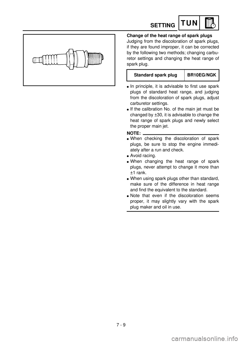
Change of the heat range of spark plugs
Judging from the discoloration of spark plugs,
if they are found improper, it can be corrected
by the following two methods; changing carbu-
retor settings and changing the heat range of
spark plug.
lIn principle, it is advisable to first use spark
plugs of standard heat range, and judging
from the discoloration of spark plugs, adjust
carburetor settings.
lIf the calibration No. of the main jet must be
changed by ±30, it is advisable to change the
heat range of spark plugs and newly select
the proper main jet.
NOTE:
lWhen checking the discoloration of spark
plugs, be sure to stop the engine immedi-
ately after a run and check.
lAvoid racing.
lWhen changing the heat range of spark
plugs, never attempt to change it more than
±1 rank.
lWhen using spark plugs other than standard,
make sure of the difference in heat range
and find the equivalent to the standard.
lNote that even if the discoloration seems
proper, it may slightly vary with the spark
plug maker and oil in use.Standard spark plug BR10EG/NGK
5PA70110
Page 482 of 504

7 - 10
TUNSETTING
EC720000
CHASSIS
Selection of the secondary reduction ratio
(Sprocket)
Secondary
reduction =
ratio
lIt is generally said that the secondary gear
ratio should be reduced for a longer straight
portion of a speed course and should be
increased for a course with many corners.
Actually, however, as the speed depends on
the ground condition of the day of the race,
be sure to run through the circuit to set the
machine suitable for the entire course.
lIn actuality, it is very difficult to achieve set-
tings suitable for the entire course and some
settings may be sacrificed. Thus, the settings
should be matched to the portion of the
course that has the greatest effect on the
race result. In such a case, run through the
entire course while making notes of lap times
to find the best balance; then, determine the
secondary reduction ratio.
lIf a course has a long straight portion where
a machine can run at maximum speed, the
machine is generally set such that it can
develop its maximum revolutions toward the
end of the straight line, with care taken to
avoid the engine over-revving.
NOTE:
Riding technique varies from rider to rider and
the performance of a machine also vary from
machine to machine. Therefore, do not imitate
other rider’s settings from the beginning but
choose your own setting according to the level
of your riding technique.Standard secondary
reduction ratioYZ85:
47/14 (3.357)
(USA, S, NZ, ZA)
48/14 (3.429)
(F, D, I, GB, E,
CDN, AUS)
YZ85LW:
52/14 (3.714)
Number of rear wheel sprocket teeth
Number of drive sprocket teeth
Page 492 of 504
7 - 15
TUNSETTING
EC72C001
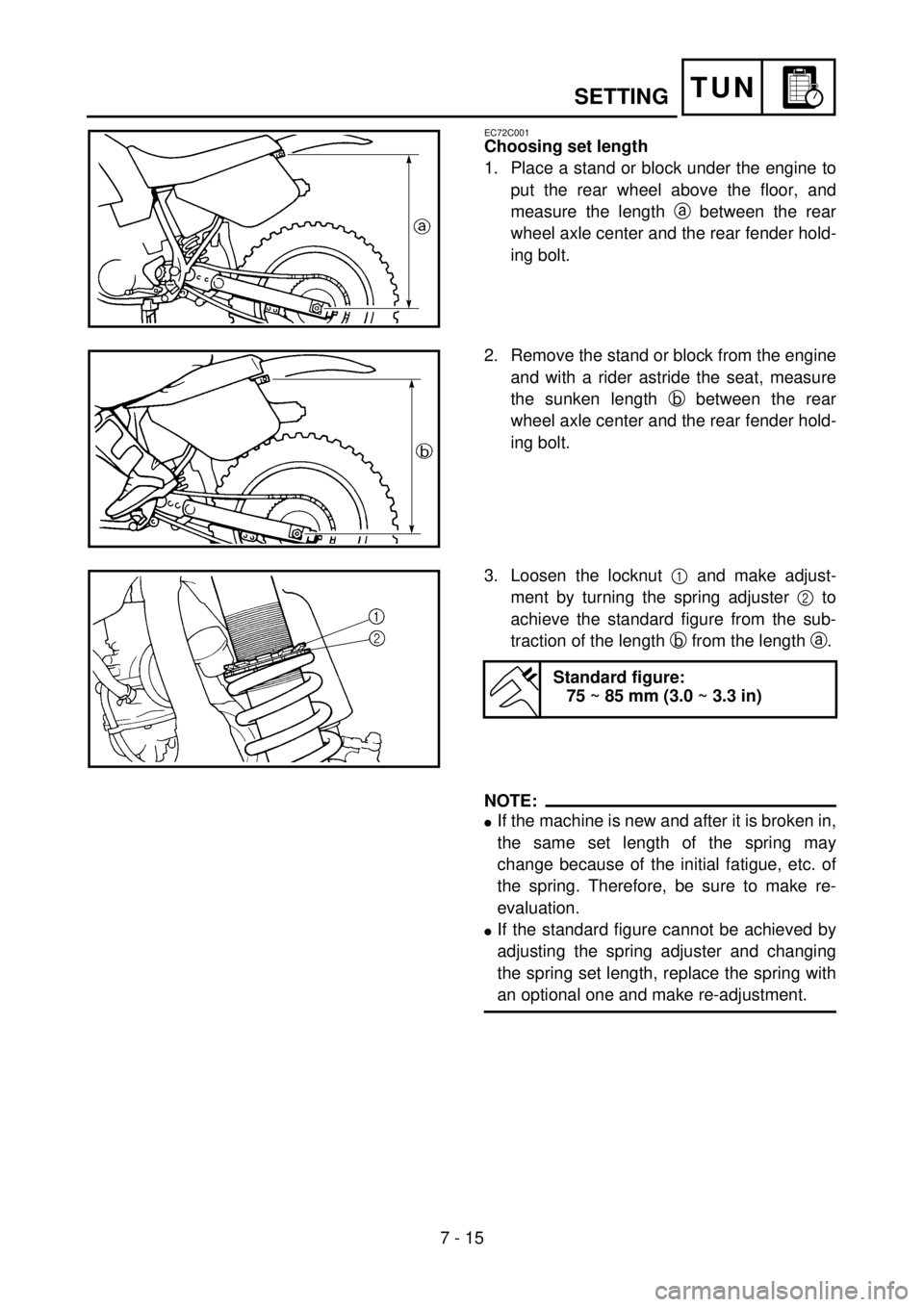
Choosing set length
1. Place a stand or block under the engine to
put the rear wheel above the floor, and
measure the length a between the rear
wheel axle center and the rear fender hold-
ing bolt.
5PA70160
2. Remove the stand or block from the engine
and with a rider astride the seat, measure
the sunken length b between the rear
wheel axle center and the rear fender hold-
ing bolt.
5PA70170
3. Loosen the locknut 1 and make adjust-
ment by turning the spring adjuster 2 to
achieve the standard figure from the sub-
traction of the length b from the length a.
Standard figure:
75 ~ 85 mm (3.0 ~ 3.3 in)
5PA70180
NOTE:
lIf the machine is new and after it is broken in,
the same set length of the spring may
change because of the initial fatigue, etc. of
the spring. Therefore, be sure to make re-
evaluation.
lIf the standard figure cannot be achieved by
adjusting the spring adjuster and changing
the spring set length, replace the spring with
an optional one and make re-adjustment.