oil YAMAHA YZ85 2002 Repair Manual
[x] Cancel search | Manufacturer: YAMAHA, Model Year: 2002, Model line: YZ85, Model: YAMAHA YZ85 2002Pages: 504, PDF Size: 40.45 MB
Page 329 of 504
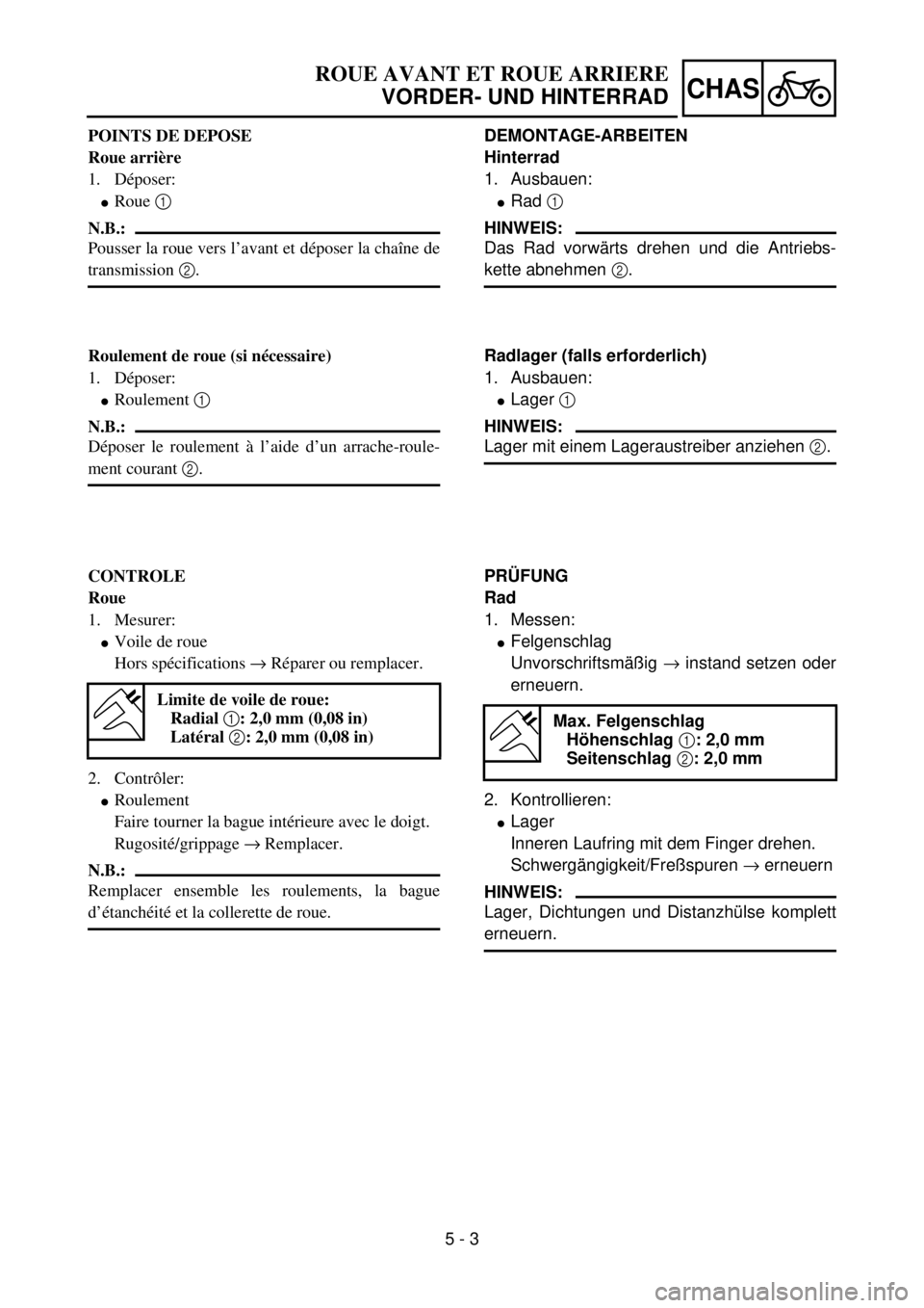
5 - 3
CHAS
POINTS DE DEPOSE
Roue arrière
1. Déposer:
lRoue 1
N.B.:
Pousser la roue vers l’avant et déposer la chaîne de
transmission 2.
Roulement de roue (si nécessaire)
1. Déposer:
lRoulement 1
N.B.:
Déposer le roulement à l’aide d’un arrache-roule-
ment courant 2.
CONTROLE
Roue
1. Mesurer:
lVoile de roue
Hors spécifications ® Réparer ou remplacer.
2. Contrôler:
lRoulement
Faire tourner la bague intérieure avec le doigt.
Rugosité/grippage ® Remplacer.
N.B.:
Remplacer ensemble les roulements, la bague
d’étanchéité et la collerette de roue.
Limite de voile de roue:
Radial 1: 2,0 mm (0,08 in)
Latéral 2: 2,0 mm (0,08 in)
ROUE AVANT ET ROUE ARRIERE
VORDER- UND HINTERRAD
DEMONTAGE-ARBEITEN
Hinterrad
1. Ausbauen:
lRad 1
HINWEIS:
Das Rad vorwärts drehen und die Antriebs-
kette abnehmen 2.
Radlager (falls erforderlich)
1. Ausbauen:
lLager 1
HINWEIS:
Lager mit einem Lageraustreiber anziehen 2.
PRÜFUNG
Rad
1. Messen:
lFelgenschlag
Unvorschriftsmäßig ® instand setzen oder
erneuern.
2. Kontrollieren:
lLager
Inneren Laufring mit dem Finger drehen.
Schwergängigkeit/Freßspuren ® erneuern
HINWEIS:
Lager, Dichtungen und Distanzhülse komplett
erneuern.
Max. Felgenschlag
Höhenschlag
1: 2,0 mm
Seitenschlag
2: 2,0 mm
Page 331 of 504
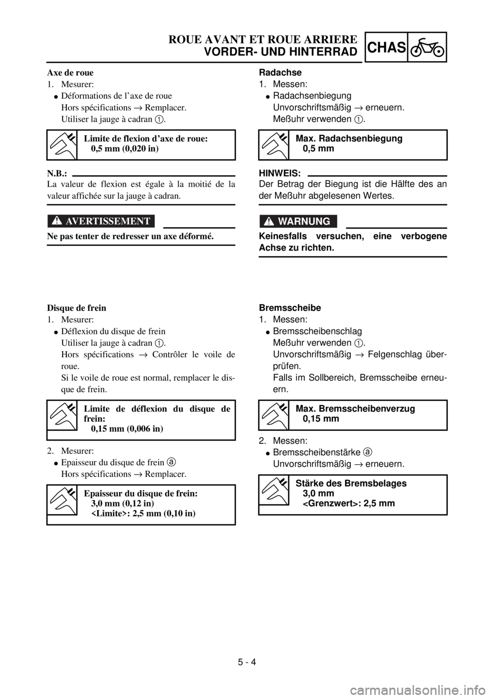
5 - 4
CHAS
Axe de roue
1. Mesurer:
lDéformations de l’axe de roue
Hors spécifications ® Remplacer.
Utiliser la jauge à cadran 1.
N.B.:
La valeur de flexion est égale à la moitié de la
valeur affichée sur la jauge à cadran.
AVERTISSEMENT
Ne pas tenter de redresser un axe déformé.
Limite de flexion d’axe de roue:
0,5 mm (0,020 in)
Disque de frein
1. Mesurer:
lDéflexion du disque de frein
Utiliser la jauge à cadran 1.
Hors spécifications ® Contrôler le voile de
roue.
Si le voile de roue est normal, remplacer le dis-
que de frein.
2. Mesurer:
lEpaisseur du disque de frein a
Hors spécifications ® Remplacer.
Limite de déflexion du disque de
frein:
0,15 mm (0,006 in)
Epaisseur du disque de frein:
3,0 mm (0,12 in)
ROUE AVANT ET ROUE ARRIERE
VORDER- UND HINTERRAD
Radachse
1. Messen:
lRadachsenbiegung
Unvorschriftsmäßig ® erneuern.
Meßuhr verwenden 1.
HINWEIS:
Der Betrag der Biegung ist die Hälfte des an
der Meßuhr abgelesenen Wertes.
WARNUNG
Keinesfalls versuchen, eine verbogene
Achse zu richten.
Max. Radachsenbiegung
0,5 mm
Bremsscheibe
1. Messen:
lBremsscheibenschlag
Meßuhr verwenden 1.
Unvorschriftsmäßig ® Felgenschlag über-
prüfen.
Falls im Sollbereich, Bremsscheibe erneu-
ern.
2. Messen:
lBremsscheibenstärke a
Unvorschriftsmäßig ® erneuern.
Max. Bremsscheibenverzug
0,15 mm
Stärke des Bremsbelages
3,0 mm
Page 332 of 504
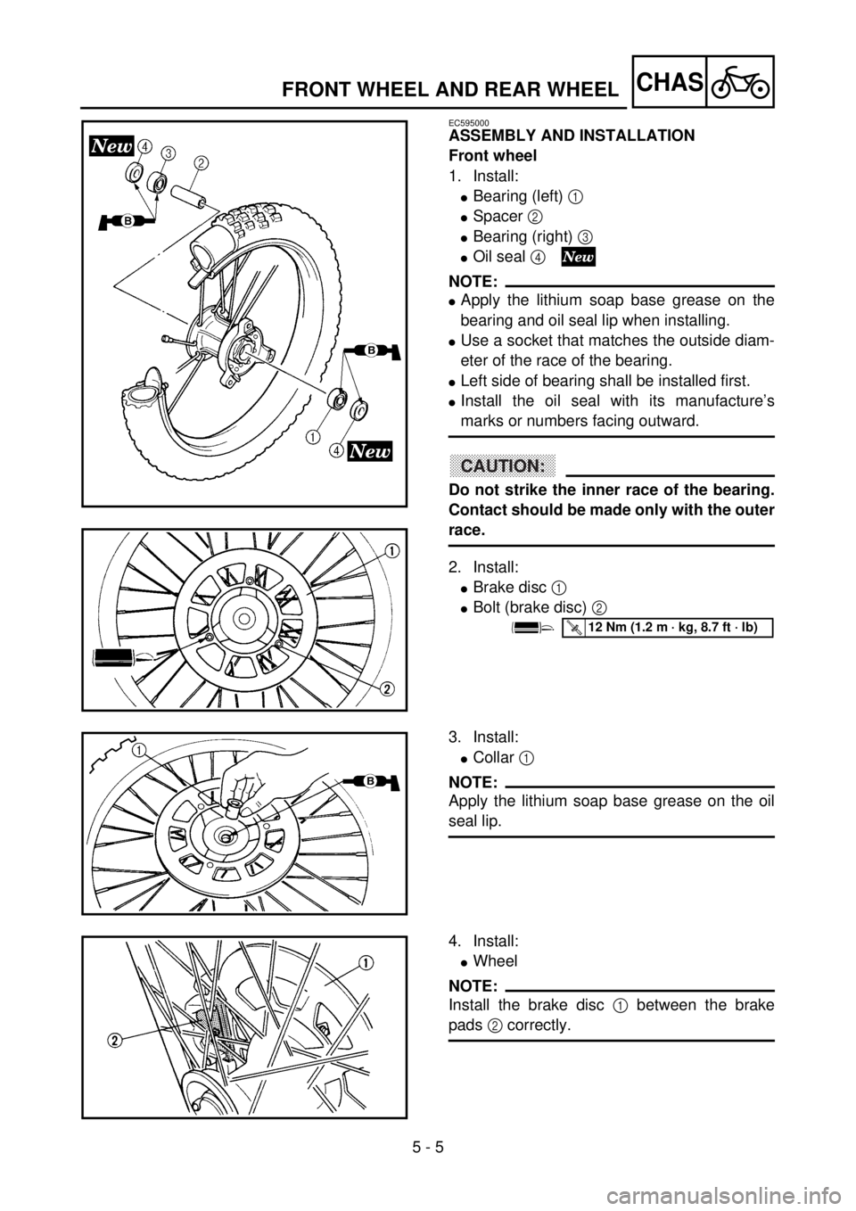
5 - 5
CHAS
EC595000
ASSEMBLY AND INSTALLATION
Front wheel
1. Install:
lBearing (left) 1
lSpacer 2
lBearing (right) 3
lOil seal 4
NOTE:
lApply the lithium soap base grease on the
bearing and oil seal lip when installing.
lUse a socket that matches the outside diam-
eter of the race of the bearing.
lLeft side of bearing shall be installed first.
lInstall the oil seal with its manufacture’s
marks or numbers facing outward.
CAUTION:
Do not strike the inner race of the bearing.
Contact should be made only with the outer
race.
2. Install:
lBrake disc 1
lBolt (brake disc) 2
5PA50090
5PA50100
T R..12 Nm (1.2 m · kg, 8.7 ft · lb)
3. Install:
lCollar 1
NOTE:
Apply the lithium soap base grease on the oil
seal lip.
5PA50110
4. Install:
lWheel
NOTE:
Install the brake disc 1 between the brake
pads 2 correctly.
5PA50120
FRONT WHEEL AND REAR WHEEL
Page 334 of 504
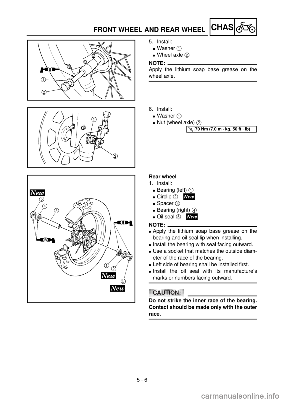
5 - 6
CHAS
5. Install:
lWasher 1
lWheel axle 2
NOTE:
Apply the lithium soap base grease on the
wheel axle.
5PA50130
6. Install:
lWasher 1
lNut (wheel axle) 2
5PA50140
T R..70 Nm (7.0 m · kg, 50 ft · lb)
Rear wheel
1. Install:
lBearing (left) 1
lCirclip 2
lSpacer 3
lBearing (right) 4
lOil seal 5
NOTE:
lApply the lithium soap base grease on the
bearing and oil seal lip when installing.
lInstall the bearing with seal facing outward.
lUse a socket that matches the outside diam-
eter of the race of the bearing.
lLeft side of bearing shall be installed first.
lInstall the oil seal with its manufacture’s
marks or numbers facing outward.
CAUTION:
Do not strike the inner race of the bearing.
Contact should be made only with the outer
race.
5PA50150
FRONT WHEEL AND REAR WHEEL
Page 336 of 504

5 - 7
CHAS
2. Install:
lBrake disc 1
lBolt (brake disc) 2
NOTE:
Tighten the bolts (brake disc) in stage, using a
crisscross pattern.
5PA50160
T R..12 Nm (1.2 m · kg, 8.7 ft · lb)
3. Install:
lRear wheel sprocket 1
lBolt (rear wheel sprocket) 2
lWasher (rear wheel sprocket) 3
lNut (rear wheel sprocket) 4
NOTE:
Tighten the nuts (rear wheel sprocket) in
stage, using a crisscross pattern.5PA50170
T R..42 Nm (4.2 m · kg, 30 ft · lb)
4. Install:
lCollar 1
NOTE:
Apply the lithium soap base grease on the oil
seal lip.
5PA50180
5. Install:
lWheel
NOTE:
Install the brake disc 1 between the brake
pads 2 correctly.
5PA50190
6. Install:
lDrive chain 1
NOTE:
Push the wheel 2 forward and install the drive
chain.
5PA50200
FRONT WHEEL AND REAR WHEEL
Page 372 of 504
5 - 25
CHAS
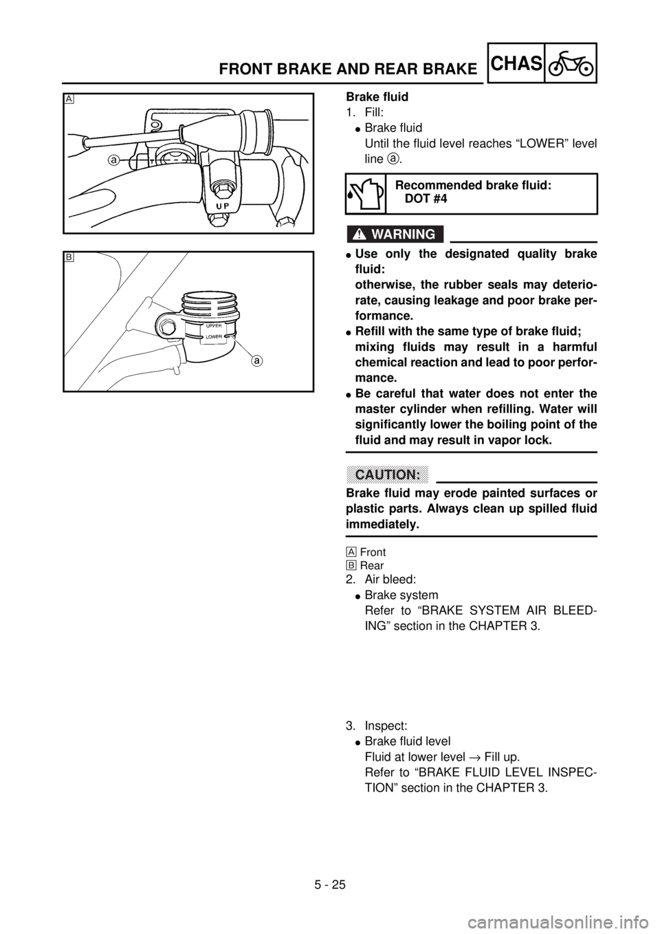
Brake fluid
1. Fill:
lBrake fluid
Until the fluid level reaches “LOWER” level
line a.
WARNING
lUse only the designated quality brake
fluid:
otherwise, the rubber seals may deterio-
rate, causing leakage and poor brake per-
formance.
lRefill with the same type of brake fluid;
mixing fluids may result in a harmful
chemical reaction and lead to poor perfor-
mance.
lBe careful that water does not enter the
master cylinder when refilling. Water will
significantly lower the boiling point of the
fluid and may result in vapor lock.
CAUTION:
Brake fluid may erode painted surfaces or
plastic parts. Always clean up spilled fluid
immediately.
ÈFront
ÉRear
2. Air bleed:
lBrake system
Refer to “BRAKE SYSTEM AIR BLEED-
ING” section in the CHAPTER 3.
Recommended brake fluid:
DOT #4
È
5PA50770
É
5PA50780
3. Inspect:
lBrake fluid level
Fluid at lower level ® Fill up.
Refer to “BRAKE FLUID LEVEL INSPEC-
TION” section in the CHAPTER 3.
FRONT BRAKE AND REAR BRAKE
Page 378 of 504
5 - 28
CHAS
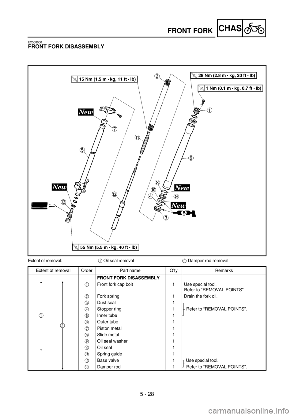
EC558000
FRONT FORK DISASSEMBLY
5PA50830
Extent of removal:
1 Oil seal removal
2 Damper rod removal
Extent of removal Order Part name Q’ty Remarks
FRONT FORK DISASSEMBLY
1 Front fork cap bolt 1 Use special tool.
Refer to “REMOVAL POINTS”.
2 Fork spring 1 Drain the fork oil.
3 Dust seal 1
Refer to “REMOVAL POINTS”.
4 Stopper ring 1
5 Inner tube 1
6 Outer tube 1
7 Piston metal 1
8 Slide metal 1
9 Oil seal washer 1
0 Oil seal 1
A Spring guide 1
B Base valve 1 Use special tool.
C Damper rod 1 Refer to “REMOVAL POINTS”.
1
2
FRONT FORK
Page 380 of 504
5 - 29
CHAS
EC556000
HANDLING NOTE
NOTE:
The front fork requires careful attention. So it is
recommended that the front fork be maintained
at the dealers.
CAUTION:
To prevent an accidental explosion of air,
the following instructions should be
observed:
lThe front fork with a built-in piston rod
has a very sophisticated internal con-
struction and is particularly sensitive to
foreign material.
Use enough care not to allow any foreign
material to come in when the oil is
replaced or when the front fork is disas-
sembled and reassembled.
lBefore removing the cap bolts or front
forks, be sure to extract the air from the
air chamber completely.
EC553000
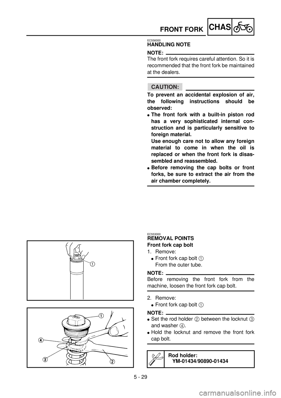
REMOVAL POINTS
Front fork cap bolt
1. Remove:
lFront fork cap bolt 1
From the outer tube.
NOTE:
Before removing the front fork from the
machine, loosen the front fork cap bolt.
2. Remove:
lFront fork cap bolt 1
NOTE:
lSet the rod holder 2 between the locknut 3
and washer 4.
lHold the locknut and remove the front fork
cap bolt.
Rod holder:
YM-01434/90890-01434
5PA50840
5PA50850
FRONT FORK
Page 382 of 504
5 - 30
CHAS
EC553201
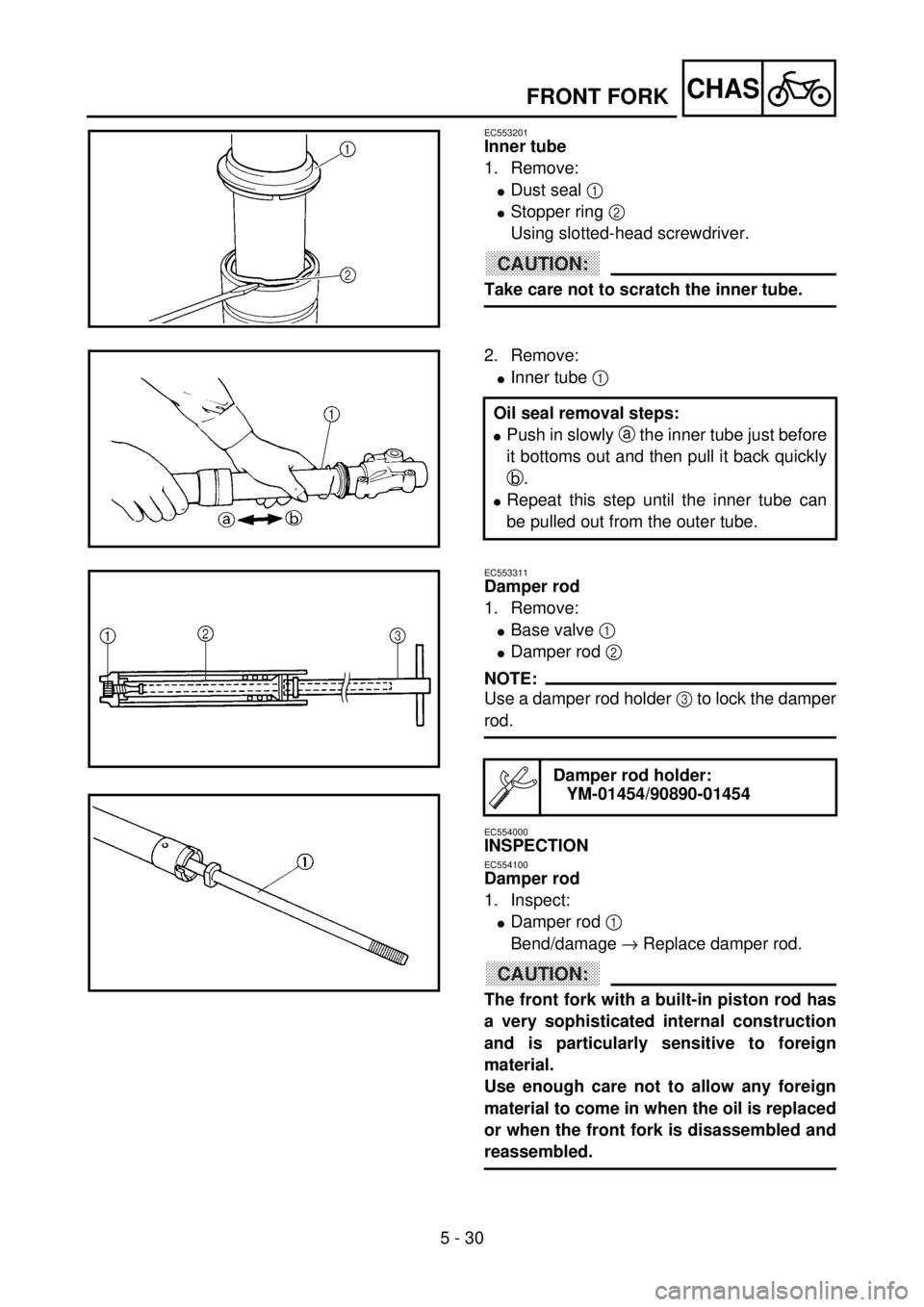
Inner tube
1. Remove:
lDust seal 1
lStopper ring 2
Using slotted-head screwdriver.
CAUTION:
Take care not to scratch the inner tube.
5PA50860
2. Remove:
lInner tube 1
Oil seal removal steps:
lPush in slowly a the inner tube just before
it bottoms out and then pull it back quickly
b.
lRepeat this step until the inner tube can
be pulled out from the outer tube.
5PA50870
EC553311
Damper rod
1. Remove:
lBase valve 1
lDamper rod 2
NOTE:
Use a damper rod holder 3 to lock the damper
rod.
EC554000
INSPECTION
EC554100
Damper rod
1. Inspect:
lDamper rod 1
Bend/damage ® Replace damper rod.
CAUTION:
The front fork with a built-in piston rod has
a very sophisticated internal construction
and is particularly sensitive to foreign
material.
Use enough care not to allow any foreign
material to come in when the oil is replaced
or when the front fork is disassembled and
reassembled.
Damper rod holder:
YM-01454/90890-01454
5PA50880
5PA50890
FRONT FORK
Page 384 of 504
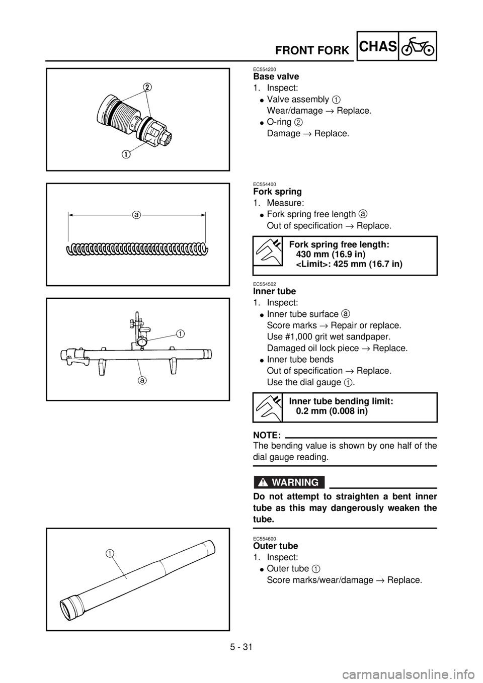
5 - 31
CHAS
EC554200
Base valve
1. Inspect:
lValve assembly 1
Wear/damage ® Replace.
lO-ring 2
Damage ® Replace.
5PA50900
EC554400
Fork spring
1. Measure:
lFork spring free length a
Out of specification ® Replace.
EC554502
Inner tube
1. Inspect:
lInner tube surface a
Score marks ® Repair or replace.
Use #1,000 grit wet sandpaper.
Damaged oil lock piece ® Replace.
lInner tube bends
Out of specification ® Replace.
Use the dial gauge 1.
NOTE:
The bending value is shown by one half of the
dial gauge reading.
WARNING
Do not attempt to straighten a bent inner
tube as this may dangerously weaken the
tube.
EC554600
Outer tube
1. Inspect:
lOuter tube 1
Score marks/wear/damage ® Replace.
Fork spring free length:
430 mm (16.9 in)
Inner tube bending limit:
0.2 mm (0.008 in)
5PA50910
5PA50920
5PA50930
FRONT FORK