check engine YAMAHA YZ85 2002 Owners Manual
[x] Cancel search | Manufacturer: YAMAHA, Model Year: 2002, Model line: YZ85, Model: YAMAHA YZ85 2002Pages: 504, PDF Size: 40.45 MB
Page 6 of 504

IMPORTANT NOTICE
THIS MACHINE IS DESIGNED STRICTLY
FOR COMPETITION USE, ONLY ON A
CLOSED COURSE. It is illegal for this
machine to be operated on any public street,
road, or highway. Off-road use on public lands
may also be illegal. Please check local regula-
tions before riding.
1. THIS MACHINE IS TO BE OPERATED
BY AN EXPERIENCED RIDER ONLY.
Do not attempt to operate this
machine at maximum power until you
are totally familiar with its character-
istics.
2. THIS MACHINE IS DESIGNED TO BE
RIDDEN BY THE OPERATOR ONLY.
Do not carry passengers on this
machine.
3. ALWAYS WEAR PROTECTIVE
APPAREL.
When operating this machine, always
wear an approved helmet with gog-
gles or a face shield. Also wear heavy
boots, gloves, and protective cloth-
ing. Always wear proper fitting cloth-
ing that will not be caught in any of
the moving parts or controls of the
machine.
4. ALWAYS MAINTAIN YOUR MACHINE
IN PROPER WORKING ORDER.
For safety and reliability, the machine
must be properly maintained. Always
perform the pre-operation checks
indicated in this manual. Correcting a
mechanical problem before you ride
may prevent an accident.
5. GASOLINE IS HIGHLY FLAMMABLE.
Always turn off the engine while refu-
eling. Take care to not spill any gaso-
line on the engine or exhaust system.
Never refuel in the vicinity of an open
flame, or while smoking.
SAFETY INFORMATION
Page 20 of 504

EC0A0000
CONTENTS
CHAPTER 1
GENERAL INFORMATION
DESCRIPTION
........................................... 1-1
MACHINE IDENTIFICATION
..................... 1-2
IMPORTANT INFORMATION
.................... 1-3
CHECKING OF CONNECTION
................. 1-6
SPECIAL TOOLS
...................................... 1-7
CONTROL FUNCTIONS
............................ 1-9
FUEL AND ENGINE MIXING OIL
............ 1-12
STARTING AND BREAK-IN
.................... 1-13
TORQUE-CHECK POINTS
...................... 1-16
CLEANING AND STORAGE
................... 1-17
CHAPTER 2
SPECIFICATIONS
GENERAL SPECIFICATIONS
................... 2-1
MAINTENANCE SPECIFICATIONS
.......... 2-4
ENGINE
................................................... 2-4
CHASSIS
................................................. 2-8
YZ85
..................................................... 2-8
YZ85LW
.............................................. 2-10
ELECTRICAL
........................................ 2-14
GENERAL TORQUE
SPECIFICATIONS
................................... 2-15
DEFINITION OF UNITS
........................... 2-15
CABLE ROUTING DIAGRAM
................. 2-16
Page 52 of 504

1 - 13
GEN
INFO
STARTING AND BREAK-IN
STARTING AND BREAK-IN
CAUTION:
Before starting the machine, perform the
checks in the pre-operation check list.
WARNING
Never start or run the engine in a closed
area. The exhaust fumes are poisonous;
they can cause loss of consciousness and
death in a very short time. Always operate
the machine in a well-ventilated area.
STARTING A COLD ENGINE
1. Shift the transmission into neutral.
2. Turn the fuel cock to “ON” and full open the
starter knob (CHOKE).
3. With the throttle completely closed start the
engine by kicking the kickstarter crank
forthly with firm stroke.
4. Run the engine at idle or slightly higher
until it warms up: this usually takes about
one or two minutes.
5. The engine is warmed up when it responds
normally to the throttle with the starter knob
(CHOKE) turned off.
CAUTION:
Do not warm up the engine for extended
periods.
STARTING A WARM ENGINE
Do not operate the starter knob (CHOKE).
Open the throttle slightly and start the engine
by kicking the kickstarter crank forcefully with
firm stroke.
CAUTION:
Observe the following break-in procedures
during initial operation to ensure optimum
performance and avoid engine damage.
Page 54 of 504

1 - 14
GEN
INFO
STARTING AND BREAK-IN
BREAK-IN PROCEDURES
1. Before starting the engine, fill the fuel tank
with a break-in oil-fuel mixture as follows.
2. Perform the pre-operation checks on the
machine.
3. Start and warm up the engine. Check the
idle speed, and check the operation of the
controls and the engine stop switch.
4. Operate the machine in the lower gears at
moderate throttle openings for five to eight
minutes. Stop and check the spark plug
condition; it will show a rich condition dur-
ing break-in.
5. Allow the engine to cool. Restart the
engine and operate the machine as in the
step above for five minutes. Then, very
briefly shift to the higher gears and check
full-throttle response. Stop and check the
spark plug.
6. After again allowing the engine to cool,
restart and run the machine for five more
minutes. Full throttle and the higher gears
may be used, but sustained full-throttle
operation should be avoided. Check the
spark plug condition.
7. Allow the engine to cool, remove the top
end, and inspect the piston and cylinder.
Remove any high spots on the piston with
#600 grit wet sandpaper. Clean all compo-
nents and carefully reassemble the top
end.
8. Drain the break-in oil-fuel mixture from the
fuel tank and refill with the specified mix.
9. Restart the engine and check the operation
of the machine throughout its entire operat-
ing range. Stop and check the spark plug
condition. Restart the machine and operate
it for about 10 to 15 more minutes. The
machine will now be ready to race.
Mixing oil:
Yamalube “2-R”
Mixing ratio:
15 : 1
Page 56 of 504

1 - 15
GEN
INFO
STARTING AND BREAK-IN
CAUTION:
lAfter the break-in or before each race,
you must check the entire machine for
loose fittings and fasteners as per
“TORQUE-CHECK POINTS”.
Tighten all such fasteners as required.
lWhen any of the following parts have
been replaced, they must be broken in.
CYLINDER AND CRANKSHAFT:
About one hour of break-in operation is
necessary.
PISTON, RING AND GEARS:
These parts require about 30 minutes of
break-in operation at half-throttle or less.
Observe the condition of the engine care-
fully during operation.
Page 58 of 504

GEN
INFO
1 - 16
TORQUE-CHECK POINTS
TORQUE-CHECK POINTS
Frame construction
Combined seat and fuel tank
Engine mounting
Steering Steering stem to
handlebar
Suspension Front Steering stem to front
fork
Rear For link type
Rear Installation of rear
shock absorber
Rear Installation of swin-
garm
Wheel Installation of wheel Front
Rear
Brake Front
Rear
Fuel systemFrame to rear frame
Fuel tank to frame
Frame to engine
Steering stem to upper bracket
Upper bracket to handlebar
Front fork to upper bracket
Front fork to lower bracket
Assembly of links
Link to frame
Link to rear shock absorber
Link to swingarm
Rear shock absorber to frame
Tightening of pivot shaft
Tightening of wheel axle
Tightening of wheel axle
Wheel to rear wheel sprocket
Brake caliper to front fork
Brake disc to wheel
Tightening of union bolt
Brake master cylinder to handlebar
Tightening of bleed screw
Brake caliper to bracket
Brake disc to wheel
Tightening of union bolt
Brake master cylinder to frame
Tightening of bleed screw
Fuel tank to fuel cock
NOTE:
Concerning the tightening torque, refer to
“MAINTENANCE SPECIFICATIONS” section
in the CHAPTER 2.
Page 78 of 504

SPEC
2 - 13
MAINTENANCE SPECIFICATIONS
NOTE:
- marked portion shall be checked for torque tightening after break-in or before each race.Part to be tightened Thread size Q’tyTightening torque
Nm m·kg ft·lb
Nipple (spoke) — 64 3 0.3 2.2
Rear wheel sprocket M8 ´ 1.25 4 42 4.2 30
Rear brake caliper protector M6 ´ 1.0 1 10 1.0 7.2
Engine mounting:
Engine and frame (front) M10 ´ 1.25 1 69 6.9 50
Engine and frame (lower) M10 ´ 1.25 1 69 6.9 50
Pivot shaft and nut M12 ´ 1.25 1 63 6.3 45
Relay arm and frame M10 ´ 1.25 1 54 5.4 39
Relay arm and connecting rod M12 ´ 1.25 1 53 5.3 38
Connecting rod and swingarm M12 ´ 1.25 1 53 5.3 38
Rear shock absorber and frame M10 ´ 1.25 1 36 3.6 25
Rear shock absorber and relay arm M10 ´ 1.25 1 36 3.6 25
Rear frame (upper) M8 ´ 1.25 1 26 2.6 19
Rear frame (lower) M8 ´ 1.25 2 16 1.6 11
Swingarm and brake hose holder M5 ´ — 4 4 0.4 2.9
Drive chain tensioner (upper) M8 ´ 1.25 1 23 2.3 17
Drive chain tensioner (lower) M6 ´ 1.0 1 10 1.0 7.2
Drive chain case M8 ´ 1.25 2 11 1.1 8
Seal guard and swingarm M6 ´ 1.0 2 10 1.0 7.2
Fuel tank M6 ´ 1.0 2 7 0.7 5.1
Fuel cock M6 ´ 1.0 2 4 0.4 2.9
Fuel tank bracket and fuel tank M6 ´ 1.0 4 7 0.7 5.1
Seat set bracket and fuel tank M6 ´ 1.0 1 7 0.7 5.1
Radiator cover M6 ´ 1.0 3 4 0.4 2.9
Front fender M6 ´ 1.0 4 7 0.7 5.1
Rear fender M6 ´ 1.0 4 7 0.7 5.1
Flap guard M6 ´ 1.0 2 7 0.7 5.1
Side cover M6 ´ 1.0 2 7 0.7 5.1
Seat M6 ´ 1.0 2 7 0.7 5.1
Number plate M6 ´ 1.0 1 7 0.7 5.1
Page 127 of 504

3 - 4
INSP
ADJ
PRE-OPERATION INSPECTION AND MAINTENANCE
EC320000
PRE-OPERATION INSPECTION AND MAINTENANCE
Before riding for break-in operation, practice or a race, make sure the machine is in good operating
condition.
Before using this machine, check the following points.
GENERAL INSPECTION AND MAINTENANCE
Item Routine Page
CoolantCheck that coolant is filled up to the radiator cap.
Check the cooling system for leakage.P.3-5 ~ 9
FuelCheck that a fresh mixture of oil and gasoline is filled in the fuel
tank. Check the fuel line for leakage.P.1-12
Transmission oilCheck that the oil level is correct. Check the crankcase for leak-
age.P.3-12 ~ 13
Gear shifter and clutchCheck that gears can be shifted correctly in order and that the
clutch operates smoothly.P.3-9
Throttle grip/HousingCheck that the throttle grip operation and free play are correctly
adjusted. Lubricate the throttle grip and housing, if necessary.P.3-10
Brakes Check the play of front brake and effect of front and rear brake. P.3-16 ~ 21
Drive chainCheck drive chain slack and alignment. Check that the drive
chain is lubricated properly.P.3-22 ~ 24
WheelsCheck for excessive wear and tire pressure. Check for loose
spokes and have no excessive play.P.3-31 ~ 32
SteeringCheck that the handlebar can be turned smoothly and have no
excessive play.P.3-32 ~ 33
Front forks and rear shock
absorberCheck that they operate smoothly and there is no oil leakage. P.3-24 ~ 30
Cables (wires)Check that the clutch and throttle cables move smoothly. Check
that they are not caught when the handlebars are turned or
when the front forks travel up and down.—
Exhaust pipe and silencerCheck that the exhaust pipe is tightly mounted and has no
cracks.P.4-2
Rear wheel sprocket Check that the rear wheel sprocket tightening bolt is not loose. P.3-22
Lubrication Check for smooth operation. Lubricate if necessary. P.3-34
Bolts and nuts Check the chassis and engine for loose bolts and nuts. P.1-16
Lead connectorsCheck that the CDI magneto, CDI unit, and ignition coil are con-
nected tightly.P.1-6
SettingsIs the machine set suitably for the condition of the racing course
and weather or by taking into account the results of test runs
before racing? Are inspection and maintenance completely
done?P.7-1 ~ 19
Page 130 of 504

3 - 5
INSP
ADJ
EC350000
ENGINE
COOLANT LEVEL INSPECTION
WARNING
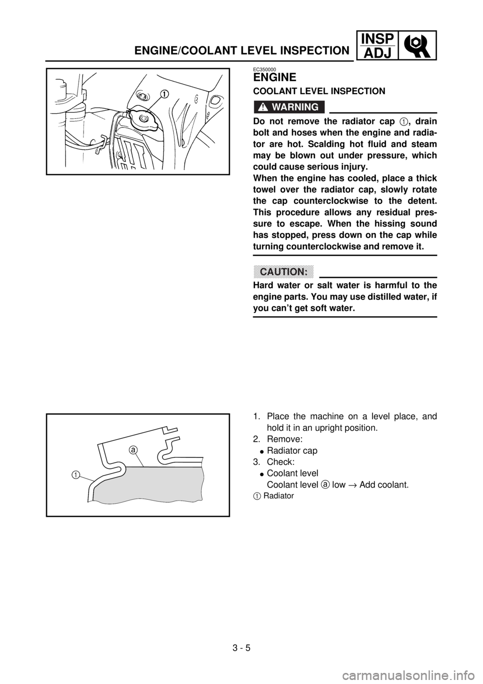
Do not remove the radiator cap
1, drain
bolt and hoses when the engine and radia-
tor are hot. Scalding hot fluid and steam
may be blown out under pressure, which
could cause serious injury.
When the engine has cooled, place a thick
towel over the radiator cap, slowly rotate
the cap counterclockwise to the detent.
This procedure allows any residual pres-
sure to escape. When the hissing sound
has stopped, press down on the cap while
turning counterclockwise and remove it.
CAUTION:
Hard water or salt water is harmful to the
engine parts. You may use distilled water, if
you can’t get soft water.
5PA30010
1. Place the machine on a level place, and
hold it in an upright position.
2. Remove:
lRadiator cap
3. Check:
lCoolant level
Coolant level a low ® Add coolant.
1Radiator
5PA30020
ENGINE/COOLANT LEVEL INSPECTION
Page 134 of 504

3 - 7
INSP
ADJ
RADIATOR CAP INSPECTION
CAUTION:
lDo not mix more than one type of ethyl-
ene glycol antifreeze containing corro-
sion inhibitors for aluminum engine.
lDo not use water containing impurities or
oil.
7. Install:
lRadiator cap
Start the engine and warm it up for a sev-
eral minutes.
8. Check:
lCoolant level
Coolant level low ® Add coolant. Handling notes of coolant:
The coolant is harmful so it should be han-
dled with special care.
WARNING
lWhen coolant splashes to your eye.
Thoroughly wash your eye with water
and see your doctor.
lWhen coolant splashes to your clothes.
Quickly wash it away with water and
then with soap.
lWhen coolant is swallowed.
Quickly make him vomit and take him
to a doctor.
EC355000
RADIATOR CAP INSPECTION
1. Inspect:
lSeal (radiator cap) 1
lValve and valve seat 2
Crack/damage ® Replace.
Exist fur deposits 3 ® Clean or replace.
5PA30050