clock YAMAHA YZ85 2002 Owners Manual
[x] Cancel search | Manufacturer: YAMAHA, Model Year: 2002, Model line: YZ85, Model: YAMAHA YZ85 2002Pages: 504, PDF Size: 40.45 MB
Page 130 of 504

3 - 5
INSP
ADJ
EC350000
ENGINE
COOLANT LEVEL INSPECTION
WARNING
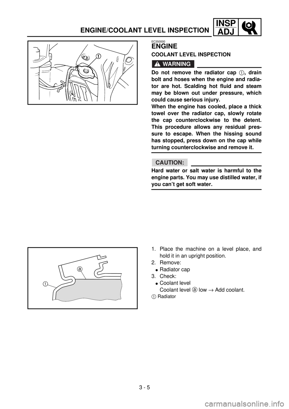
Do not remove the radiator cap
1, drain
bolt and hoses when the engine and radia-
tor are hot. Scalding hot fluid and steam
may be blown out under pressure, which
could cause serious injury.
When the engine has cooled, place a thick
towel over the radiator cap, slowly rotate
the cap counterclockwise to the detent.
This procedure allows any residual pres-
sure to escape. When the hissing sound
has stopped, press down on the cap while
turning counterclockwise and remove it.
CAUTION:
Hard water or salt water is harmful to the
engine parts. You may use distilled water, if
you can’t get soft water.
5PA30010
1. Place the machine on a level place, and
hold it in an upright position.
2. Remove:
lRadiator cap
3. Check:
lCoolant level
Coolant level a low ® Add coolant.
1Radiator
5PA30020
ENGINE/COOLANT LEVEL INSPECTION
Page 158 of 504

3 - 19
INSP
ADJ
FRONT BRAKE PAD INSPECTION AND REPLACEMENT
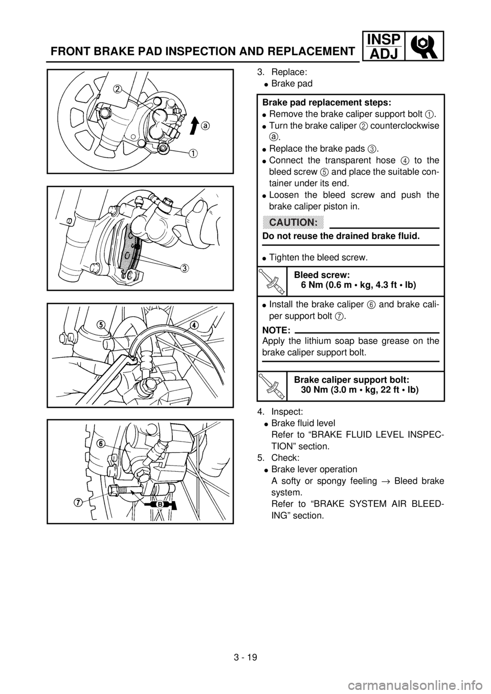
3. Replace:
lBrake pad
4. Inspect:
lBrake fluid level
Refer to “BRAKE FLUID LEVEL INSPEC-
TION” section.
5. Check:
lBrake lever operation
A softy or spongy feeling ® Bleed brake
system.
Refer to “BRAKE SYSTEM AIR BLEED-
ING” section. Brake pad replacement steps:
lRemove the brake caliper support bolt 1.
lTurn the brake caliper 2 counterclockwise
a.
lReplace the brake pads 3.
lConnect the transparent hose 4 to the
bleed screw 5 and place the suitable con-
tainer under its end.
lLoosen the bleed screw and push the
brake caliper piston in.
CAUTION:
Do not reuse the drained brake fluid.
lTighten the bleed screw.
T R..
Bleed screw:
6 Nm (0.6 m • kg, 4.3 ft • lb)
lInstall the brake caliper 6 and brake cali-
per support bolt 7.
NOTE:
Apply the lithium soap base grease on the
brake caliper support bolt.
T R..
Brake caliper support bolt:
30 Nm (3.0 m • kg, 22 ft • lb)
5PA30370
5PA30380
5PA30390
5PA30400
Page 168 of 504

3 - 24
INSP
ADJFRONT FORK INSPECTION/
FRONT FORK OIL SEAL AND DUST SEAL CLEANING
3. Adjust:
lDrive chain slack
Drive chain slack adjustment steps:
lLoosen the axle nut 1 and locknuts 2.
lAdjust chain slack by turning the adjusters 3.
To tighten
® Turn adjuster
3 clockwise.
To loosen
® Turn adjuster
3 counter-
clockwise and push wheel forward.
lTurn each adjuster exactly the same
amount to maintain correct axle alignment.
(There are marks a on each side of chain
puller alignment.)
NOTE:
Turn the adjuster so that the chain is in line
with the sprocket, as viewed from the rear.
CAUTION:
Too small chain slack will overload the
engine and other vital parts; keep the
slack within the specified limits.
lTighten the axle nut while pushing down
the drive chain.
T R..
Axle nut:
110 Nm (11.0 m • kg, 80 ft • lb)
lTighten the locknuts.
5PA30560
EC36C000
FRONT FORK INSPECTION
1. Inspect:
lFront fork smooth action
Operate the front brake and stroke the front
fork.
Unsmooth action/oil leakage ® Repair or
replace.
5PA30570
EC36D001
FRONT FORK OIL SEAL AND DUST SEAL
CLEANING
1. Remove:
lProtector 1
lDust seal 2
NOTE:
Use a thin screw driver, and be careful not to
damage the inner fork tube and dust seal.5PA30580
Page 192 of 504

3 - 36
INSP
ADJ
IGNITION TIMING CHECK
IGNITION TIMING CHECK
1. Remove:
lAir scoop
lSpark plug
lLeft crankcase cover
2. Attach:
lDial gauge 1
lDial gauge stand 2
Dial gauge and stand:
YU-3097/90890-01252
Stand:
YU-12565PA30870
3. Rotate the rotor 1 until the piston reaches
top dead center (TDC). When this hap-
pens, the needle on the dial gauge will stop
and reverse directions even though the
rotor is being turned in the same direction.
4. Set the dial gauge to zero at TDC.
5PA30880
5. From TDC, rotate the rotor clockwise until
the dial gauge indicates that the piston is at
a specified distance from TDC.
Ignition timing (B.T.D.C.):
0.9 mm (0.035 in)
6. Check:
lIgnition timing
Punch mark a on rotor should be aligned
with punch mark b on stator.
Not aligned ® Adjust.
5PA30890
Page 202 of 504

4 - 4
ENGRADIATOR
EC456000
HANDLING NOTE
WARNING
Do not remove the radiator cap when the
engine and radiator are hot. Scalding hot
fluid and steam may be blown out under
pressure, which could cause serious
injury.
When the engine has cooled, open the radi-
ator cap by the following procedure:
Place a thick rag, like a towel, over the radi-
ator cap, slowly rotate the cap counter-
clockwise to the detent. This procedure
allows any residual pressure to escape.
When the hissing sound has stopped,
press down on the cap while turning coun-
terclockwise and remove it.
EC454000
INSPECTION
Radiator
1. Inspect:
lRadiator core 1
Obstruction ® Blow out with compressed
air through rear of the radiator.
Bent fin ® Repair or replace.
5PA40040
EC455000
ASSEMBLY AND INSTALLATION
Radiator
1. Install:
lRadiator breather hose 1
To radiator 2.
5PA40050
2. Install:
lRadiator 1
lBolt (radiator) 2
5PA40060
Page 270 of 504

4 - 38
ENG
2. Install:
lSpring guide 1
NOTE:
Slide the spring guide into the kick shaft, make
sure the groove a in the spring guide fits on
the stopper of the torsion spring.
5PA41120
3. Install:
lKick shaft assembly 1
NOTE:
lApply the transmission oil on the kick shaft.
lApply the lithium soap base grease on the
kick shaft stopper.
lSlide the kick shaft assembly into the crank-
case, make sure the clip 2 and kick shaft
stopper a fit into their home positions b, c.5PA41130
4. Hook:
lTorsion spring 1
NOTE:
Turn the torsion spring clockwise and hook
into the proper hole a in the crankcase.
5PA41140
Kick idle gear
1. Install:
lWasher 1
lKick idle gear 2
lCirclip 3
NOTE:
lApply the transmission oil on the kick idle
gear inner circumference.
lInstall the kick idle gear with its groove a
facing the engine.
5PA41150
KICK SHAFT, SHIFT SHAFT AND PRIMARY DRIVE GEAR
Page 286 of 504

4 - 46
ENG
EC4L3000
REMOVAL POINTS
Rotor
1. Remove:
lNut (rotor) 1
lWasher 2
Use the rotor holding tool 3.
Rotor holding tool:
YU-1235/90890-01235
5PA41390
2. Remove:
lRotor 1
Use the flywheel puller 2.
NOTE:
When installing the flywheel puller, turn it
counterclockwise.
Flywheel puller:
YM-1189/90890-01189
5PA41400
EC4L4000
INSPECTION
EC4L4101
CDI magneto
1. Inspect:
lRotor inner surface a
lStator outer surface b
Damage ® Inspect the crankshaft runout
and crankshaft bearing.
If necessary, replace CDI magneto and/or
stator.
5PA41410
EC4L4200
Woodruff key
1. Inspect:
lWoodruff key 1
Damage ® Replace.
5PA41420
CDI MAGNETO
Page 348 of 504
![YAMAHA YZ85 2002 Owners Manual 5 - 13
CHAS
EC5A3000
REMOVAL POINTS
Brake fluid
1. Remove:
[Front]
lBrake master cylinder cap 1
[Rear]
lReservoir tank cap 1
NOTE:
Do not remove the diaphragm.
ÈFront
ÉRear
È
5PA50290
€
É
5PA5 YAMAHA YZ85 2002 Owners Manual 5 - 13
CHAS
EC5A3000
REMOVAL POINTS
Brake fluid
1. Remove:
[Front]
lBrake master cylinder cap 1
[Rear]
lReservoir tank cap 1
NOTE:
Do not remove the diaphragm.
ÈFront
ÉRear
È
5PA50290
€
É
5PA5](/img/51/54066/w960_54066-347.png)
5 - 13
CHAS
EC5A3000
REMOVAL POINTS
Brake fluid
1. Remove:
[Front]
lBrake master cylinder cap 1
[Rear]
lReservoir tank cap 1
NOTE:
Do not remove the diaphragm.
ÈFront
ÉRear
È
5PA50290
€
É
5PA50300
2. Connect the transparent hose 2 to the
bleed screw 1 and place a suitable con-
tainer under its end.
ÈFront
ÉRear
3. Loosen the bleed screw and drain the
brake fluid while pulling the lever in or
pushing down on the pedal.
CAUTION:
lDo not reuse the drained brake fluid.
lBrake fluid may erode painted surfaces or
plastic parts. Always clean up spilled
fluid immediately.
€
ÈÉ
5PA50310
Front brake caliper
1. Remove:
lBrake caliper 1
NOTE:
Turn the brake caliper counterclockwise and
pull out it from the guide pin 2 on the brake
caliper bracket.
€
5PA50320
FRONT BRAKE AND REAR BRAKE
Page 358 of 504

5 - 18
CHAS
2. Install:
lPin boot 1
On brake caliper 2.
NOTE:
Apply the lithium soap base grease on the pin
boot inner surface.
5PA50500
3. Install:
lBrake caliper bracket 1
lBolt (brake caliper bracket) 2
lBrake pad 3
5PA50510
T R..30 Nm (3.0 m · kg, 22 ft · lb)
4. Install:
lBrake caliper 1
NOTE:
lApply the lithium soap base grease on the
guide pin 2.
lInstall the brake caliper into the guide pin
and turn it clockwise.
5PA50520
5. Install:
lBrake caliper support bolt 1
NOTE:
Apply the lithium soap base grease on the
brake caliper support bolt.
Rear brake caliper
1. Install:
lPad support 1
lBrake pad 2
lPad pin 3
NOTE:
lInstall the brake pad fitted with brake pad
shim 4 on the brake caliper piston side.
lTemporarily tighten the pad pins at this point.
5PA50530
T R..23 Nm (2.3 m · kg, 17 ft · lb)
5PA50540
FRONT BRAKE AND REAR BRAKE
Page 498 of 504

7 - 18
TUNSETTING
Suspension setting
lFront fork
NOTE:
lIf any of the following symptoms is experienced with the standard position as the base, make
resetting by reference to the adjustment procedure given in the same chart.
lBefore any change, set the rear shock absorber sunken length to the standard figure 75 ~ 85 mm
(3.0 ~ 3.3 in).
SymptomSection
Check Adjust
JumpLarge
gapMedium
gapSmall
gap
Stiff over entire range
{{{Compression damping
Oil level (oil amount)
SpringTurn adjuster counterclockwise (about 2 clicks) to
decrease damping.
Decrease oil level by about 5 ~ 10 mm (0.2 ~ 0.4 in).
Replace with soft spring.
Unsmooth movement
over entire range{{{{Outer tube
Inner tube
Under bracket tightening
torqueCheck for any bends, dents, and other noticeable
scars, etc. If any, replace affected parts.
Retighten to specified torque.
Poor initial
movement{Rebound damping
Oil sealTurn adjuster counterclockwise (about 2 clicks) to
decrease damping.
Apply grease in oil seal wall.
Soft over entire range,
bottoming out{{Compression damping
Oil level (oil amount)
SpringTurn adjuster clockwise (about 2 clicks) to increase
damping.
Increase oil level by about 5 ~ 10 mm (0.2 ~ 0.4 in).
Replace with stiff spring.
Stiff toward stroke end{Oil level (oil amount) Decrease oil level by about 5 mm (0.2 in).
Soft toward stroke end,
bottoming out{Oil level (oil amount) Increase oil level by about 5 mm (0.2 in).
Stiff initial movement{{{{Compression dampingTurn adjuster counterclockwise (about 2 clicks) to
decrease damping.
Low front, tending to
lower front posture{{Compression damping
Rebound damping
Balance with rear end
Oil level (oil amount)Turn adjuster clockwise (about 2 clicks) to increase
damping.
Turn adjuster counterclockwise (about 2 clicks) to
decrease damping.
Set sunken length for 80 ~ 85 mm (3.1 ~ 3.3 in) when
one passenger is astride seat (lower rear posture).
Increase oil level by about 5 mm (0.2 in).
“Obtrusive” front, tend-
ing to upper front pos-
ture{{Compression damping
Balance with rear end
Spring
Oil level (oil amount)Turn adjuster counterclockwise (about 2 clicks) to
decrease damping.
Set sunken length for 75 ~ 80 mm (3.0 ~ 3.1 in) when
one passenger is astride seat (upper rear posture).
Replace with soft spring.
Decrease oil level by about 5 ~ 10 mm (0.2 ~ 0.4 in).