YAMAHA YZ85 2022 Owner's Guide
Manufacturer: YAMAHA, Model Year: 2022, Model line: YZ85, Model: YAMAHA YZ85 2022Pages: 90, PDF Size: 2.63 MB
Page 31 of 90
Instrument and control functions
4-3
4
EAU12944
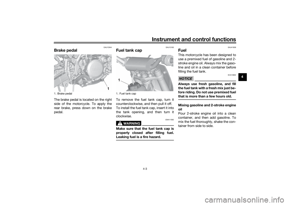
Brake ped alThe brake pedal is located on the right
side of the motorcycle. To apply the
rear brake, press down on the brake
pedal.
EAU13183
Fuel tank capTo remove the fuel tank cap, turn it
counterclockwise, and then pull it off.
To install the fuel tank cap, insert it into
the tank opening, and then turn it
clockwise.
WARNING
EWA11092
Make sure that the fuel tank cap is
properly close d after fillin g fuel.
Leakin g fuel is a fire hazar d.
EAU41838
FuelThis motorcycle has been designed to
use a premixed fuel of gasoline and 2-
stroke engine oil. Always mix the gaso-
line and oil in a clean container before
filling the fuel tank.NOTICE
ECA15602
Always use fresh gasoline, an d fill
the fuel tank with a fresh mix just be-
fore ri din g. Do not use premixe d fuel
that is more than a few hours ol d.Mixing g asoline an d 2-stroke en gine
oil
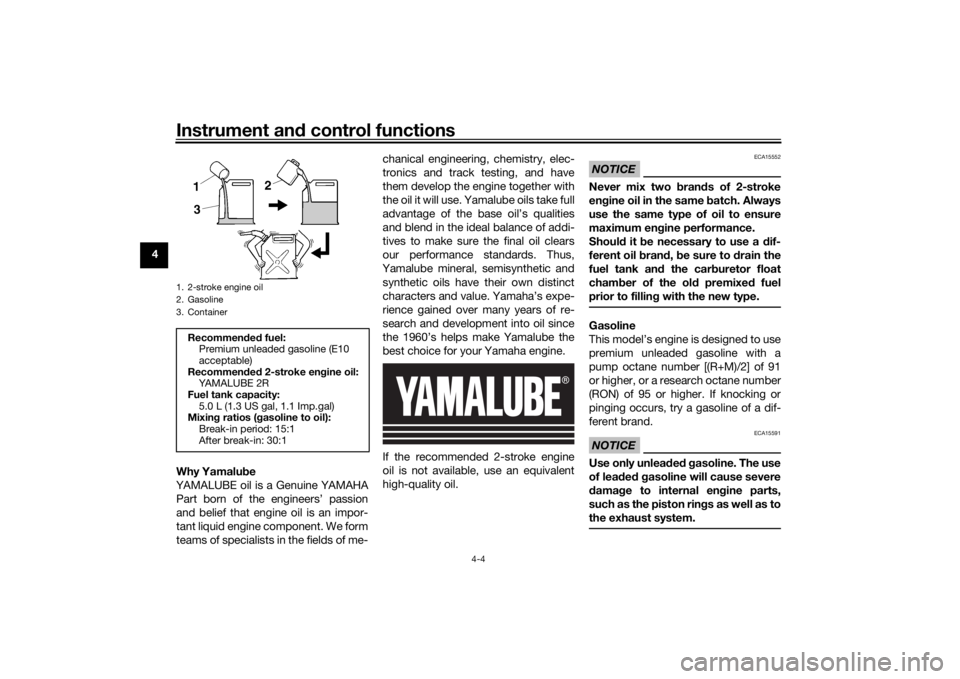
Pour 2-stroke engine oil into a clean
container, and then add gasoline. To
mix the fuel thoroughly, shake the con-
tainer from side to side.
1. Brake pedal
1
1. Fuel tank cap1
UB4B83E0.book Page 3 Thursday, September 9, 2021 8:47 AM
Page 32 of 90
Instrument and control functions
4-4
4
Why Yamalu be
YAMALUBE oil is a Genuine YAMAHA Part born of the engineers’ passion
and belief that engine oil is an impor-
tant liquid engine component. We form
teams of specialists in the fields of me- chanical engineering, chemistry, elec-
tronics and track testing, and have
them develop the engine together with
the oil it will use. Yamalube oils take full
advantage of the base oil’s qualities
and blend in the ideal balance of addi-
tives to make sure the final oil clears
our performance standards. Thus,
Yamalube mineral, semisynthetic and synthetic oils have their own distinct
characters and value. Yamaha’s expe-
rience gained over many years of re-
search and development into oil since
the 1960’s helps make Yamalube the
best choice for your Yamaha engine.
If the recommended 2-stroke engine
oil is not available, use an equivalent
high-quality oil.
NOTICE
ECA15552
Never mix two bran ds of 2-stroke
en gine oil in the same batch. Always
use the same type of oil to ensure
maximum eng ine performance.
Shoul d it b e necessary to use a dif-
ferent oil b rand, b e sure to d rain the
fuel tank an d the car buretor float
cham ber of the ol d premixe d fuel
prior to filling with the new type.Gasoline
This model’s engine is designed to use
premium unleaded gasoline with a
pump octane number [(R+M)/2] of 91
or higher, or a research octane number
(RON) of 95 or higher. If knocking or
pinging occurs, try a gasoline of a dif-
ferent brand.NOTICE
ECA15591
Use only unlea ded g asoline. The use
of lea ded g asoline will cause severe
d amag e to internal en gine parts,
such as the piston rin gs as well as to
the exhaust system.
1. 2-stroke engine oil
2. Gasoline
3. ContainerRecommen ded fuel:
Premium unleaded gasoline (E10
acceptable)
Recommen ded 2-stroke en gine oil:
YA M A L U B E 2 R
Fuel tank capacity: 5.0 L (1.3 US gal, 1.1 Imp.gal)
Mixin g ratios ( gasoline to oil):
Break-in period: 15:1
After break-in: 30:1
UB4B83E0.book Page 4 Thursday, September 9, 2021 8:47 AM
Page 33 of 90
Instrument and control functions
4-5
4
Gasohol
There are two types of gasohol: gaso-
hol containing ethanol and that con-
taining methanol. Gasohol containing
ethanol can be used if the ethanol con-
tent does not exceed 10% (E10). Gas-
ohol containing methanol should not
be used as it can cause engine or fuel
system problems.
Fillin
g the fuel tank
WARNING
EWA10882
Gasoline an d gasoline vapors are
extremely flammab le. To avoid fires
an d explosions an d to re duce the
risk of injury when refueling , follow
these instructions.1. Before refueling, turn off the en- gine and be sure that no one is sit-
ting on the vehicle. Never refuel
while smoking, or while in the vi-
cinity of sparks, open flames, or
other sources of ignition such as
the pilot lights of water heaters
and clothes dryers.
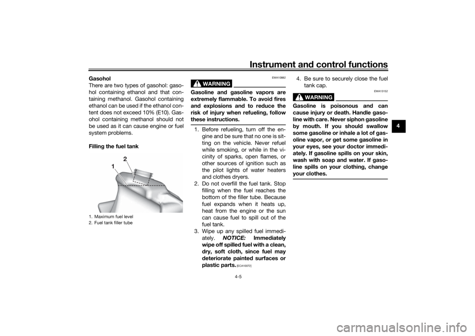
2. Do not overfill the fuel tank. Stop filling when the fuel reaches the
bottom of the filler tube. Because
fuel expands when it heats up,
heat from the engine or the sun
can cause fuel to spill out of the
fuel tank.
3. Wipe up any spilled fuel immedi- ately. NOTICE: Immediately
wipe off spille d fuel with a clean,
d ry, soft cloth, since fuel may
d eteriorate painte d surfaces or
plastic parts.
[ECA10072]
4. Be sure to securely close the fuel tank cap.
WARNING
EWA15152
Gasoline is poisonous an d can
cause injury or death. Han dle gaso-
line with care. Never siphon gasoline
b y mouth. If you shoul d swallow
some gasoline or inhale a lot of g as-
oline vapor, or get some gasoline in
your eyes, see your doctor imme di-
ately. If g asoline spills on your skin,
wash with soap an d water. If gaso-
line spills on your clothin g, chan ge
your clothes.
1. Maximum fuel level
2. Fuel tank filler tube
1
2
UB4B83E0.book Page 5 Thursday, September 9, 2021 8:47 AM
Page 34 of 90
Instrument and control functions
4-6
4
EAU13414
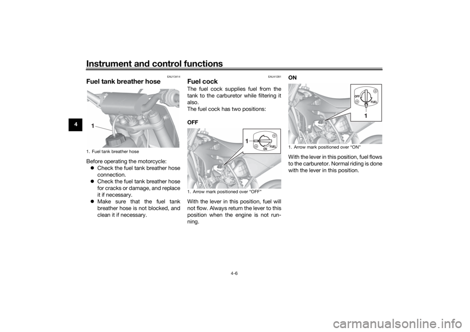
Fuel tank breather hoseBefore operating the motorcycle:
Check the fuel tank breather hose
connection.
Check the fuel tank breather hose
for cracks or damage, and replace
it if necessary.
Make sure that the fuel tank
breather hose is not blocked, and
clean it if necessary.
EAU41281
Fuel cockThe fuel cock supplies fuel from the
tank to the carburetor while filtering it
also.
The fuel cock has two positions:
OFF
With the lever in this position, fuel will
not flow. Always return the lever to this
position when the engine is not run-
ning. ON
With the lever in this position, fuel flows
to the carburetor. Normal riding is done
with the lever in this position.
1. Fuel tank breather hose1
1. Arrow mark positioned over “OFF”
1
1. Arrow mark positioned over “ON”
1
UB4B83E0.book Page 6 Thursday, September 9, 2021 8:47 AM
Page 35 of 90
Instrument and control functions
4-7
4
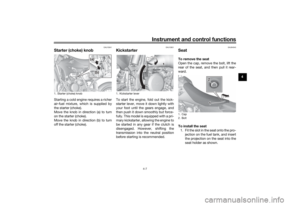
EAU13641
Starter (choke) kno bStarting a cold engine requires a richer
air-fuel mixture, which is supplied by
the starter (choke).
Move the knob in direction (a) to turn
on the starter (choke).
Move the knob in direction (b) to turn
off the starter (choke).
EAU13651
KickstarterTo start the engine, fold out the kick-
starter lever, move it down lightly with
your foot until the gears engage, and
then push it down smoothly but force-
fully. This model is equipped with a pri-
mary kickstarter, allowing the engine to
be started in any gear if the clutch is
disengaged. However, shifting the
transmission into the neutral position
before starting is recommended.
EAU94040
SeatTo remove the seat
Open the cap, remove the bolt, lift the
rear of the seat, and then pull it rear-
ward.
To install the seat
1. Fit the slot in the seat onto the pro- jection on the fuel tank, and insert
the projection on the seat into the
seat holder as shown.
1. Starter (choke) knob
(a) (a)
(b) (b)
(a)
1 1
(b)
1. Kickstarter lever
1 1
1. Cap
2. Bolt
2 21 1
UB4B83E0.book Page 7 Thursday, September 9, 2021 8:47 AM
Page 36 of 90

Instrument and control functions
4-8
4
2. Place the seat in the original posi-tion, tighten the bolt, and then
close the cap.
TIPMake sure that the seat is properly se-
cured before riding.
EAU84383
Adjustin g the front fork
WARNING
EWA10181
Always a djust both fork le gs equally,
otherwise poor han dlin g an d loss of
stab ility may result.This front fork is equipped with re-
bound damping force adjusting screws
and compression damping force ad-
justing screws.NOTICE
ECA10102
To avoi d d amag ing the mechanism,
d o not attempt to turn b eyond the
maximum or minimum setting s.Reboun d d ampin g force
1. Remove the protector. 2. Turn the adjusting screw in direc-
tion (a) to increase the rebound
damping force. Turn the adjusting
screw in direction (b) to decrease
the rebound damping force. To
set the rebound damping force,
turn the adjuster in direction (a)
until it stops, and then count the
clicks in direction (b).
1. Slot
2. Projection
3. Seat holder
1
2
3
2
1. Protector
1
UB4B83E0.book Page 8 Thursday, September 9, 2021 8:47 AM
Page 37 of 90

Instrument and control functions
4-9
4
3. Install the protector.
TIP Install the protector so that the
side with the notch is facing rear-
ward.
When turning the damping force
adjuster in direction (a), the 0 click
position and the 1 click position
may be the same.
When turning the damping force
adjuster in direction (b), it may
click beyond the stated specifica-
tions, however such adjustments
are ineffective and may damage
the suspension.
Compression dampin g force
1. Remove the rubber cap by pulling it out of the front fork leg.
2. Turn the adjusting screw in direc- tion (a) to increase the compres-
sion damping force. Turn the
adjusting screw in direction (b) to
decrease the compression damp-
ing force. To set the compression
damping force, turn the adjuster in
direction (a) until it stops, and then
count the clicks in direction (b).
1. Rebound damping force adjusting screwReboun d d ampin g settin g:
Minimum (soft): 20 click(s) in direction (b)
Standard: 7 click(s) in direction (b)
Maximum (hard):
1 click(s) in direction (b)
1 1
(b) (b)
(a) (a) (b)
(a)
(b) (b)
(a) (a) (b)
(a)
1. Notch
1
1. Rubber cap
2. Compression damping force adjusting screw
2
1
(a)
(b)
UB4B83E0.book Page 9 Thursday, September 9, 2021 8:47 AM
Page 38 of 90

Instrument and control functions
4-10
4
3. Install the rubber cap.
TIPWhen turning the damping force
adjuster in direction (a), the 0 click
position and the 1 click position
may be the same.
When turning the damping force
adjuster in direction (b), it may
click beyond the stated specifica-
tions, however such adjustments
are ineffective and may damage
the suspension.
EAU84390
Front fork blee din gWhen riding in extremely rough condi-
tions, the air temperature and pressure
in the front fork will rise. This will in-
crease the spring preload and harden
the front suspension. If this occurs,
bleed the air from each front fork leg.
WARNING
EWA10201
Always blee d b oth fork le gs, other-
wise poor han dlin g an d loss of sta-
b ility may result.To bleed the front fork legs1. Remove the protector.
2. Place the motorcycle on a suitable
stand. (See page 7-26.) 3. Make sure the front wheel is off
the ground and the area near the
bleed screws is clean.
4. Remove the bleed screws.
5. Wait a few seconds, and then in- stall the bleed screws.
6. Install the protector.
Compression dampin g settin g:
Minimum (soft):
20 click(s) in direction (b)
Standard:
10 (YZ85LW, YZ85LWN)
12 (YZ85, YZ85N) click(s) in di-
rection (b)
Maximum (hard): 1 click(s) in direction (b)
1. Protector
1
1. Bleed screw
1
UB4B83E0.book Page 10 Thursday, September 9, 2021 8:47 AM
Page 39 of 90

Instrument and control functions
4-11
4
EAU4133A
A djustin g the shock a bsor ber
assemb lyThis shock absorber assembly is
equipped with a spring preload adjust-
ing nut, a rebound damping force ad-
justing screw and a compression
damping force adjusting screw.NOTICE
ECA10102
To avoid d amag ing the mechanism,
d o not attempt to turn b eyond the
maximum or minimum settin gs.Sprin g preloa d
Adjust the spring preload as follows. 1. Loosen the clamp bolts, and then remove the air filter joint.
2. Loosen the locknut.
3. Turn the adjusting nut in direction(a) to increase the spring preload.
Turn the adjusting nut in direction
(b) to decrease the spring preload.
A special wrench can be ob-
tained at a Yamaha dealer to
make this adjustment.
The spring preload setting is
determined by measuring
distance A, shown in the illus-
tration. The longer distance A
is, the lower the spring pre-
load; the shorter distance A
is, the higher the spring pre-
load. With each complete
turn of the adjusting nut, dis-
tance A is changed by 1.5
mm (0.06 in).
1. Clamp bolt
2. Air filter joint
1. Clamp bolt
1 1
2 21 1 1
1. Locknut
2. Spring preload adjusting nut
1 2 1
(a) (a) (b) (b)
(a) (b)
2
UB4B83E0.book Page 11 Thursday, September 9, 2021 8:47 AM
Page 40 of 90

Instrument and control functions
4-12
4
4. Tighten the locknut to the speci-fied torque. NOTICE: Always
ti g hten the locknut ag ainst the
a d justin g nut, and then tighten
the locknut to the specified
torque.
[ECA10122]
5. Install the air filter joint in its origi- nal position, and then tighten the
clamp bolts.TIPAlign the projection on the air filter joint
with the projection on the frame guide.Reboun d d ampin g force
Turn the adjusting screw in direction (a)
to increase the rebound damping
force. Turn the adjusting screw in direction (b)
to decrease the rebound damping
force.
To set the rebound damping force, turn
the adjuster in direction (a) until it
stops, and then count the clicks in di-
rection (b).
1. Distance ASprin
g preloa d:
Minimum (soft): Distance A = 218.5 mm (8.60 in)
Standard: Distance A = 210.0 mm (8.27 in)
(YZ85LW, YZ85LWN)
215.0 mm (8.46 in) (YZ85,
YZ85N)
Maximum (hard):
Distance A = 202.0 mm (7.95 in)
1
Tightenin g torque:
Locknut:
30 N·m (3.0 kgf·m, 22 lb·ft)1. Frame guide
2. Air filter joint
3. Projection
2 2
1 1
3 3
1. Rebound damping force adjusting screwRe boun d d ampin g setting :
Minimum (soft): 20 click(s) in direction (b)
Standard: 10 (YZ85LW, YZ85LWN)
6 (YZ85, YZ85N) click(s) in direc-
tion (b)
Maximum (hard): 1 click(s) in direction (b)
1 1(a) (a)
(b) (b) (a)
(b)
UB4B83E0.book Page 12 Thursday, September 9, 2021 8:47 AM