Front YAMAHA YZF-R1 2014 User Guide
[x] Cancel search | Manufacturer: YAMAHA, Model Year: 2014, Model line: YZF-R1, Model: YAMAHA YZF-R1 2014Pages: 114, PDF Size: 2.87 MB
Page 38 of 114
INSTRUMENT AND CONTROL FUNCTIONS
3-23
3
“TCS” modes 2 through 6 provide
for more traction control system
assist. Mode 6 provides the most
traction control system assist.
“TCS OFF” mode turns the trac-
tion control system off. The sys-
tem may also be automatically
disabled in some riding conditions
(see “Resetting” on page 3-23).
When the key is turned to “ON”, the
traction control system is enabled and
the last mode selected displays in the
multi-function meter.
All traction control system modes can
be selected when the key is in the “ON”
position. Modes 1 through 6 can also
be selected when the vehicle is mov-
ing, however the throttle grip must be
completely closed. The traction control
system cannot be turned on or off
while the vehicle is moving.
NOTICE
ECA16801
Use only the specified tires. (See
pa ge 6-18.) Usin g different size d
tires will prevent the traction control
system from controllin g tire rotation
accurately.
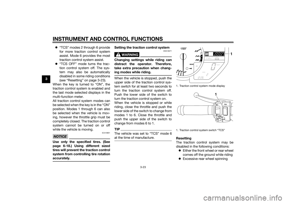
Setting the traction control system
WARNING
EWA16071
Changin g settin gs while ri din g can
d istract the operator. Therefore,
take extra precaution when chan g-
in g mo des while rid ing.When the vehicle is stopped, push the
upper side of the traction control sys-
tem switch for at least two seconds to
turn the traction control system off.
Push the lower side of the switch to
turn the traction control system on.
When the vehicle is stopped or while
riding, close the throttle and push the
lower side of the switch to change from
modes 1 to 6. Close the throttle and
push the upper side of the switch to
change from modes 6 to 1.TIPThe vehicle was set to “TCS” mode 6
at the time of manufacture.
Resettin g
The traction control system may be
disabled in the following conditions: Either the front wheel or rear wheel
comes off the ground while riding
Excessive rear wheel spinning1. Traction control system mode display
1. Traction control system switch “TCS”
1
1
U2SGE0E0.book Page 23 Wednesday, June 12, 2013 1:15 PM
Page 39 of 114
INSTRUMENT AND CONTROL FUNCTIONS
3-24
3
If the traction control system has been
disabled, both the traction control sys-
tem indicator/warning light and the en-
gine trouble warning light come on.
To reset the traction control system:
Turn the key to “OFF”. Wait at least one
second, then turn the key back to
“ON”. The traction control system indi-
cator/warning light should go off and
the system will be enabled. The engine
trouble warning light should go off after
the motorcycle reaches at least 20
km/h (12 mi/h). If the traction control
system indicator/warning light and/or
engine trouble warning light still remain
on after resetting, the motorcycle may
still be ridden; however, have a
Yamaha dealer check the motorcycle as soon as possible.NOTICE
ECA17732
Keep any type of mag nets (in-
clu din g ma gnetic pick-up tools,
ma gnetic screw drivers, etc.)
away from the front wheel sen-
sor or rotor; otherwise, the sen-
sor or rotor may be damag ed , resultin
g in improper perfor-
mance of the traction control
system.
Be careful not to d amage the
sensor or rotor.
EAU13075
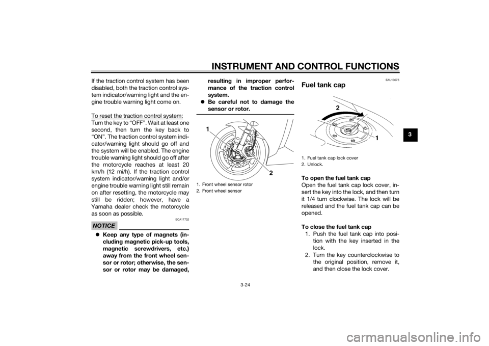
Fuel tank capTo open the fuel tank cap
Open the fuel tank cap lock cover, in-
sert the key into the lock, and then turn
it 1/4 turn clockwise. The lock will be
released and the fuel tank cap can be
opened.
To close the fuel tank cap 1. Push the fuel tank cap into posi- tion with the key inserted in the
lock.
2. Turn the key counterclockwise to the original position, remove it,
and then close the lock cover.
1. Front wheel sensor rotor
2. Front wheel sensor
2
1
1. Fuel tank cap lock cover
2. Unlock.
U2SGE0E0.book Page 24 Wednesday, June 12, 2013 1:15 PM
Page 42 of 114
INSTRUMENT AND CONTROL FUNCTIONS
3-27
3
EAU13434
Catalytic converterThis model is equipped with a catalytic
converter in the exhaust system.
WARNING
EWA10863
The exhaust system is hot after op-
eration. To prevent a fire hazard or
b urns:
Do not park the vehicle near
possi ble fire hazard s such as
g rass or other materials that
easily burn.
Park the vehicle in a place
where ped estrians or chil dren
are not likely to touch the hot
exhaust system.
Make sure that the exhaust sys-
tem has cooled down before
d oin g any maintenance work.
Do not allow the en gine to i dle
more than a few minutes. Lon g
i d lin g can cause a b uild-up of
heat.
NOTICE
ECA10702
Use only unlea ded g asoline. The use
of lead ed g asoline will cause unre-
pairab le dama ge to the catalytic
converter.
EAU47272
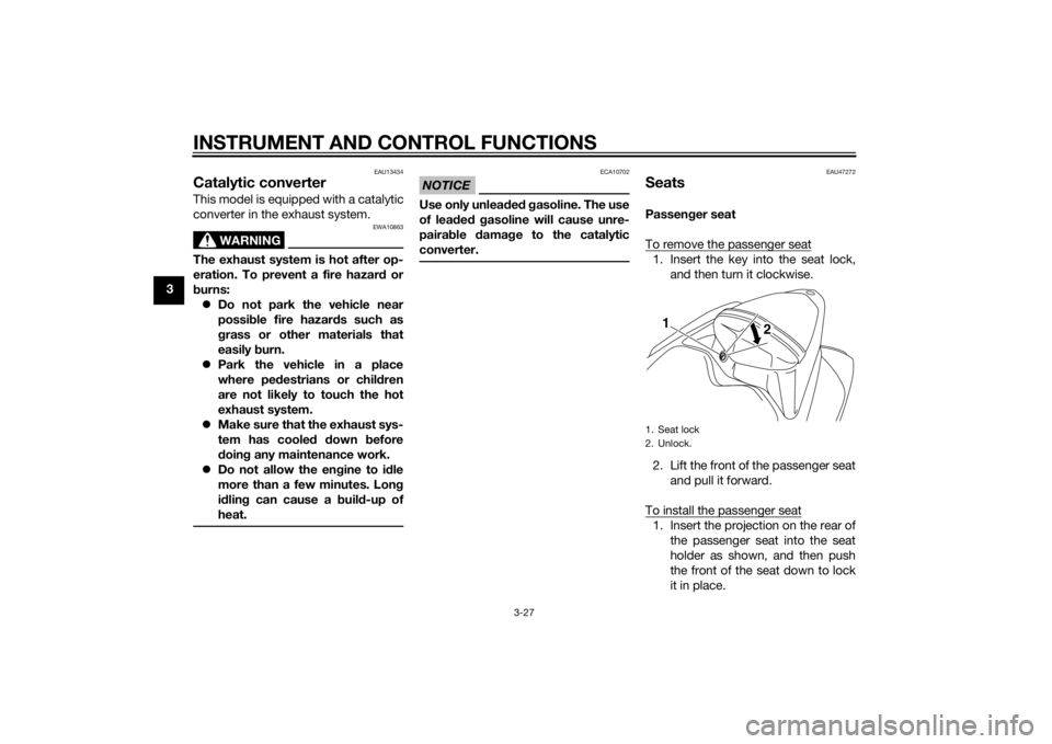
SeatsPassen ger seat
To remove the passenger seat1. Insert the key into the seat lock, and then turn it clockwise.
2. Lift the front of the passenger seat and pull it forward.
To install the passenger seat1. Insert the projection on the rear of the passenger seat into the seat
holder as shown, and then push
the front of the seat down to lock
it in place.1. Seat lock
2. Unlock.
1 2
U2SGE0E0.book Page 27 Wednesday, June 12, 2013 1:15 PM
Page 46 of 114
INSTRUMENT AND CONTROL FUNCTIONS
3-31
3
EAU47622
Adjustin g the front fork
WARNING
EWA14671
Always a djust the sprin g preloa d on
b oth fork le gs equally, otherwise
poor han dlin g an d loss of sta bility
may result.Each front fork leg is equipped with a
spring preload adjusting bolt, the right
front fork leg is equipped with a re-
bound damping force adjusting screw
and the left front fork leg with a com-
pression damping force adjusting
screw.NOTICE
ECA10102
To avoi d d amag ing the mechanism,
d o not attempt to turn b eyond the
maximum or minimum setting s.Spring preloa d
To increase the spring preload and
thereby harden the suspension, turn
the adjusting bolt on each fork leg in di-
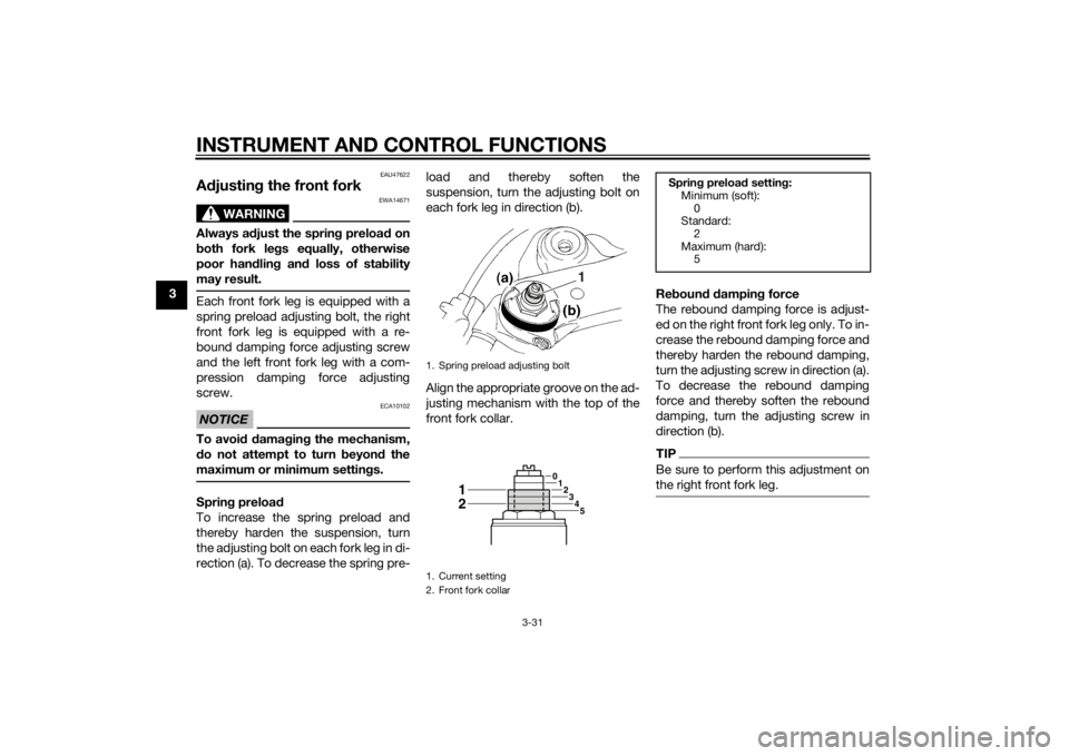
rection (a). To decrease the spring pre- load and thereby soften the
suspension, turn the adjusting bolt on
each fork leg in direction (b).
Align the appropriate groove on the ad-
justing mechanism with the top of the
front fork collar.
Re
boun d d ampin g force
The rebound damping force is adjust-
ed on the right front fork leg only. To in-
crease the rebound damping force and
thereby harden the rebound damping,
turn the adjusting screw in direction (a).
To decrease the rebound damping
force and thereby soften the rebound
damping, turn the adjusting screw in
direction (b).
TIPBe sure to perform this adjustment on
the right front fork leg.
1. Spring preload adjusting bolt
1. Current setting
2. Front fork collar
1
0 123
45
12
Sprin g preloa d setting :
Minimum (soft):
0
Standard:
2
Maximum (hard): 5
U2SGE0E0.book Page 31 Wednesday, June 12, 2013 1:15 PM
Page 47 of 114
INSTRUMENT AND CONTROL FUNCTIONS
3-32
3
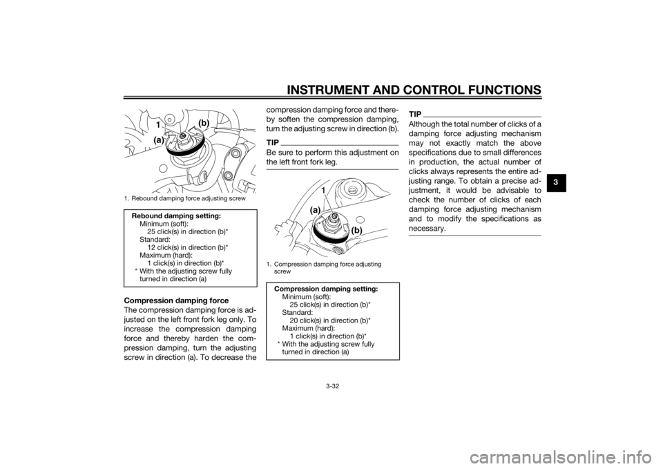
Compression dampin g force
The compression damping force is ad-
justed on the left front fork leg only. To
increase the compression damping
force and thereby harden the com-
pression damping, turn the adjusting
screw in direction (a). To decrease the compression damping force and there-
by soften the compression damping,
turn the adjusting screw in direction (b).
TIPBe sure to perform this adjustment on
the left front fork leg.
TIPAlthough the total number of clicks of a
damping force adjusting mechanism
may not exactly match the above
specifications due to small differences
in production, the actual number of
clicks always represents the entire ad-
justing range. To obtain a precise ad-
justment, it would be advisable to
check the number of clicks of each
damping force adjusting mechanism
and to modify the specifications as
necessary.
1. Rebound damping force adjusting screwRe
boun d d ampin g settin g:
Minimum (soft): 25 click(s) in direction (b)*
Standard: 12 click(s) in direction (b)*
Maximum (hard):
1 click(s) in direction (b)*
* With the adjusting screw fully turned in direction (a)
(b)
1
(a)
1. Compression damping force adjusting screw
Compression dampin g setting :
Minimum (soft): 25 click(s) in direction (b)*
Standard: 20 click(s) in direction (b)*
Maximum (hard):
1 click(s) in direction (b)*
* With the adjusting screw fully turned in direction (a)
1
U2SGE0E0.book Page 32 Wednesday, June 12, 2013 1:15 PM
Page 53 of 114
FOR YOUR SAFETY – PRE-OPERATION CHECKS
4-1
4
EAU15598
Inspect your vehicle each time you use it to make sure the vehicle is in safe operating condition. Always follow the inspection
and maintenance procedures and schedules described in the Owner’s Manual.
WARNING
EWA11152
Failure to inspect or maintain the vehicle properly increases the possibility of an acci dent or equipment damag e.
Do not operate the vehicle if you fin d any pro blem. If a pro blem cannot be corrected b y the proce dures provi ded in
this manual, have the vehicle inspecte d b y a Yamaha dealer.Before using this vehicle, check the following points:
ITEM CHECKS PAGE
Fuel • Check fuel level in fuel tank.
• Refuel if necessary.
• Check fuel line for leakage.
• Check fuel tank breather hose and overflow hose for obstructions, cracks or
damage, and check hose connections. 3-25, 3-26
En gine oil • Check oil level in engine.
• If necessary, add recommended oil to specified level.
• Check vehicle for oil leakage. 6-11
Coolant • Check coolant level in reservoir.
• If necessary, add recommended coolant to specified level.
• Check cooling system for leakage. 6-14
Front brake • Check operation.
• If soft or spongy, have Yamaha dealer bleed hydraulic system.
• Check brake pads for wear.
• Replace if necessary.
• Check fluid level in reservoir.
• If necessary, add specified brake fluid to specified level.
• Check hydraulic system for leakage. 6-23, 6-24
U2SGE0E0.book Page 1 Wednesday, June 12, 2013 1:15 PM
Page 63 of 114

PERIODIC MAINTENANCE AND ADJUSTMENT
6-4
6
EAU1770G
General maintenance and lu brication chartNO. ITEM CHECK OR MAINTENANCE JOB ODOMETER READING
ANNUAL
CHECK
1000 km
(600 mi) 10000 km
(6000 mi) 20000 km
(12000 mi) 30000 km
(18000 mi) 40000 km
(24000 mi)
1 *Air filter element •Replace. √
2Clutch • Check operation.
•Adjust.
√√√√√
3 *Front brake • Check operation, fluid level and
vehicle for fluid leakage. √√√√√√
• Replace brake pads. Whenever worn to the limit
4 *Rear brake • Check operation, fluid level and
vehicle for fluid leakage. √√√√√√
• Replace brake pads. Whenever worn to the limit
5 *Brake hoses • Check for cracks or damage.
• Check for correct routing and
clamping. √√√√√
• Replace. Every 4 years
6 *Brake flui d • Replace. Every 2 years
7 *Wheels • Check runout and for damage. √√√√
8 *Tires • Check tread depth and for dam-
age.
• Replace if necessary.
• Check air pressure.
• Correct if necessary. √√√√√
9 *Wheel bearin gs • Check bearing for looseness or
damage. √√√√
U2SGE0E0.book Page 4 Wednesday, June 12, 2013 1:15 PM
Page 65 of 114

PERIODIC MAINTENANCE AND ADJUSTMENT
6-6
6
19 Sidestan d • Check operation.
• Lubricate with lithium-soap-
based grease. √√√√√
20 *Sidestan d switch • Check operation. √√√√√√
21 *Front fork • Check operation and for oil leak-
age. √√√√
22 *Shock a
bsor ber as-
sem bly • Check operation and shock ab-
sorber for oil leakage. √√√√
23 *Rear suspension re-
lay arm an
d con-
nectin g arm
pivotin g points • Check operation.
√√√√
24 En gine oil • Change.
• Check oil level and vehicle for oil
leakage. √√√√√√
25 En
gine oil filter car-
tri dg e •Replace.
√√√
26 *Coolin g system • Check coolant level and vehicle
for coolant leakage. √√√√√
• Change coolant. Every 3 years
27 *Front an
d rear
b rake switches • Check operation.
√√√√√√
28 Movin
g parts an d
ca bles • Lubricate.
√√√√√
NO. ITEM CHECK OR MAINTENANCE JOB
ODOMETER READING
ANNUAL
CHECK
1000 km
(600 mi) 10000 km
(6000 mi) 20000 k
m
(12000 mi) 30000 km
(18000 mi) 40000 km
(24000 mi)
U2SGE0E0.book Page 6 Wednesday, June 12, 2013 1:15 PM
Page 78 of 114
PERIODIC MAINTENANCE AND ADJUSTMENT
6-19
6wei
ght of ri der, passen ger, car-
g o, an d accessories approve d
for this mo del.
WARNING
EWA10512
Never overloa d your vehicle. Opera-
tion of an overloa ded vehicle coul d
cause an acci dent.
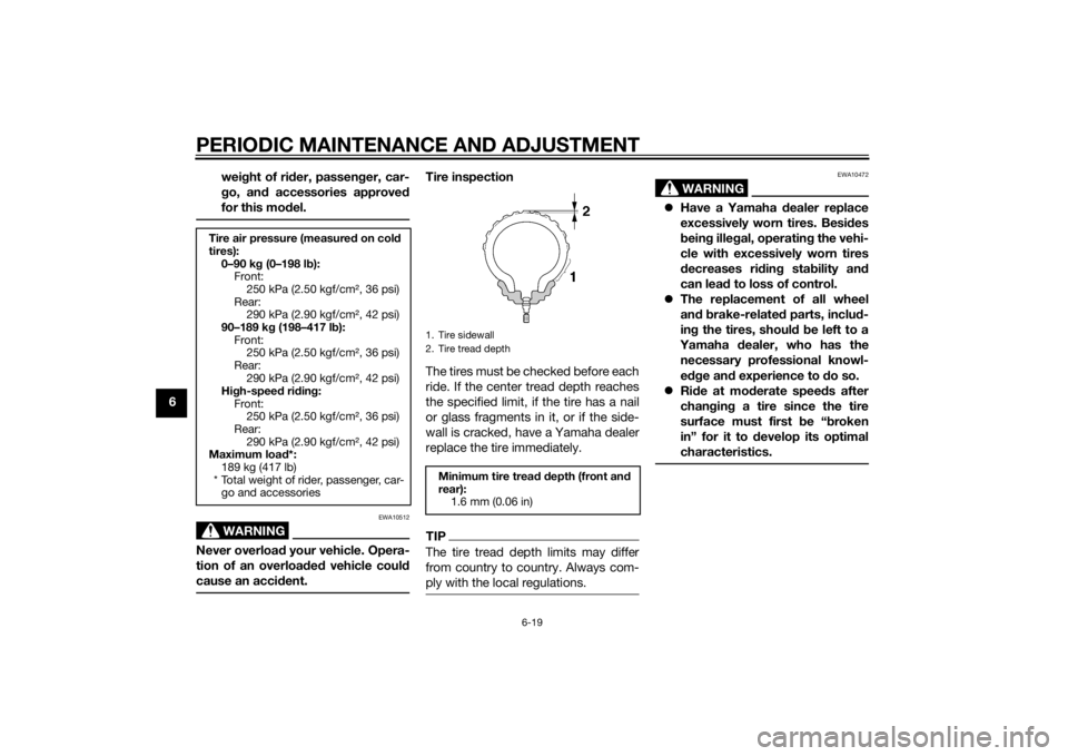
Tire inspection
The tires must be checked before each
ride. If the center tread depth reaches
the specified limit, if the tire has a nail
or glass fragments in it, or if the side-
wall is cracked, have a Yamaha dealer
replace the tire immediately.TIPThe tire tread depth limits may differ
from country to country. Always com-
ply with the local regulations.
WARNING
EWA10472
Have a Yamaha dealer replace
excessively worn tires. Besi des
b ein g ille gal, operatin g the vehi-
cle with excessively worn tires
d ecreases rid ing sta bility an d
can lead to loss of control.
The replacement of all wheel
and b rake-relate d parts, inclu d-
in g the tires, shoul d b e left to a
Yamaha dealer, who has the
necessary professional knowl-
e dge an d experience to do so.
Ride at mo derate speed s after
chan gin g a tire since the tire
surface must first be “ broken
in” for it to develop its optimal
characteristics.
Tire air pressure (measure d on col d
tires): 0–90 k g (0–198 l b):
Front:
250 kPa (2.50 kgf/cm², 36 psi)
Rear: 290 kPa (2.90 kgf/cm², 42 psi)
90–189 k g (198–417 l b):
Front: 250 kPa (2.50 kgf/cm², 36 psi)
Rear: 290 kPa (2.90 kgf/cm², 42 psi)
Hi gh-spee d ri din g:
Front: 250 kPa (2.50 kgf/cm², 36 psi)
Rear:
290 kPa (2.90 kgf/cm², 42 psi)
Maximum loa d*:
189 kg (417 lb)
* Total weight of rider, passenger, car- go and accessories
1. Tire sidewall
2. Tire tread depthMinimum tire trea d d epth (front an d
rear): 1.6 mm (0.06 in)
U2SGE0E0.book Page 19 Wednesday, June 12, 2013 1:15 PM
Page 79 of 114
PERIODIC MAINTENANCE AND ADJUSTMENT
6-20
6
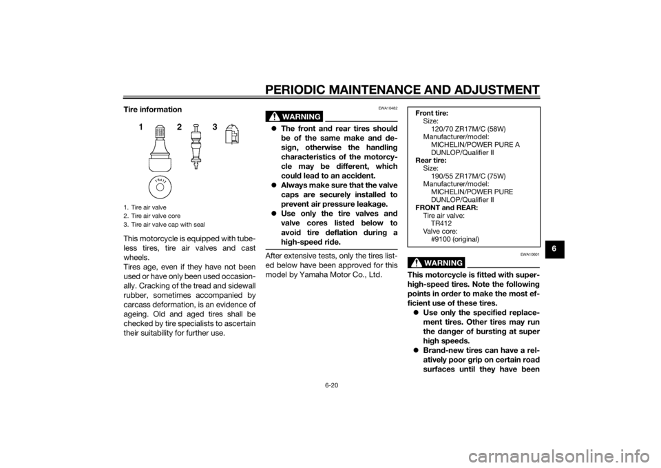
Tire information
This motorcycle is equipped with tube-
less tires, tire air valves and cast
wheels.
Tires age, even if they have not been
used or have only been used occasion-
ally. Cracking of the tread and sidewall
rubber, sometimes accompanied by
carcass deformation, is an evidence of
ageing. Old and aged tires shall be
checked by tire specialists to ascertain
their suitability for further use.
WARNING
EWA10482
The front an d rear tires shoul d
b e of the same make an d d e-
si gn, otherwise the han dlin g
characteristics of the motorcy-
cle may b e different, which
coul d lea d to an acci dent.
Always make sure that the valve
caps are securely installe d to
prevent air pressure leaka ge.
Use only the tire valves an d
valve cores liste d below to
avoi d tire deflation during a
hi gh-spee d ri de.After extensive tests, only the tires list-
ed below have been approved for this
model by Yamaha Motor Co., Ltd.
WARNING
EWA10601
This motorcycle is fitte d with super-
hi gh-spee d tires. Note the followin g
points in or der to make the most ef-
ficient use of these tires. Use only the specified replace-
ment tires. Other tires may run
the dan ger of bursting at super
hi gh spee ds.
Bran d-new tires can have a rel-
atively poor grip on certain roa d
surfaces until they have been
1. Tire air valve
2. Tire air valve core
3. Tire air valve cap with seal
Front tire:
Size:
120/70 ZR17M/C (58W)
Manufacturer/model:
MICHELIN/POWER PURE A
DUNLOP/Qualifier II
Rear tire:
Size: 190/55 ZR17M/C (75W)
Manufacturer/model:
MICHELIN/POWER PURE
DUNLOP/Qualifier II
FRONT and REAR:
Tire air valve: TR412
Valve core:
#9100 (original)
U2SGE0E0.book Page 20 Wednesday, June 12, 2013 1:15 PM