engine YAMAHA YZF-R1 2022 Owners Manual
[x] Cancel search | Manufacturer: YAMAHA, Model Year: 2022, Model line: YZF-R1, Model: YAMAHA YZF-R1 2022Pages: 136, PDF Size: 6.01 MB
Page 8 of 136
Table of contentsSafety information ............................ 1-1
Description ....................................... 2-1
Left view ......................................... 2-1
Right view ....................................... 2-2
Controls and instruments ............... 2-3
Special features .............................. 3-1
YRC (Yamaha Ride Control) ........... 3-1
Glossary ......................................... 3-5
YRC functions visual guide ............ 3-6
Instrument an d control functions ... 4-1
Immobilizer system......................... 4-1
Main switch/steering lock............... 4-2
Handlebar switches ........................ 4-3
Indicator lights and warning
lights............................................ 4-6
Display ............................................ 4-9
MENU screen ............................... 4-15
Clutch lever .................................. 4-32
Shift pedal .................................... 4-32
Brake lever.................................... 4-33
Brake pedal .................................. 4-33
Brake control system (BC)............ 4-34
Fuel tank cap ................................ 4-35
Fuel ............................................... 4-36
Fuel tank overflow hose ............... 4-37
Catalytic converter ....................... 4-38
Seats ............................................ 4-38
CCU (for equipped models).......... 4-40 Seat cover (for equipped
models) ...................................... 4-41
Document storage ........................ 4-41
Rear view mirrors .......................... 4-42
Adjusting the front fork ................. 4-42
Adjusting the shock absorber assembly.................................... 4-45
EXUP system ................................ 4-49
Auxiliary DC connector ................. 4-49
Sidestand ...................................... 4-49
Ignition circuit cut-off system ....... 4-50
For your safety – pre-operation
checks ............................................... 5-1
Operation an d important ri din g
points ................................................. 6-1
Engine break-in ............................... 6-1
Starting the engine .......................... 6-2
Shifting ............................................ 6-3
Tips for reducing fuel consumption ................................ 6-4
Parking ............................................ 6-4
Perio dic maintenance an d
a d justment ........................................ 7-1
Tool kit ............................................ 7-2
Periodic maintenance charts .......... 7-3
Periodic maintenance chart for the emission control system .............. 7-3 General maintenance and
lubrication chart .......................... 7-5
Cowlings and panels ...................... 7-9
Checking the spark plugs ............. 7-12
Canister ........................................ 7-13
Engine oil and oil filter cartridge ... 7-13
Why Yamalube.............................. 7-16
Coolant ......................................... 7-16
Air filter element ............................ 7-18
Checking the engine idling speed ........................................ 7-18
Valve clearance............................. 7-18
Tires .............................................. 7-19
Cast magnesium wheels .............. 7-21
Adjusting the clutch lever free play ............................................ 7-22
Checking the brake lever free
play ............................................ 7-23
Brake light switches ..................... 7-24
Checking the front and rear brake pads ................................ 7-24
Checking the brake fluid level ...... 7-25
Changing the brake fluid .............. 7-26
Drive chain slack........................... 7-26
Cleaning and lubricating the drive chain ................................. 7-28
Checking and lubricating the cables ........................................ 7-28
Checking and lubricating the
throttle grip ................................ 7-29UB3LE1E0.book Page 1 Tuesday, August 10, 2021 2:28 PM
Page 11 of 136
Safety information
1-2
1
Many accidents involve inexperi-
enced operators. In fact, many op-
erators who have been involved in
accidents do not even have a cur-
rent motorcycle license.
• Make sure that you are qualified and that you only lend your mo-
torcycle to other qualified oper-
ators.
• Know your skills and limits. Staying within your limits may
help you to avoid an accident.
• We recommend that you prac- tice riding your motorcycle
where there is no traffic until you
have become thoroughly famil-
iar with the motorcycle and all of
its controls.
Many accidents have been
caused by error of the motorcycle
operator. A typical error made by
the operator is veering wide on a
turn due to excessive speed or un-
dercornering (insufficient lean an-
gle for the speed).
• Always obey the speed limit and never travel faster than warrant-
ed by road and traffic condi-
tions. • Always signal before turning or
changing lanes. Make sure that
other motorists can see you.
The posture of the operator and
passenger is important for proper
control.
• The operator should keep both hands on the handlebar and
both feet on the operator foot-
rests during operation to main-
tain control of the motorcycle.
• The passenger should always hold onto the operator, the seat
strap or grab bar, if equipped,
with both hands and keep both
feet on the passenger footrests.
Never carry a passenger unless
he or she can firmly place both
feet on the passenger footrests.
Never ride under the influence of
alcohol or other drugs.
This motorcycle is designed for
on-road use only. It is not suitable
for off-road use. Protective Apparel
The majority of fatalities from motorcy-
cle accidents are the result of head in-
juries. The use of a safety helmet is the
single most critical factor in the pre-
vention or reduction of head injuries.
Always wear an approved helmet.
Wear a face shield or goggles.
Wind in your unprotected eyes
could contribute to an impairment
of vision that could delay seeing a
hazard.
The use of a jacket, heavy boots,
trousers, gloves, etc., is effective
in preventing or reducing abra-
sions or lacerations.
Never wear loose-fitting clothes,
otherwise they could catch on the
control levers, footrests, or wheels
and cause injury or an accident.
Always wear protective clothing
that covers your legs, ankles, and
feet. The engine or exhaust sys-
tem become very hot during or af-
ter operation and can cause
burns.
A passenger should also observe
the above precautions.
UB3LE1E0.book Page 2 Tuesday, August 10, 2021 2:28 PM
Page 12 of 136
Safety information
1-3
1Avoi
d Car bon Monoxi de Poisonin g
All engine exhaust contains carbon
monoxide, a deadly gas. Breathing
carbon monoxide can cause head-
aches, dizziness, drowsiness, nausea,
confusion, and eventually death.
Carbon Monoxide is a colorless, odor-
less, tasteless gas which may be pres-
ent even if you do not see or smell any
engine exhaust. Deadly levels of car-
bon monoxide can collect rapidly and
you can quickly be overcome and un-
able to save yourself. Also, deadly lev-
els of carbon monoxide can linger for
hours or days in enclosed or poorly
ventilated areas. If you experience any
symptoms of carbon monoxide poi-
soning, leave the area immediately, get
fresh air, and SEEK MEDICAL TREAT-
MENT. Do not run engine indoors. Even if
you try to ventilate engine exhaust
with fans or open windows and
doors, carbon monoxide can rap-
idly reach dangerous levels.
Do not run engine in poorly venti-
lated or partially enclosed areas
such as barns, garages, or car-
ports.
Do not run engine outdoors where
engine exhaust can be drawn into
a building through openings such
as windows and doors.
Loa din g
Adding accessories or cargo to your
motorcycle can adversely affect stabil-
ity and handling if the weight distribu-
tion of the motorcycle is changed. To
avoid the possibility of an accident, use
extreme caution when adding cargo or
accessories to your motorcycle. Use
extra care when riding a motorcycle
that has added cargo or accessories.
Here, along with the information about
accessories below, are some general
guidelines to follow if loading cargo to
your motorcycle:
The total weight of the operator, pas-
senger, accessories and cargo must
not exceed the maximum load limit.
Operation of an overloa ded vehicle
coul d cause an acci dent. When loading within this weight limit,
keep the following in mind:
Cargo and accessory weight
should be kept as low and close to
the motorcycle as possible. Se-
curely pack your heaviest items as
close to the center of the vehicle
as possible and make sure to dis-
tribute the weight as evenly as
possible on both sides of the mo-
torcycle to minimize imbalance or
instability.
Shifting weights can create a sud-
den imbalance. Make sure that
accessories and cargo are se-
curely attached to the motorcycle
before riding. Check accessory
mounts and cargo restraints fre-
quently.
• Properly adjust the suspension for your load (suspension-ad-
justable models only), and
check the condition and pres-
sure of your tires.
• Never attach any large or heavy items to the handlebar, front
fork, or front fender. These
items, including such cargo as
sleeping bags, duffel bags, or
Maximum loa d:
185 kg (408 lb)
UB3LE1E0.book Page 3 Tuesday, August 10, 2021 2:28 PM
Page 14 of 136
Safety information
1-5
1operator and may limit control
ability, therefore, such accesso-
ries are not recommended.
Use caution when adding electri-
cal accessories. If electrical ac-
cessories exceed the capacity of
the motorcycle’s electrical sys-
tem, an electric failure could re-
sult, which could cause a
dangerous loss of lights or engine
power.
Aftermarket Tires an d Rims
The tires and rims that came with your
motorcycle were designed to match
the performance capabilities and to
provide the best combination of han-
dling, braking, and comfort. Other
tires, rims, sizes, and combinations
may not be appropriate. See page 7-19
for tire specifications and for informa-
tion on servicing and replacing your
tires.
Transportin g the Motorcycle
Be sure to observe following instruc-
tions before transporting the motorcy-
cle in another vehicle.
Remove all loose items from the
motorcycle.
Check that the fuel cock (if
equipped) is in the off position and
that there are no fuel leaks.
Shift the transmission into gear
(for models with a manual trans-
mission).
Secure the motorcycle with tie-
downs or suitable straps that are
attached to solid parts of the mo-
torcycle, such as the frame or up-
per front fork triple clamp (and not,
for example, to rubber-mounted
handlebars or turn signals, or
parts that could break). Choose
the location for the straps carefully
so the straps will not rub against
painted surfaces during transport.
The suspension should be com-
pressed somewhat by the tie-
downs, if possible, so that the mo-
torcycle will not bounce exces-
sively during transport.
UB3LE1E0.book Page 5 Tuesday, August 10, 2021 2:28 PM
Page 15 of 136
Description
2-1
2
EAU10411
Left view
1
2
3
4
15,6
7
8
9
10
11
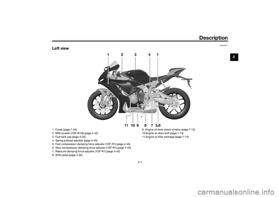
1. Fuses (page 7-34)
2. ERS coupler (YZF-R1M) (page 4-42)
3. Fuel tank cap (page 4-35)
4. Spring preload adjuster (page 4-45)
5. Fast compression damping force adjuster (YZF-R1) (page 4-45)
6. Slow compression damping force adjuster (YZF-R1) (page 4-45)
7. Rebound damping force adjuster (YZF-R1) (page 4-45)
8. Shift pedal (page 4-32)9. Engine oil level check window (page 7-13)
10.Engine oil drain bolt (page 7-13)
11.Engine oil filter cartridge (page 7-13)
UB3LE1E0.book Page 1 Tuesday, August 10, 2021 2:28 PM
Page 16 of 136
Description
2-2
2
EAU10421
Right view
1 2,3,4
5
7
8
6
9
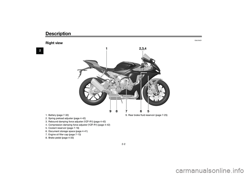
1. Battery (page 7-32)
2. Spring preload adjuster (page 4-42)
3. Rebound damping force adjuster (YZF-R1) (page 4-42)
4. Compression damping force adjuster (YZF-R1) (page 4-42)
5. Coolant reservoir (page 7-16)
6. Document storage space (page 4-41)
7. Engine oil filler cap (page 7-13)
8. Brake pedal (page 4-33) 9. Rear brake fluid reservoir (page 7-25)UB3LE1E0.book Page 2 Tuesday, August 10, 2021 2:28 PM
Page 18 of 136
Special features
3-1
3
EAU6629D
YRC (Yamaha Ride Control)Yamaha Ride Control is a system that
incorporates numerous sensors and
controls to support an improved riding
experience. The vehicle senses and
can react to forces along the longitudi-
nal (front-to-back), lateral (left-to-right),
and vertical (up-and-down) axes. Lean
angle and G-force accelerations are
also detected. This information is pro-
cessed multiple times a second and
the related physical systems are auto-
matically adjusted as necessary. The
following functions represent individual
YRC items which can be turned on/off
or adjusted to suit various riders and
riding conditions. For setting details,
see pages 4-12 and 4-16.
WARNING
EWA18221
The Yamaha Ri de Control (YRC) sys-
tem is not a su bstitute for the use of
proper ri din g techniques or the ex-
pertise of the operator. This system
cannot prevent loss of control
caused b y ri der errors such as trav-
elin g faster than warranted b y roa d
an d traffic con ditions, inclu din g loss of traction
due to excessive spee d
when enterin g turns, when acceler-
atin g har d at a sharp lean an gle, or
while brakin g, an d it cannot prevent
front wheel slip or front wheel lift. As
with any motorcycle, always ri de
within in your limits, be aware of sur-
roun din g con ditions, an d ri de ap-
propriately for those con ditions.
Become thorou ghly familiar with the
way the motorcycle han dles with
various YRC settin gs before at-
temptin g more a dvance d maneu-
vers.
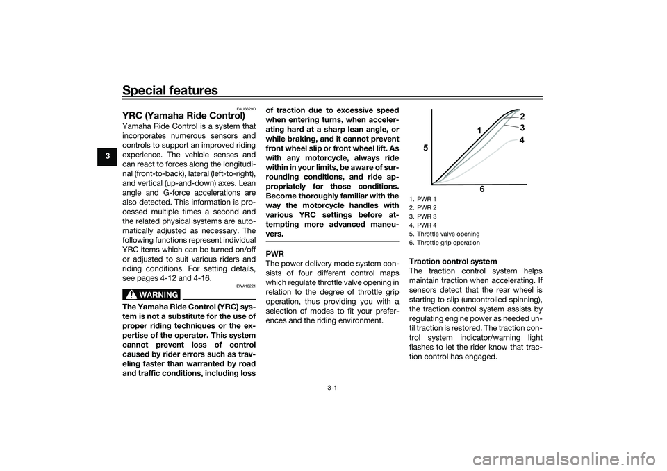
PWR
The power delivery mode system con-
sists of four different control maps
which regulate throttle valve opening in
relation to the degree of throttle grip
operation, thus providing you with a
selection of modes to fit your prefer-
ences and the riding environment. Traction control system
The traction control system helps
maintain traction when accelerating. If
sensors detect that the rear wheel is
starting to slip (uncontrolled spinning),
the traction control system assists by
regulating engine power as needed un-
til traction is restored. The traction con-
trol system indicator/warning light
flashes to let the rider know that trac-
tion control has engaged.
1. PWR 1
2. PWR 2
3. PWR 3
4. PWR 4
5. Throttle valve opening
6. Throttle grip operation
5
64
3 2
1
UB3LE1E0.book Page 1 Tuesday, August 10, 2021 2:28 PM
Page 19 of 136
Special features
3-2
3
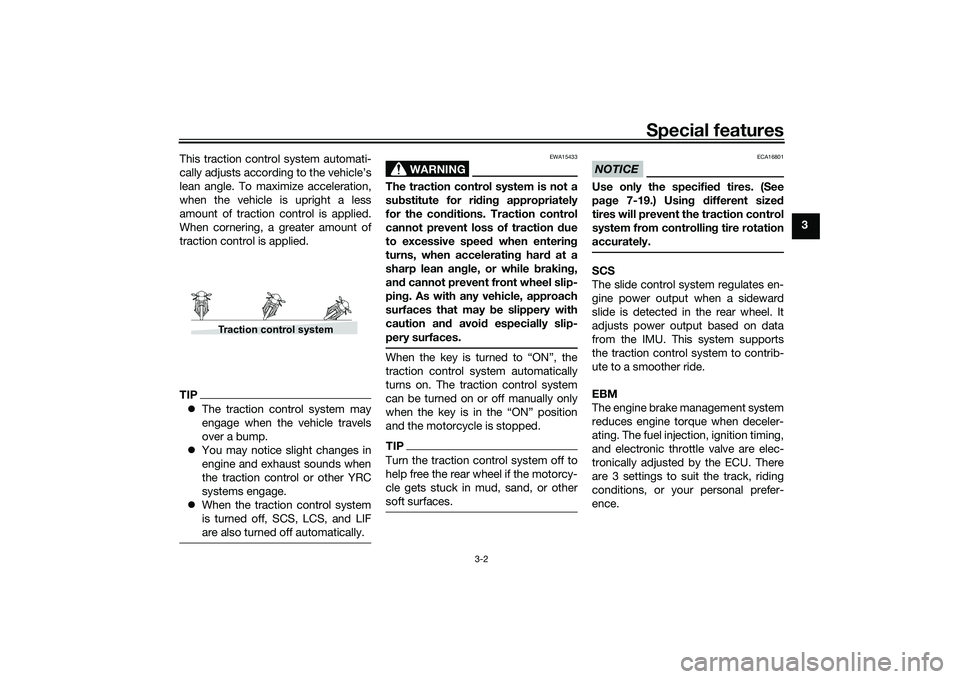
This traction control system automati-
cally adjusts according to the vehicle’s
lean angle. To maximize acceleration,
when the vehicle is upright a less
amount of traction control is applied.
When cornering, a greater amount of
traction control is applied.
TIP
The traction control system may
engage when the vehicle travels
over a bump.
You may notice slight changes in
engine and exhaust sounds when
the traction control or other YRC
systems engage.
When the traction control system
is turned off, SCS, LCS, and LIF
are also turned off automatically.
WARNING
EWA15433
The traction control system is not a
substitute for ri din g appropriately
for the con ditions. Traction control
cannot prevent loss of traction d ue
to excessive spee d when enterin g
turns, when acceleratin g har d at a
sharp lean an gle, or while brakin g,
an d cannot prevent front wheel slip-
pin g. As with any vehicle, approach
surfaces that may be slippery with
caution an d avoi d especially slip-
pery surfaces.When the key is turned to “ON”, the
traction control system automatically
turns on. The traction control system
can be turned on or off manually only
when the key is in the “ON” position
and the motorcycle is stopped.TIPTurn the traction control system off to
help free the rear wheel if the motorcy-
cle gets stuck in mud, sand, or other
soft surfaces.
NOTICE
ECA16801
Use only the specifie d tires. (See
pa ge 7-19.) Usin g different size d
tires will prevent the traction control
system from controllin g tire rotation
accurately.SCS
The slide control system regulates en-
gine power output when a sideward
slide is detected in the rear wheel. It
adjusts power output based on data
from the IMU. This system supports
the traction control system to contrib-
ute to a smoother ride.
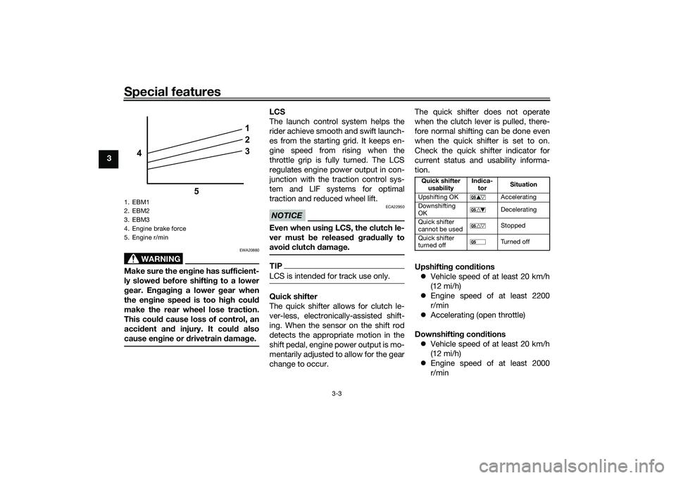
EBM
The engine brake management system
reduces engine torque when deceler-
ating. The fuel injection, ignition timing,
and electronic throttle valve are elec-
tronically adjusted by the ECU. There
are 3 settings to suit the track, riding
conditions, or your personal prefer-
ence.
Traction control system
UB3LE1E0.book Page 2 Tuesday, August 10, 2021 2:28 PM
Page 20 of 136
Special features
3-3
3
WARNING
EWA20880
Make sure the engine has sufficient-
ly slowe d b efore shiftin g to a lower
g ear. En gag in g a lower gear when
the en gine speed is too high coul d
make the rear wheel lose traction.
This coul d cause loss of control, an
acci dent an d injury. It coul d also
cause en gine or d rivetrain damag e.
LCS
The launch control system helps the
rider achieve smooth and swift launch-
es from the starting grid. It keeps en-
gine speed from rising when the
throttle grip is fully turned. The LCS
regulates engine power output in con-
junction with the traction control sys-
tem and LIF systems for optimal
traction and reduced wheel lift.NOTICE
ECA22950
Even when usin g LCS, the clutch le-
ver must b e released g ra dually to
avoi d clutch damag e.TIPLCS is intended for track use only.Quick shifter
The quick shifter allows for clutch le-
ver-less, electronically-assisted shift-
ing. When the sensor on the shift rod
detects the appropriate motion in the
shift pedal, engine power output is mo-
mentarily adjusted to allow for the gear
change to occur. The quick shifter does not operate
when the clutch lever is pulled, there-
fore normal shifting can be done even
when the quick shifter is set to on.
Check the quick shifter indicator for
current status and usability informa-
tion.
Upshiftin
g con ditions
Vehicle speed of at least 20 km/h
(12 mi/h)
Engine speed of at least 2200
r/min
Accelerating (open throttle)
Downshiftin g con ditions
Vehicle speed of at least 20 km/h
(12 mi/h)
Engine speed of at least 2000
r/min
1. EBM1
2. EBM2
3. EBM3
4. Engine brake force
5. Engine r/min
1
2
3
4
5
Quick shifter usa bility In
dica-
tor Situation
Upshifting OK Accelerating
Downshifting
OK Decelerating
Quick shifter
cannot be used Stopped
Quick shifter
turned off Tu r n e d o f f
UB3LE1E0.book Page 3 Tuesday, August 10, 2021 2:28 PM
Page 21 of 136
Special features
3-4
3
Engine speed sufficiently away
from red zone
Decelerating and throttle fully-
closed
TIPQS and QS can be individ-
ually set.
Shifting into or out of neutral must
be done using the clutch lever.LIF
The lift control system reduces the rate
at which the front wheel will continue to
rise during extreme acceleration, such
as during starts or out-of-corner exits.
When front-wheel lift is detected, en-
gine power is regulated to slow front-
wheel lift while still providing good ac-
celeration.
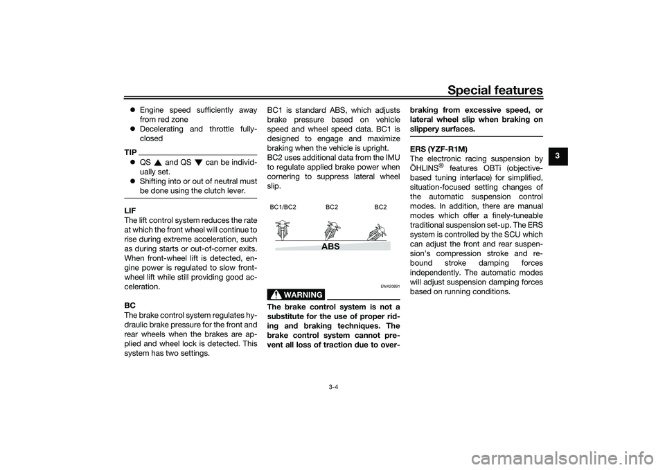
BC
The brake control system regulates hy-
draulic brake pressure for the front and
rear wheels when the brakes are ap-
plied and wheel lock is detected. This
system has two settings. BC1 is standard ABS, which adjusts
brake pressure based on vehicle
speed and wheel speed data. BC1 is
designed to engage and maximize
braking when the vehicle is upright.
BC2 uses additional data from the IMU
to regulate applied brake power when
cornering to suppress lateral wheel
slip.
WARNING
EWA20891
The
brake control system is not a
su bstitute for the use of proper ri d-
in g an d brakin g techniques. The
b rake control system cannot pre-
vent all loss of traction due to over- b
rakin g from excessive spee d, or
lateral wheel slip when brakin g on
slippery surfaces.
ERS (YZF-R1M)
The electronic racing suspension by
ÖHLINS
® features OBTi (objective-
based tuning interface) for simplified,
situation-focused setting changes of
the automatic suspension control
modes. In addition, there are manual
modes which offer a finely-tuneable
traditional suspension set-up. The ERS
system is controlled by the SCU which
can adjust the front and rear suspen-
sion’s compression stroke and re-
bound stroke damping forces
independently. The automatic modes
will adjust suspension damping forces
based on running conditions.
ABS
BC1/BC2 BC2 BC2
UB3LE1E0.book Page 4 Tuesday, August 10, 2021 2:28 PM