maintenance YAMAHA YZF-R1 2022 Owners Manual
[x] Cancel search | Manufacturer: YAMAHA, Model Year: 2022, Model line: YZF-R1, Model: YAMAHA YZF-R1 2022Pages: 136, PDF Size: 6.01 MB
Page 1 of 136
DIC183
YZF1000 (YZF-R1)
YZF1000D (YZF-R1M)
1
2
3
4
5
6
7
8
9
10
11
B3L-28199-E1
Read this manual carefully
before operating this vehicle.
MOTORCYCLE
OWNER’S MANUAL
Specifications
Consumer information
Motorcycle care and storage
Periodic maintenance and adjustment
For your safety – pre-operation checks
Instrument and control functions Special featuresDescription
Safety information
Operation and important riding points Index
[English (E)]
Page 8 of 136
Table of contentsSafety information ............................ 1-1
Description ....................................... 2-1
Left view ......................................... 2-1
Right view ....................................... 2-2
Controls and instruments ............... 2-3
Special features .............................. 3-1
YRC (Yamaha Ride Control) ........... 3-1
Glossary ......................................... 3-5
YRC functions visual guide ............ 3-6
Instrument an d control functions ... 4-1
Immobilizer system......................... 4-1
Main switch/steering lock............... 4-2
Handlebar switches ........................ 4-3
Indicator lights and warning
lights............................................ 4-6
Display ............................................ 4-9
MENU screen ............................... 4-15
Clutch lever .................................. 4-32
Shift pedal .................................... 4-32
Brake lever.................................... 4-33
Brake pedal .................................. 4-33
Brake control system (BC)............ 4-34
Fuel tank cap ................................ 4-35
Fuel ............................................... 4-36
Fuel tank overflow hose ............... 4-37
Catalytic converter ....................... 4-38
Seats ............................................ 4-38
CCU (for equipped models).......... 4-40 Seat cover (for equipped
models) ...................................... 4-41
Document storage ........................ 4-41
Rear view mirrors .......................... 4-42
Adjusting the front fork ................. 4-42
Adjusting the shock absorber assembly.................................... 4-45
EXUP system ................................ 4-49
Auxiliary DC connector ................. 4-49
Sidestand ...................................... 4-49
Ignition circuit cut-off system ....... 4-50
For your safety – pre-operation
checks ............................................... 5-1
Operation an d important ri din g
points ................................................. 6-1
Engine break-in ............................... 6-1
Starting the engine .......................... 6-2
Shifting ............................................ 6-3
Tips for reducing fuel consumption ................................ 6-4
Parking ............................................ 6-4
Perio dic maintenance an d
a d justment ........................................ 7-1
Tool kit ............................................ 7-2
Periodic maintenance charts .......... 7-3
Periodic maintenance chart for the emission control system .............. 7-3 General maintenance and
lubrication chart .......................... 7-5
Cowlings and panels ...................... 7-9
Checking the spark plugs ............. 7-12
Canister ........................................ 7-13
Engine oil and oil filter cartridge ... 7-13
Why Yamalube.............................. 7-16
Coolant ......................................... 7-16
Air filter element ............................ 7-18
Checking the engine idling speed ........................................ 7-18
Valve clearance............................. 7-18
Tires .............................................. 7-19
Cast magnesium wheels .............. 7-21
Adjusting the clutch lever free play ............................................ 7-22
Checking the brake lever free
play ............................................ 7-23
Brake light switches ..................... 7-24
Checking the front and rear brake pads ................................ 7-24
Checking the brake fluid level ...... 7-25
Changing the brake fluid .............. 7-26
Drive chain slack........................... 7-26
Cleaning and lubricating the drive chain ................................. 7-28
Checking and lubricating the cables ........................................ 7-28
Checking and lubricating the
throttle grip ................................ 7-29UB3LE1E0.book Page 1 Tuesday, August 10, 2021 2:28 PM
Page 10 of 136
1-1
1
Safety information
EAU1028C
Be a Responsible Owner
As the vehicle’s owner, you are re-
sponsible for the safe and proper oper-
ation of your motorcycle.
Motorcycles are single-track vehicles.
Their safe use and operation are de-
pendent upon the use of proper riding
techniques as well as the expertise of
the operator. Every operator should
know the following requirements be-
fore riding this motorcycle.
He or she should: Obtain thorough instructions from
a competent source on all aspects
of motorcycle operation.
Observe the warnings and mainte-
nance requirements in this Own-
er’s Manual.
Obtain qualified training in safe
and proper riding techniques.
Obtain professional technical ser-
vice as indicated in this Owner’s
Manual and/or when made neces-
sary by mechanical conditions.
Never operate a motorcycle with-
out proper training or instruction.
Take a training course. Beginners
should receive training from a cer-
tified instructor. Contact an autho-
rized motorcycle dealer to find out
about the training courses nearest
you.
Safe Ri din g
Perform the pre-operation checks
each time you use the vehicle to make
sure it is in safe operating condition.
Failure to inspect or maintain the vehi-
cle properly increases the possibility of
an accident or equipment damage.
See page 5-1 for a list of pre-operation
checks. This motorcycle is designed to
carry the operator and a passen-
ger.
The failure of motorists to detect
and recognize motorcycles in traf-
fic is the predominating cause of
automobile/motorcycle accidents.
Many accidents have been
caused by an automobile driver
who did not see the motorcycle.
Making yourself conspicuous ap- pears to be very effective in reduc-
ing the chance of this type of
accident.
Therefore:
• Wear a brightly colored jacket.
• Use extra caution when you are approaching and passing
through intersections, since in-
tersections are the most likely
places for motorcycle accidents
to occur.
• Ride where other motorists can see you. Avoid riding in another
motorist’s blind spot.
• Never maintain a motorcycle without proper knowledge.
Contact an authorized motorcy-
cle dealer to inform you on ba-
sic motorcycle maintenance.
Certain maintenance can only
be carried out by certified staff.UB3LE1E0.book Page 1 Tuesday, August 10, 2021 2:28 PM
Page 30 of 136
Instrument and control functions
4-7
4
TIPThe engine is sensitively monitored by
the on-board diagnostic system to de-
tect deterioration or malfunction of the
emission control system. Therefore the
MIL may come on or flash due to vehi-
cle modifications, lack of maintenance,
or excessive/improper use of the mo-
torcycle. To prevent this, observe
these precautions.
Do not attempt to modify the soft-
ware of the engine control unit.
Do not add any electrical acces-
sories that interfere with engine
control.
Do not use aftermarket accesso-
ries or parts such as suspension,
spark plugs, injectors, exhaust
system, etc.
Do not change the drivetrain
specifications (chain, sprockets,
wheels, tires, etc.).
Do not remove or alter the O2 sen-
sor, air induction system, or ex-
haust parts (catalysts or EXUP,
etc.).
Maintain the drive chain properly.
Maintain correct tire pressure.
Maintain proper brake pedal
height to prevent rear brake from
dragging.
Do not operate the vehicle in an
extreme manner. For example, re-
peated or excessive opening and
closing of the throttle, racing,
burnouts, wheelies, extended
half-clutch use, etc.
EAU88342
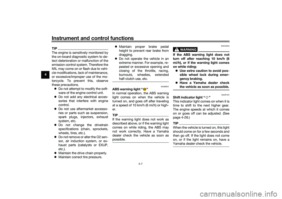
ABS warnin g li ght “ ”
In normal operation, the ABS warning
light comes on when the vehicle is
turned on, and goes off after traveling
at a speed of 10 km/h (6 mi/h) or high-
er.TIPIf the warning light does not work as
described above, or if the warning light
comes on while riding, the ABS may
not work correctly. Have a Yamaha
dealer check the vehicle as soon as
possible.
WARNING
EWA16043
If the ABS warnin g li ght does not
turn off after reachin g 10 km/h (6
mi/h), or if the warnin g li ght comes
on while ri din g:
Use extra caution to avoi d pos-
si ble wheel lock d uring emer-
g ency brakin g.
Have a Yamaha d ealer check
the vehicle as soon as possi ble.
EAU67434
Shift in dicator li ght “ ”
This indicator light comes on when it is
time to shift to the next higher gear.
The engine speeds at which it comes
on or goes off can be adjusted. (See
page 4-26.)TIPWhen the vehicle is turned on, this light
should come on for a few seconds and
then go off. If the light does not come
on, or if the light remains on, have a
Yamaha dealer check the vehicle.
UB3LE1E0.book Page 7 Tuesday, August 10, 2021 2:28 PM
Page 38 of 136
Instrument and control functions
4-15
4 Error mo
de warnin g “Err”
When an internal error occurs (e.g.,
communication with a system control-
ler has been cut off), the error mode
warning will appear as follows.
“Err” and “ ” indicates an ECU error.
“Err” and “ ” indicates an SCU error.
“Err” only indicates an ABS ECU error.
TIPDepending on the nature of the error,
the display may not function properly
and YRC settings may be impossible
to change. Additionally, ABS may not
function properly. Use extra care when
braking and have a Yamaha dealer
check the vehicle immediately.
EAU7929B
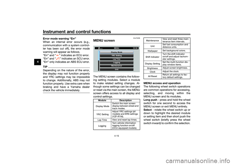
MENU screenThe MENU screen contains the follow-
ing setting modules. Select a module
to make related setting changes. Al-
though some settings can be changed
or reset via the main screen, the MENU
screen offers access to all display and
control settings. MENU access an
d operation
The following wheel switch operations
are common operations for accessing,
selecting, and moving within the
MENU screen and its modules.
Lon g push - press and hold the wheel
switch for one second to access the
MENU screen or exit MENU entirely.
Select - rotate the wheel switch up or
down to highlight the desired module
or setting item and then short push the
wheel switch (briefly press the wheel
switch inward) to confirm the selection.
Mo dule Description
Switch the main screen
display between street and
track modes.
Adjust YRC settings (all
models) and ERS settings
(YZF-R1M).
View and reset lap times.
Turn vehicle information
logging function on/off
(CCU-equipped models).
YRC Setting
Lap TimeLogging
Maintenance
Unit
Display ModeMENU
km/h
GPS
10
:
00
Display ModeYRC SettingLogging
View and reset three main-
tenance item intervals.
Set fuel consumption and
distance units.
Set background colors.
Turn the shift indicator
on/off and adjust tachom-
eter settings.
Set the multi-function dis-
play window items.
Adjust screen brightness.
Adjust the clock.
Return all settings to fac-
tory default settings.
Maintenance
Unit
WallpaperShift IndicatorDisplay SettingBrightnessClockAll Reset
UB3LE1E0.book Page 15 Tuesday, August 10, 2021 2:28 PM
Page 39 of 136
Instrument and control functions
4-16
4
Trian
gle mark - certain setting
screens have an upward pointing trian-
gle mark item. Select the triangle mark
to save setting changes made and exit
that screen.
TIP Should vehicle motion be detect-
ed, the screen will automatically
exit MENU and change to the
main screen.
To ensure that the desired setting
changes are saved, be sure to exit
via the triangle mark. Simply per-
forming a long push and exiting
the MENU screen entirely may not
save setting changes.“Display Mo de”
There are two main screen display
modes, STREET MODE and TRACK
MODE.
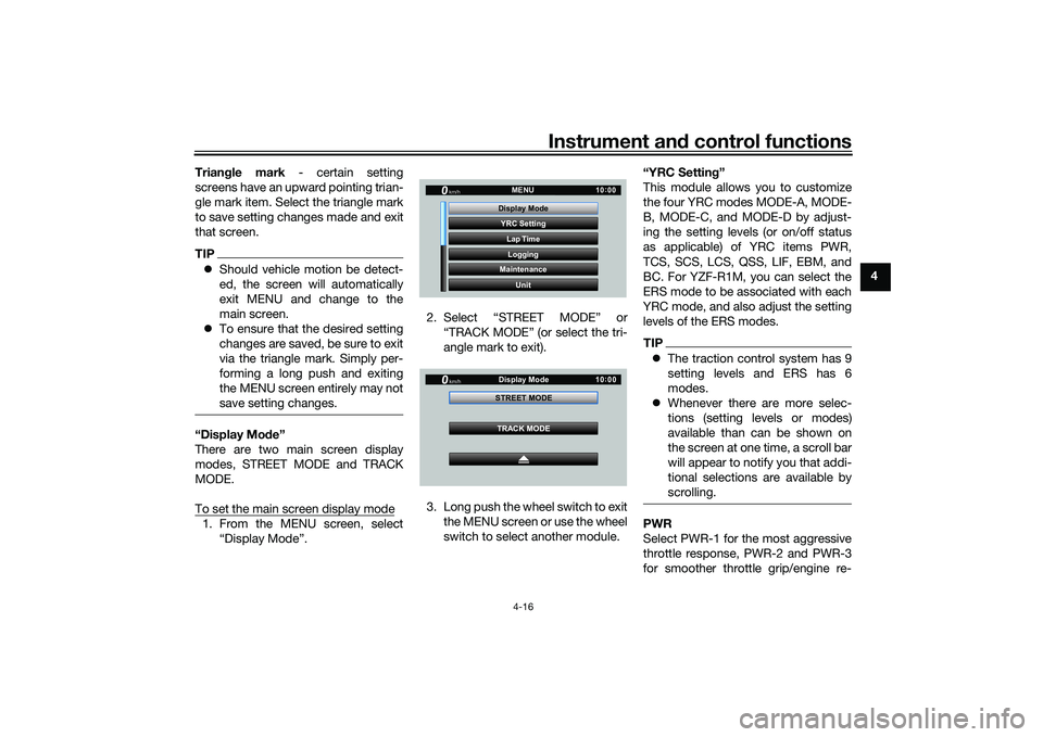
To set the main screen display mode1. From the MENU screen, select “Display Mode”. 2. Select “STREET MODE” or
“TRACK MODE” (or select the tri-
angle mark to exit).
3. Long push the wheel switch to exit the MENU screen or use the wheel
switch to select another module. “YRC Settin
g”
This module allows you to customize
the four YRC modes MODE-A, MODE-
B, MODE-C, and MODE-D by adjust-
ing the setting levels (or on/off status
as applicable) of YRC items PWR,
TCS, SCS, LCS, QSS, LIF, EBM, and
BC. For YZF-R1M, you can select the
ERS mode to be associated with each
YRC mode, and also adjust the setting
levels of the ERS modes.
TIP The traction control system has 9
setting levels and ERS has 6
modes.
Whenever there are more selec-
tions (setting levels or modes)
available than can be shown on
the screen at one time, a scroll bar
will appear to notify you that addi-
tional selections are available by
scrolling.PWR
Select PWR-1 for the most aggressive
throttle response, PWR-2 and PWR-3
for smoother throttle grip/engine re-
YRC Setting
Lap TimeLogging
Maintenance
Unit
Display ModeMENU
km/h
GPS
10
:
00
km/h
10 :
00
TRACK MODE
STREET MODE
Display Mode
UB3LE1E0.book Page 16 Tuesday, August 10, 2021 2:28 PM
Page 42 of 136
Instrument and control functions
4-19
4
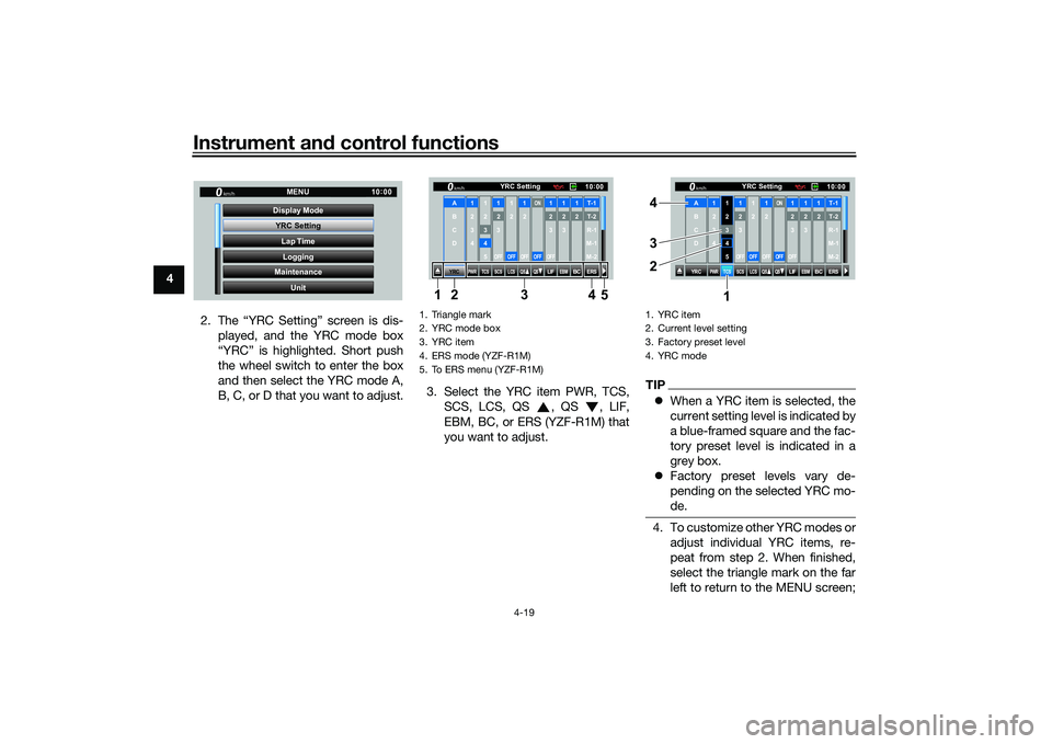
2. The “YRC Setting” screen is dis-played, and the YRC mode box
“YRC” is highlighted. Short push
the wheel switch to enter the box
and then select the YRC mode A,
B, C, or D that you want to adjust. 3. Select the YRC item PWR, TCS,
SCS, LCS, QS , QS , LIF,
EBM, BC, or ERS (YZF-R1M) that
you want to adjust.
TIPWhen a YRC item is selected, the
current setting level is indicated by
a blue-framed square and the fac-
tory preset level is indicated in a
grey box.
Factory preset levels vary de-
pending on the selected YRC mo-
de.4. To customize other YRC modes or
adjust individual YRC items, re-
peat from step 2. When finished,
select the triangle mark on the far
left to return to the MENU screen;
YRC Setting
Lap TimeLogging
Maintenance
Unit
Display ModeMENU
km/h
GPS
10
:
00
1. Triangle mark
2. YRC mode box
3. YRC item
4. ERS mode (YZF-R1M)
5. To ERS menu (YZF-R1MF
YRC
PWR
TCS
SCS
LCSQS
QS
LIFEBM
BC
ERS10 :
00
YRC Setting
km/hA
B
C
D
1
2
3
4
1 2345
12
3OFF
1 2OFF
12OFF
ON
OFF
12
3OFF
12
3
12T-1T-2
R-1
M-1
M-2
134 5
2
1. YRC item
2. Current level setting
3. Factory preset level
4. YRC mode
YRC
PWR
TCS
SCS
LCSQS
QS
LIFEBM
BC
ERS10:
00
YRC Setting
km/hA
B
C
D
1
2
3
4
1 2345
12
3OFF
1 2OFF
12OFF
ON
OFF
12
3OFF
12
3
12T-1T-2
R-1
M-1
M-2
1
3 4
2
UB3LE1E0.book Page 19 Tuesday, August 10, 2021 2:28 PM
Page 45 of 136
Instrument and control functions
4-22
4
3. Select the suspension item that
you want to adjust, and then ro-
tate the wheel switch to adjust the
setting level.
TIPAll ERS modes regardless of type are
independent. Offset level setting
changes made in one mode are not
transferred to another mode.4. To adjust other ERS modes of thesame type, repeat from step 1. To
switch types or when finished, se-
lect the Ž mark to return to the
“Lap Time”
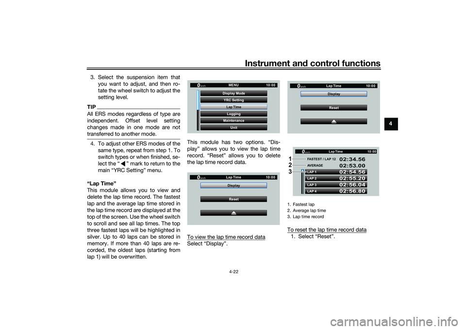
This module allows you to view and
delete the lap time record. The fastest
lap and the average lap time stored in
the lap time record are displayed at the
top of the screen. Use the wheel switch
to scroll and see all lap times. The top
three fastest laps will be highlighted in
silver. Up to 40 laps can be stored in
memory. If more than 40 laps are re-
corded, the oldest laps (starting from
lap 1) will be overwritten. This module has two options. “Dis-
play” allows you to view the lap time
record. “Reset” allows you to delete
the lap time record data.
To view the lap time record data
Select “Display”.
To reset the lap time record data
1. Select “Reset”.
YRC Setting
Lap TimeLogging
Maintenance
Unit
Display ModeMENU
km/h
GPS
10
:
00
km/h
10 :
00
Reset
Display
Lap Time
1. Fastest lap
2. Average lap time
3. Lap time record
km/h
10
:
00
Reset
Display
Lap Time
LAP 1
LAP 2
LAP 3
LAP 4 FASTEST / LAP 12
02:54.56
02:55.20
02:56.04
02:56.80 02:34.56
02:53.00
AVERAGE Lap Timekm/h
GP GPS
10
:
00
1
2
3
UB3LE1E0.book Page 22 Tuesday, August 10, 2021 2:28 PM
Page 46 of 136
Instrument and control functions
4-23
4
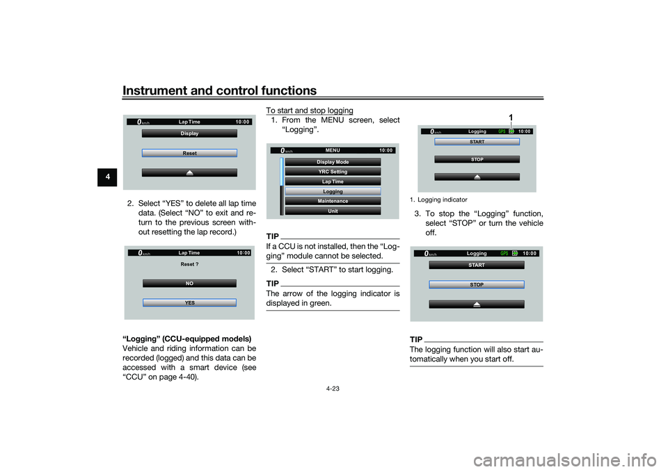
2. Select “YES” to delete all lap timedata. (Select “NO” to exit and re-
turn to the previous screen with-
out resetting the lap record.)
“Lo ggin g” (CCU-equippe d mo dels)
Vehicle and riding information can be
recorded (logged) and this data can be
accessed with a smart device (see
“CCU” on page 4-40). To start and stop logging
1. From the MENU screen, select
“Logging”.TIP
gingŽ module cannot be selected.2. TIPThe arrow of the logging indicator is
displayed in green.
3.
off.TIPThe logging function will also start au-
tomatically when you start off.
km/h
10:
00
Reset
Display
Lap TimeNO
Reset ?
Lap Time
YES
km/h
GP GPS
10:
00
YRC Setting
Lap TimeLogging
Maintenance
Unit
Display ModeMENU
km/h
GPS
10
:
00
1. Logging indicator
STOP
START
Logging
km/h
10
:
00
GPS
1
STOP
START
Logging
km/h
10
:
00
GPS
UB3LE1E0.book Page 23 Tuesday, August 10, 2021 2:28 PM
Page 47 of 136
Instrument and control functions
4-24
4
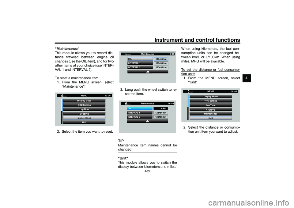
“Maintenance”
This module allows you to record dis-
tance traveled between engine oil
changes (use the OIL item), and for two
other items of your choice (use INTER-
VAL 1 and INTERVAL 2).
To reset a maintenance item
1. From the MENU screen, select
“Maintenance”.
2. Select the item you want to reset. 3. Long push the wheel switch to re-
set the item.
TIPMaintenance item names cannot be
changed.“Unit”
This module allows you to switch the
display between kilometers and miles. When using kilometers, the fuel con-
sumption units can be changed be-
tween km/L or L/100km. When using
miles, MPG will be available.
To set the distance or fuel consump-
tion units1. From the MENU screen, select
“Unit”.
2. Select the distance or consump- tion unit item you want to adjust.
YRC Setting
Lap TimeLogging
Maintenance
Unit
Display ModeMENU
km/h
GPS
10
:
00
INTERVAL 2 OIL
INTERVAL 1 123456 km
123456 km
123456 km
Maintenancekm/h
GPS
10
:
00
INTERVAL 2 OIL
INTERVAL 1 123456 km
123456 km
Maintenancekm/h
GPS
10
:
00
0 km
YRC Setting
Lap TimeLogging
Maintenance
Unit
Display ModeMENU
km/h
GPS
10
:
00
UB3LE1E0.book Page 24 Tuesday, August 10, 2021 2:28 PM