check engine YAMAHA YZF-R1 2022 User Guide
[x] Cancel search | Manufacturer: YAMAHA, Model Year: 2022, Model line: YZF-R1, Model: YAMAHA YZF-R1 2022Pages: 136, PDF Size: 6.01 MB
Page 72 of 136

Instrument and control functions
4-49
4
EAU67050
EXUP systemThis model is equipped with Yamaha’s
EXUP (EXhaust Ultimate Power valve)
system. This system boosts engine
power by means of a valve that con-
trols exhaust flow within the exhaust
chamber.NOTICE
ECA15611
The EXUP system has been set and
extensively tested at the Yamaha
factory. Changing these settings
without sufficient technical knowl-
edge may result in poor perfor-
mance of or damage to the engine.
EAU70641
Auxiliary DC connectorThis vehicle is equipped with an auxil-
iary DC connector. Consult your
Yamaha dealer before installing any accessories.
EAU15306
SidestandThe sidestand is located on the left
side of the frame. Raise the sidestand
or lower it with your foot while holding
the vehicle upright.TIPThe built-in sidestand switch is part of
the ignition circuit cut-off system,
which cuts the ignition in certain situa-
tions. (See the following section for an
explanation of the ignition circuit cut-
off system.)
WARNING
EWA10242
The vehicle must not be ridden with
the sidestand down, or if the side-
stand cannot be properly moved up (or does not stay up), otherwise the
sidestand could contact the ground
and distract the operator, resulting
in a possible loss of control.
Yamaha’s ignition circuit cut-off system has been designed to assist
the operator in fulfilling the respon-
sibility of raising the sidestand be-
fore starting off. Therefore, check
UB3LE1E0.book Page 49 Tuesday, August 10, 2021 2:28 PM
Page 73 of 136

Instrument and control functions
4-50
4
this system regularly and have a
Yamaha dealer repair it if it does not function properly.
EAU57952
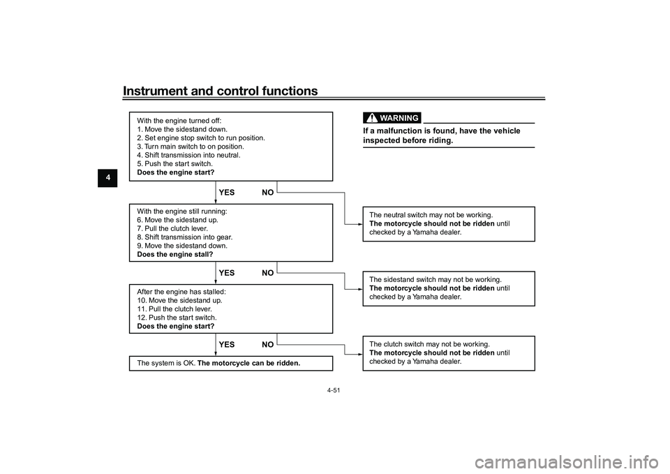
Ignition circuit cut-off systemThis system prevents in-gear engine
starts unless the clutch lever is pulled
and the sidestand is up. Also, it will
stop the running engine should the
sidestand be lowered while the trans-
mission is in gear.
Periodically check this system via the
following procedure.TIP This check is most reliable if per-
formed with a warmed-up engine.
See pages 4-2 and 4-3 for switch
operation information.
UB3LE1E0.book Page 50 Tuesday, August 10, 2021 2:28 PM
Page 74 of 136

Instrument and control functions
4-51
4
With the engine turned off:
1. Move the sidestand down.
2. Set engine stop switch to run position.
3. Turn main switch to on position.
4. Shift transmission into neutral.
5. Push the start switch.
Does the engine start?
With the engine still running:
6. Move the sidestand up.
7. Pull the clutch lever.
8. Shift transmission into gear.
9. Move the sidestand down.
Does the engine stall?
After the engine has stalled:
10. Move the sidestand up.
11. Pull the clutch lever.
12. Push the start switch.
Does the engine start?
The system is OK. The motorcycle can be ridden.
YES NO YES NO YES NO
The neutral switch may not be working.
The motorcycle should not be ridden until
checked by a Yamaha dealer.
The clutch switch may not be working.
The motorcycle should not be ridden until
checked by a Yamaha dealer.The sidestand switch may not be working.
The motorcycle should not be ridden until
checked by a Yamaha dealer.If a malfunction is found, have the vehicle
inspected before riding.
WARNING
UB3LE1E0.book Page 51 Tuesday, August 10, 2021 2:28 PM
Page 75 of 136

For your safety – pre-operation checks
5-1
5
EAU1559B
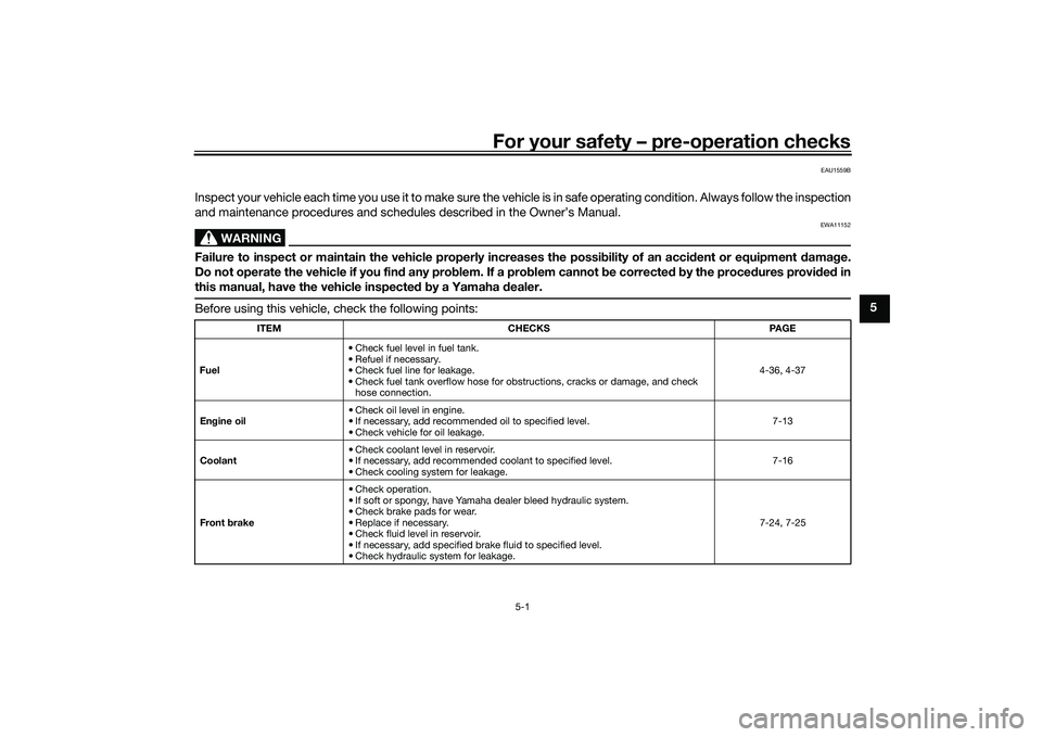
Inspect your vehicle each time you use it to make sure the vehicle is in safe operating condition. Always follow the inspection
and maintenance procedures and schedules described in the Owner’s Manual.
WARNING
EWA11152
Failure to inspect or maintain the vehicle properly increases the possibility of an accident or equipment damage.
Do not operate the vehicle if you find any problem. If a problem cannot be corrected by the procedures provided in
this manual, have the vehicle inspected by a Yamaha dealer.Before using this vehicle, check the following points:
ITEM CHECKS PAGE
Fuel • Check fuel level in fuel tank.
• Refuel if necessary.
• Check fuel line for leakage.
• Check fuel tank overflow hose for obstructions, cracks or damage, and check
hose connection. 4-36, 4-37
Engine oil • Check oil level in engine.
• If necessary, add recommended oil to specified level.
• Check vehicle for oil leakage. 7-13
Coolant • Check coolant level in reservoir.
• If necessary, add recommended coolant to specified level.
• Check cooling system for leakage. 7-16
Front brake • Check operation.
• If soft or spongy, have Yamaha dealer bleed hydraulic system.
• Check brake pads for wear.
• Replace if necessary.
• Check fluid level in reservoir.
• If necessary, add specified brake fluid to specified level.
• Check hydraulic system for leakage. 7-24, 7-25
UB3LE1E0.book Page 1 Tuesday, August 10, 2021 2:28 PM
Page 78 of 136

Operation and important riding points
6-1
6
EAU15952
Read the Owner’s Manual carefully to
become familiar with all controls. If
there is a control or function you do not
understand, ask your Yamaha dealer.
WARNING
EWA10272
Failure to familiarize yourself with
the controls can lead to loss of con-
trol, which could cause an accident
or injury.
EAU16842
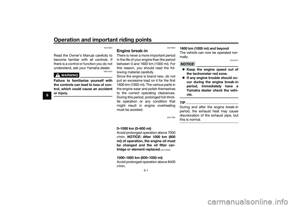
Engine break-inThere is never a more important period
in the life of your engine than the period
between 0 and 1600 km (1000 mi). For
this reason, you should read the fol-
lowing material carefully.
Since the engine is brand new, do not
put an excessive load on it for the first
1600 km (1000 mi). The various parts in
the engine wear and polish themselves
to the correct operating clearances.
During this period, prolonged full-throt-
tle operation or any condition that
might result in engine overheating
must be avoided.
EAU17085
0–1000 km (0–600 mi)
Avoid prolonged operation above 7000
r/min. NOTICE: After 1000 km (600
mi) of operation, the engine oil must
be changed and the oil filter car-
tridge or element replaced.
[ECA10303]
1000–1600 km (600–1000 mi)
Avoid prolonged operation above 8400
r/min. 1600 km (1000 mi) and beyond
The vehicle can now be operated nor-
mally.
NOTICE
ECA10311
Keep the engine speed out of
the tachometer red zone.
If any engine trouble should oc-
cur during the engine break-in
period, immediately have a
Yamaha dealer check the vehi-
cle.TIPDuring and after the engine break-in
period, the exhaust heat may cause
discoloration of the exhaust pipe, but
this is normal.
UB3LE1E0.book Page 1 Tuesday, August 10, 2021 2:28 PM
Page 79 of 136

Operation and important riding points
6-2
6
EAU88420
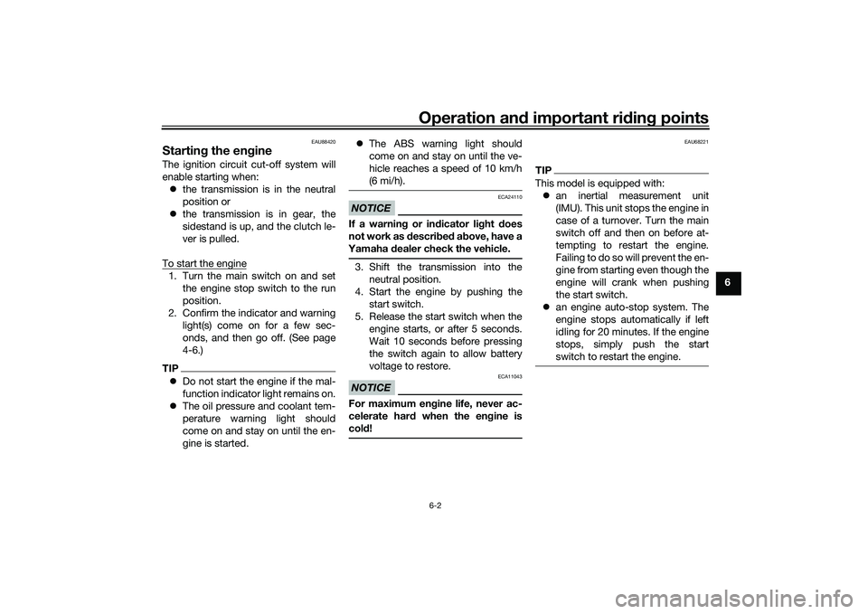
Starting the engineThe ignition circuit cut-off system will
enable starting when: the transmission is in the neutral
position or
the transmission is in gear, the
sidestand is up, and the clutch le-
ver is pulled.
To start the engine1. Turn the main switch on and set the engine stop switch to the run
position.
2. Confirm the indicator and warning light(s) come on for a few sec-
onds, and then go off. (See page
4-6.)TIPDo not start the engine if the mal-
function indicator light remains on.
The oil pressure and coolant tem-
perature warning light should
come on and stay on until the en-
gine is started.
The ABS warning light should
come on and stay on until the ve-
hicle reaches a speed of 10 km/h
(6 mi/h).
NOTICE
ECA24110
If a warning or indicator light does
not work as described above, have a
Yamaha dealer check the vehicle.3. Shift the transmission into the
neutral position.
4. Start the engine by pushing the start switch.
5. Release the start switch when the engine starts, or after 5 seconds.
Wait 10 seconds before pressing
the switch again to allow battery
voltage to restore.NOTICE
ECA11043
For maximum engine life, never ac-
celerate hard when the engine is
cold!
EAU68221
TIPThis model is equipped with: an inertial measurement unit
(IMU). This unit stops the engine in
case of a turnover. Turn the main
switch off and then on before at-
tempting to restart the engine.
Failing to do so will prevent the en-
gine from starting even though the
engine will crank when pushing
the start switch.
an engine auto-stop system. The
engine stops automatically if left
idling for 20 minutes. If the engine
stops, simply push the start
switch to restart the engine.
UB3LE1E0.book Page 2 Tuesday, August 10, 2021 2:28 PM
Page 84 of 136

Periodic maintenance and adjustment
7-3
7
EAU71033
Periodic maintenance chartsTIPItems marked with an asterisk should be performed by your Yamaha dealer because these items require special tools,
data, and technical skills.
From 50000 km (30000 mi), repeat the maintenance intervals starting from 10000 km (6000 mi).
The annual checks must be performed every year, except if a distance-based maintenance is performed in-
stead.
EAU71051
Periodic maintenance chart for the emission control systemNO. ITEM CHECK OR MAINTENANCE JOB ODOMETER READING
ANNUAL
CHECK
1000 km
(600 mi) 10000 km
(6000 mi) 20000 km
(12000 mi) 30000 km
(18000 mi) 40000 km
(24000 mi)
1 *Fuel line • Check fuel hoses for cracks or
damage.
• Replace if necessary. √√√√√
2 *Spark plugs • Check condition.
• Adjust gap and clean.
√√
• Replace. √√
3 *Valve clearance • Check and adjust. Every 40000 km (24000 mi)
4 *Fuel injection • Check engine idle speed.
√√√√√√
• Check and adjust synchroniza- tion. √√√√√
5 *Exhaust system • Check for leakage.
• Tighten if necessary.
• Replace gaskets if necessary. √√√√√
UB3LE1E0.book Page 3 Tuesday, August 10, 2021 2:28 PM
Page 88 of 136

Periodic maintenance and adjustment
7-7
7
20 Sidestand• Check operation.
• Lubricate with lithium-soap-
based grease. √√√√√
21 *Sidestand switch • Check operation and replace if
necessary. √√√√√√
22 *Front fork • Check operation and for oil leak-
age.
• Replace if necessary. √√√√
23 *Shock absorber as-
sembly • Check operation and for oil leak-
age.
• Replace if necessary. √√√√
24 *Rear suspension re-
lay arm and con-
necting arm
pivoting points
• Check operation.
√√√√
25 Engine oil • Change (warm engine before
draining).
• Check oil level and vehicle for oil leakage. √√√√√√
26 Engine oil filter car-
tridge • Replace.
√√√
27 *Cooling system • Check coolant level and vehicle
for coolant leakage. √√√√√
• Change. Every 3 years
28 *EXUP system • Check operation, cable free play
and pulley position. √√√
29 *Front and rear
brake switches
• Check operation.
√√√√√√
NO. ITEM CHECK OR MAINTENANCE JOB
ODOMETER READING
ANNUAL
CHECK
1000 km
(600 mi) 10000 km
(6000 mi) 20000 km
(12000 mi) 30000 km
(18000 mi) 40000 km
(24000 mi)UB3LE1E0.book Page 7 Tuesday, August 10, 2021 2:28 PM
Page 93 of 136

Periodic maintenance and adjustment
7-12
7
EAU67110
Checking the spark plugsThe spark plugs are important engine
components, which should be
checked periodically, preferably by a
Yamaha dealer. Since heat and depos- its will cause any spark plug to slowly
erode, they should be removed and
checked in accordance with the peri-
odic maintenance and lubrication
chart. In addition, the condition of the
spark plugs can reveal the condition of
the engine.
The porcelain insulator around the
center electrode of each spark plug
should be a medium-to-light tan (the
ideal color when the vehicle is ridden
normally), and all spark plugs installed
in the engine should have the same
color. If any spark plug shows a dis-
tinctly different color, the engine could
be operating improperly. Do not at-
tempt to diagnose such problems
yourself. Instead, have a Yamaha deal-
er check the vehicle.
If a spark plug shows signs of elec-
trode erosion and excessive carbon or
other deposits, it should be replaced. Before installing a spark plug, the
spark plug gap should be measured
with a wire thickness gauge and, if
necessary, adjusted to specification.
Clean the surface of the spark plug
gasket and its mating surface, and
then wipe off any grime from the spark
plug threads.
NOTICE
ECA10841
Do not use any tools to remove or in-
stall the spark plug cap, otherwise
the ignition coil coupler may get
damaged. The spark plug cap may
be difficult to remove because the
rubber seal on the end of the cap fits
tightly. To remove the spark plug
cap, simply twist it back and forth
while pulling it out; to install it, twist
it back and forth while pushing it in.
Specified spark plug:
NGK/LMAR9E-J
1. Spark plug gap
Spark plug gap:0.6–0.7 mm (0.024–0.028 in)
1
1
Tightening torque:Spark plug (new):
18 N·m (1.8 kgf·m, 13 lb·ft)
Spark plug (after checking):
13 N·m (1.3 kgf·m, 9.6 lb·ft)
UB3LE1E0.book Page 12 Tuesday, August 10, 2021 2:28 PM
Page 94 of 136

Periodic maintenance and adjustment
7-13
7
EAU36113
CanisterThis model is equipped with a canister
to prevent the discharging of fuel vapor
into the atmosphere. Before operating
this vehicle, make sure to check the
following: Check each hose connection.
Check each hose and canister for
cracks or damage. Replace if
damaged.
Make sure that the canister
breather is not blocked, and if
necessary, clean it.
EAU66536
Engine oil and oil filter car-
tridgeThe engine oil level should be checked
before each ride. In addition, the oil
must be changed and the oil filter car-
tridge replaced at the intervals speci-
fied in the periodic maintenance and
lubrication chart.
To check the engine oil level
1. Place the vehicle on a level surfa- ce and hold it in an upright posi-
tion. A slight tilt to the side can
result in a false reading.
2. Start the engine, warm it up for several minutes, and then turn it
off.
3. Wait a few minutes for the oil level to settle for an accurate reading,
and then check the oil level
through the check window locat-
ed at the bottom-left side of the
crankcase.TIPThe engine oil should be between the
minimum and maximum level marks.
4. If the engine oil is at or below theminimum level mark, add suffi-
cient oil of the recommended type
to raise it to the correct level.TIPCheck the oil filler cap O-ring for dam-
age, and replace it if necessary.To change the engine oil1. Start the engine, warm it up for several minutes, and then turn it
off.
2. Place an oil pan under the engine to collect the used oil.
1. Canister
2. Canister breather
1
2
1. Engine oil level check window
2. Maximum level mark
3. Minimum level mark
2
3
1
UB3LE1E0.book Page 13 Tuesday, August 10, 2021 2:28 PM