brake pads YAMAHA YZF-R125 2015 Owners Manual
[x] Cancel search | Manufacturer: YAMAHA, Model Year: 2015, Model line: YZF-R125, Model: YAMAHA YZF-R125 2015Pages: 98, PDF Size: 6.92 MB
Page 6 of 98

TABLE OF CONTENTSSAFETY INFORMATION.................. 1-1
DESCRIPTION.................................. 2-1
Left view ......................................... 2-1
Right view ....................................... 2-2
Controls and instruments ............... 2-3
INSTRUMENT AND CONTROL
FUNCTIONS...................................... 3-1
Main switch/steering lock............... 3-1
Indicator lights and warning
lights............................................ 3-2
Multi-function meter unit ................ 3-4
Handlebar switches ...................... 3-11
Clutch lever .................................. 3-13
Shift pedal .................................... 3-13
Brake lever.................................... 3-13
Brake pedal .................................. 3-14
ABS (for ABS models) .................. 3-14
Fuel tank cap ................................ 3-15
Fuel ............................................... 3-16
Catalytic converter ....................... 3-17
Rider seat ..................................... 3-18
Sidestand ..................................... 3-18
Ignition circuit cut-off system ....... 3-19FOR YOUR SAFETY –
PRE-OPERATION CHECKS............. 4-1
OPERATION AND IMPORTANT
RIDING POINTS................................ 5-1
Starting the engine .......................... 5-1
Shifting ............................................ 5-2
Tips for reducing fuel
consumption ................................ 5-3
Engine break-in ............................... 5-3
Parking ............................................ 5-4
PERIODIC MAINTENANCE AND
ADJUSTMENT................................... 6-1
Owner’s tool kit ............................... 6-2
Periodic maintenance chart for the
emission control system .............. 6-3
General maintenance and
lubrication chart ........................... 6-4
Removing and installing the
cowlings and panel ...................... 6-8
Checking the spark plug ............... 6-10
Engine oil and oil filter element ..... 6-11
Coolant.......................................... 6-14
Replacing the air filter element
and cleaning the check hose..... 6-16
Checking the engine idling
speed ......................................... 6-16
Adjusting the throttle grip free
play ............................................ 6-17
Valve clearance ............................. 6-17Tires .............................................. 6-18
Cast wheels .................................. 6-20
Adjusting the clutch lever free
play ............................................ 6-21
Checking the front brake lever
free play..................................... 6-22
Adjusting the brake pedal free
play ............................................ 6-22
Brake light switches ..................... 6-22
Checking the front and rear brake
pads .......................................... 6-23
Checking the brake fluid level ...... 6-24
Changing the brake fluid .............. 6-25
Drive chain slack........................... 6-25
Cleaning and lubricating the drive
chain.......................................... 6-27
Checking and lubricating the
cables ........................................ 6-27
Checking and lubricating the
throttle grip and cable ............... 6-28
Checking and lubricating the
brake and clutch levers ............. 6-28
Checking and lubricating the
brake pedal ............................... 6-29
Checking and lubricating the
sidestand................................... 6-29
Lubricating the swingarm
pivots......................................... 6-29
Checking the front fork ................. 6-30
Checking the steering................... 6-30
Checking the wheel bearings ....... 6-31U5D7E5E0.book Page 1 Thursday, August 21, 2014 9:30 AM
Page 36 of 98

FOR YOUR SAFETY – PRE-OPERATION CHECKS
4-1
4
EAU15598
Inspect your vehicle each time you use it to make sure the vehicle is in safe operating condition. Always follow the inspection
and maintenance procedures and schedules described in the Owner’s Manual.
WARNING
EWA11152
Failure to inspect or maintain the vehicle properly increases the possibility of an accident or equipment damage.
Do not operate the vehicle if you find any problem. If a problem cannot be corrected by the procedures provided in
this manual, have the vehicle inspected by a Yamaha dealer.Before using this vehicle, check the following points:
ITEM CHECKS PAGE
Fuel• Check fuel level in fuel tank.
• Refuel if necessary.
• Check fuel line for leakage.3-16
Engine oil• Check oil level in engine.
• If necessary, add recommended oil to specified level.
• Check vehicle for oil leakage.6-11
Coolant• Check coolant level in reservoir.
• If necessary, add recommended coolant to specified level.
• Check cooling system for leakage.6-14
Front brake• Check operation.
• If soft or spongy, have Yamaha dealer bleed hydraulic system.
• Check brake pads for wear.
• Replace if necessary.
• Check fluid level in reservoir.
• If necessary, add specified brake fluid to specified level.
• Check hydraulic system for leakage.6-23, 6-24
U5D7E5E0.book Page 1 Thursday, August 21, 2014 9:30 AM
Page 37 of 98

FOR YOUR SAFETY – PRE-OPERATION CHECKS
4-2
4
Rear brake• Check operation.
• If soft or spongy, have Yamaha dealer bleed hydraulic system.
• Check brake pads for wear.
• Replace if necessary.
• Check fluid level in reservoir.
• If necessary, add specified brake fluid to specified level.
• Check hydraulic system for leakage.6-23, 6-24
Clutch• Check operation.
• Lubricate cable if necessary.
• Check lever free play.
• Adjust if necessary.6-21
Throttle grip• Make sure that operation is smooth.
• Check throttle grip free play.
• If necessary, have Yamaha dealer adjust throttle grip free play and lubricate ca-
ble and grip housing.6-17, 6-28
Control cables• Make sure that operation is smooth.
• Lubricate if necessary.6-27
Drive chain• Check chain slack.
• Adjust if necessary.
• Check chain condition.
• Lubricate if necessary.6-25, 6-27
Wheels and tires• Check for damage.
• Check tire condition and tread depth.
• Check air pressure.
• Correct if necessary.6-18, 6-20
Brake pedal• Make sure that operation is smooth.
• Lubricate pedal pivoting point if necessary.6-29
Brake and clutch levers• Make sure that operation is smooth.
• Lubricate lever pivoting points if necessary.6-28
Sidestand• Make sure that operation is smooth.
• Lubricate pivot if necessary.6-29 ITEM CHECKS PAGE
U5D7E5E0.book Page 2 Thursday, August 21, 2014 9:30 AM
Page 46 of 98

PERIODIC MAINTENANCE AND ADJUSTMENT
6-4
6
EAU1771A
General maintenance and lubrication chartNO. ITEM CHECK OR MAINTENANCE JOBODOMETER READING
ANNUAL
CHECK
1000 km
(600 mi) 6000 km
(3500 mi) 12000 km
(7000 mi) 18000 km
(10500 mi) 24000 km
(14000 mi)
1 *Air filter element • Clean.
√√
• Replace. √√
2 Air filter check hose • Clean. √√√√√
3 *Battery • Check electrolyte level and spe-
cific gravity.
• Make sure that the breather hose is properly routed. √√√√√
4Clutch • Check operation.
•Adjust.
√√√√√
5 *Front brake • Check operation, fluid level and
vehicle for fluid leakage. √√√√√√
• Replace brake pads. Whenever worn to the limit
6 *Rear brake • Check operation, fluid level and
vehicle for fluid leakage. √√√√√√
• Replace brake pads. Whenever worn to the limit
7 *Brake hoses • Check for cracks or damage.
• Check for correct routing and
clamping. √√√√√
• Replace. Every 4 years
8 *Brake fluid • Replace. Every 2 years
9 *Wheels • Check runout and for damage. √√√√
U5D7E5E0.book Page 4 Wednesday, September 3, 2014 10:56 AM
Page 65 of 98
PERIODIC MAINTENANCE AND ADJUSTMENT
6-23
6 justing nut in direction (a). To make the
brake light come on later, turn the ad-
justing nut in direction (b).
For non-ABS models
The brake light, which is activated by
the brake pedal and brake lever,
should come on just before braking
takes effect. If necessary, have a
Yamaha dealer check the brake light
switches.
EAU22393
Checking the front and rear
brake padsThe front and rear brake pads must be
checked for wear at the intervals spec-
ified in the periodic maintenance and
lubrication chart.
EAU22421
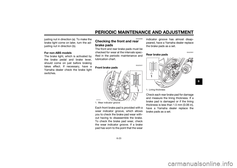
Front brake pads
Each front brake pad is provided with a
wear indicator groove, which allows
you to check the brake pad wear with-
out having to disassemble the brake.
To check the brake pad wear, check
the wear indicator groove. If a brake
pad has worn to the point that the wearindicator groove has almost disap-
peared, have a Yamaha dealer replace
the brake pads as a set.
EAU22501
Rear brake pads
Check each rear brake pad for damage
and measure the lining thickness. If a
brake pad is damaged or if the lining
thickness is less than 1.5 mm (0.06 in),
have a Yamaha dealer replace the
brake pads as a set.
1. Wear indicator grooveZAUM1180
1
1. Lining thickness
U5D7E5E0.book Page 23 Thursday, August 21, 2014 9:30 AM
Page 66 of 98
PERIODIC MAINTENANCE AND ADJUSTMENT
6-24
6
EAU40262
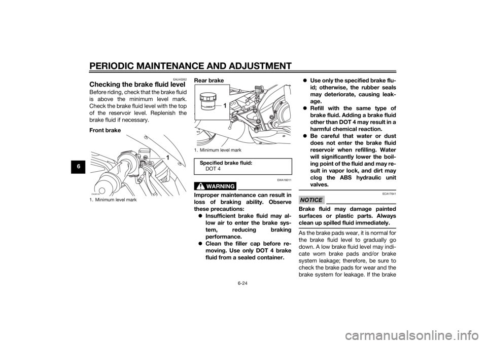
Checking the brake fluid levelBefore riding, check that the brake fluid
is above the minimum level mark.
Check the brake fluid level with the top
of the reservoir level. Replenish the
brake fluid if necessary.
Front brakeRear brake
WARNING
EWA16011
Improper maintenance can result in
loss of braking ability. Observe
these precautions:
Insufficient brake fluid may al-
low air to enter the brake sys-
tem, reducing braking
performance.
Clean the filler cap before re-
moving. Use only DOT 4 brake
fluid from a sealed container.Use only the specified brake flu-
id; otherwise, the rubber seals
may deteriorate, causing leak-
age.
Refill with the same type of
brake fluid. Adding a brake fluid
other than DOT 4 may result in a
harmful chemical reaction.
Be careful that water or dust
does not enter the brake fluid
reservoir when refilling. Water
will significantly lower the boil-
ing point of the fluid and may re-
sult in vapor lock, an
d dirt may
clog the ABS hydraulic unit
valves.
NOTICE
ECA17641
Brake fluid may damage painted
surfaces or plastic parts. Always
clean up spilled fluid immediately.As the brake pads wear, it is normal for
the brake fluid level to gradually go
down. A low brake fluid level may indi-
cate worn brake pads and/or brake
system leakage; therefore, be sure to
check the brake pads for wear and the
brake system for leakage. If the brake
1. Minimum level markZAUM1181
INFOINFO
1. Minimum level markSpecified brake fluid:
DOT 4
U5D7E5E0.book Page 24 Thursday, August 21, 2014 9:30 AM
Page 80 of 98
PERIODIC MAINTENANCE AND ADJUSTMENT
6-38
63. Remove the brake caliper by re-
moving the bolts. NOTICE: Do
not apply the brake after the
wheel and brake disc have been
removed, otherwise the brake
pads will be forced shut.
[ECA11073]
4. Pull the wheel axle out, and then
remove the wheel.
To install the front wheel
1. Lift the wheel up between the fork
legs.
2. Insert the wheel axle.
3. Lower the front wheel so that it is
on the ground.
4. Install the brake caliper by install-
ing the bolts.TIPMake sure that there is enough space
between the brake pads before install-
ing the brake caliper onto the brake
disc.5. Tighten the wheel axle to the
specified torque.
6. Tighten the wheel axle pinch bolt
A and pinch bolt B to the specified
torques.7. Retighten the wheel axle pinch
bolt A to the specified torque.
8. Tighten the brake caliper bolts to
the specified torques.
9. Push down hard on the handlebar
several times to check for proper
fork operation.
EAU44802
Rear wheel (for non-ABS
models)
WARNING
EWA14841
For the ABS model, have a Yamaha
dealer remove and install the wheel.
EAU56701
To remove the rear wheel
WARNING
EWA10822
To avoid injury, securely support the
vehicle so there is no danger of it
falling over.1. Loosen the axle nut.
Tightening torques:
Wheel axle:
59 Nm (5.9 m·kgf, 43 ft·lbf)
Front wheel axle pinch bolt:
23 Nm (2.3 m·kgf, 17 ft·lbf)
Brake caliper bolt:
38 Nm (3.8 m·kgf, 27 ft·lbf)
U5D7E5E0.book Page 38 Thursday, August 21, 2014 9:30 AM
Page 81 of 98
PERIODIC MAINTENANCE AND ADJUSTMENT
6-39
6
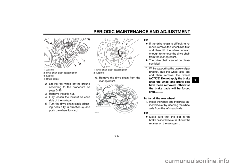
2. Lift the rear wheel off the ground
according to the procedure on
page 6-36.
3. Remove the axle nut.
4. Fully loosen the locknut on each
side of the swingarm.
5. Turn the drive chain slack adjust-
ing bolts fully in direction (a) and
push the wheel forward.6. Remove the drive chain from the
rear sprocket.
TIPIf the drive chain is difficult to re-
move, remove the wheel axle first,
and then lift the wheel upward
enough to remove the drive chain
from the rear sprocket.
The drive chain cannot be disas-
sembled.7. While supporting the brake caliper
bracket, pull the wheel axle out,
and then remove the wheel.
NOTICE: Do not apply the brake
after the wheel and brake disc
have been removed, otherwise
the brake pads will be forced
shut.
[ECA11073]
To install the rear wheel
1. Install the wheel and the brake cal-
iper bracket by inserting the wheel
axle from the left-hand side.TIPMake sure that the slot in the
brake caliper bracket is fit over the
retainer on the swingarm.
1. Axle nut
2. Drive chain slack adjusting bolt
3. Locknut
4. Brake caliperZAUM1193
1. Drive chain slack adjusting bolt
2. Locknut
(a)1
2
ZAUM1194
U5D7E5E0.book Page 39 Thursday, August 21, 2014 9:30 AM
Page 82 of 98

PERIODIC MAINTENANCE AND ADJUSTMENT
6-40
6Make sure that there is enough
space between the brake pads
before installing the wheel.
2. Install the drive chain onto the rear
sprocket.
3. Install the axle nut.
4. Lower the rear wheel so that it is
on the ground, and then put the
sidestand down.
5. Adjust the drive chain slack. (See
page 6-25.)
6. Tighten the axle nut, and then
tighten the locknuts to the speci-
fied torques.
EAU25872
TroubleshootingAlthough Yamaha motorcycles receive
a thorough inspection before shipment
from the factory, trouble may occur
during operation. Any problem in the
fuel, compression, or ignition systems,
for example, can cause poor starting
and loss of power.
The following troubleshooting charts
represent quick and easy procedures
for checking these vital systems your-
self. However, should your motorcycle
require any repair, take it to a Yamaha
dealer, whose skilled technicians have
the necessary tools, experience, and
know-how to service the motorcycle
properly.
Use only genuine Yamaha replace-
ment parts. Imitation parts may look
like Yamaha parts, but they are often
inferior, have a shorter service life and
can lead to expensive repair bills.
WARNING
EWA15142
When checking the fuel system, do
not smoke, and make sure there are
no open flames or sparks in the ar-
ea, including pilot lights from water
1. Retainer
2. Slot
Tightening torques:
Axle nut:
85 Nm (8.5 m·kgf, 61 ft·lbf)
Locknut:
16 Nm (1.6 m·kgf, 12 ft·lbf)
U5D7E5E0.book Page 40 Thursday, August 21, 2014 9:30 AM
Page 94 of 98

10-1
10
INDEXAABS (for ABS models) ........................... 3-14
ABS warning light (for ABS models) ....... 3-3
Air filter element and check hose,
replacing and cleaning ....................... 6-16
Auxiliary light bulb, replacing ................ 6-35BBattery .................................................. 6-31
Brake and clutch levers, checking and
lubricating ........................................... 6-28
Brake fluid, changing ............................ 6-25
Brake fluid level, checking .................... 6-24
Brake lever ............................................ 3-13
Brake light switches.............................. 6-22
Brake pedal........................................... 3-14
Brake pedal, checking and
lubricating ........................................... 6-29
Brake pedal free play, adjusting ........... 6-22CCables, checking and lubricating ......... 6-27
Care ........................................................ 7-1
Catalytic converter ................................ 3-17
Clutch lever ........................................... 3-13
Clutch lever free play, adjusting ........... 6-21
Coolant ................................................. 6-14
Cowlings and panel, removing and
installing................................................ 6-8DDimmer switch ...................................... 3-12
Drive chain, cleaning and lubricating .... 6-27
Drive chain slack................................... 6-25EEngine break-in....................................... 5-3
Engine idling speed, checking .............. 6-16Engine oil and oil filter element ............ 6-11
Engine stop switch ............................... 3-12
Engine trouble warning light ................... 3-3
FFront and rear brake pads, checking ... 6-23
Front brake lever free play, checking ... 6-22
Front fork, checking ............................. 6-30
Fuel ....................................................... 3-16
Fuel consumption, tips for reducing ...... 5-3
Fuel level warning light ........................... 3-2
Fuel tank cap ........................................ 3-15
Fuses, replacing ................................... 6-33HHandlebar switches .............................. 3-11
Headlight bulb, replacing ..................... 6-34
High beam indicator light ....................... 3-2
Horn switch .......................................... 3-12IIdentification numbers ............................ 9-1
Ignition circuit cut-off system ............... 3-19
Indicator lights and warning lights ......... 3-2
Info switch ............................................ 3-12LLicense plate light bulb, replacing........ 6-36MMain switch/steering lock....................... 3-1
Maintenance and lubrication, periodic ... 6-4
Maintenance, emission control
system.................................................. 6-3
Matte color, caution ............................... 7-1
Model label ............................................. 9-1
Multi-function meter unit ........................ 3-4NNeutral indicator light ............................. 3-2
PParking ....................................................5-4
Part locations ..........................................2-1
Pass switch ...........................................3-12RRider seat ..............................................3-18SSafety information ...................................1-1
Shifting ....................................................5-2
Shift pedal .............................................3-13
Sidestand ..............................................3-18
Sidestand, checking and lubricating.....6-29
Spark plug, checking ............................6-10
Specifications .........................................8-1
Starting the engine ..................................5-1
Start switch ...........................................3-12
Steering, checking ................................6-30
Storage ...................................................7-3
Supporting the motorcycle ...................6-36
Swingarm pivots, lubricating ................6-29TTail/brake light ......................................6-35
Throttle grip and cable, checking and
lubricating ...........................................6-28
Throttle grip free play, adjusting ...........6-17
Tires ......................................................6-18
Tool kit ....................................................6-2
Troubleshooting ....................................6-40
Troubleshooting charts .........................6-42
Turn signal indicator light........................3-2
Turn signal light bulb, replacing ............6-35
Turn signal switch .................................3-12VValve clearance .....................................6-17
U5D7E5E0.book Page 1 Thursday, August 21, 2014 9:30 AM