check engine YAMAHA YZF-R125 2016 User Guide
[x] Cancel search | Manufacturer: YAMAHA, Model Year: 2016, Model line: YZF-R125, Model: YAMAHA YZF-R125 2016Pages: 98, PDF Size: 6.87 MB
Page 36 of 98
For your safety – pre-operation checks
4-1
4
EAU63440
Inspect your vehicle each time you use it to make sure the vehicle is in safe oper-
ating condition. Always follow the inspection and maintenance procedures and
schedules described in the Owner’s Manual.
WARNING
EWA11152
Failure to inspect or maintain the vehicle properly increases the possibility
of an accident or equipment damage. Do not operate the vehicle if you find
any problem. If a problem cannot be corrected by the procedures provided
in this manual, have the vehicle inspected by a Yamaha dealer.
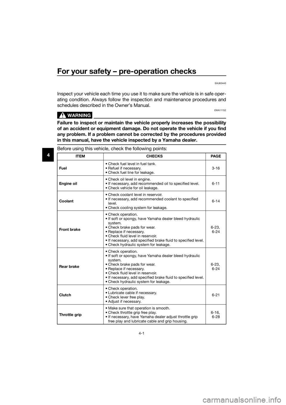
Before using this vehicle, check the following points:
ITEM CHECKS PAGE
Fuel• Check fuel level in fuel tank.
• Refuel if necessary.
• Check fuel line for leakage.3-16
Engine oil• Check oil level in engine.
• If necessary, add recommended oil to specified level.
• Check vehicle for oil leakage.6-11
Coolant• Check coolant level in reservoir.
• If necessary, add recommended coolant to specified
level.
• Check cooling system for leakage.6-14
Front brake• Check operation.
• If soft or spongy, have Yamaha dealer bleed hydraulic
system.
• Check brake pads for wear.
• Replace if necessary.
• Check fluid level in reservoir.
• If necessary, add specified brake fluid to specified level.
• Check hydraulic system for leakage.6-23,
6-24
Rear brake• Check operation.
• If soft or spongy, have Yamaha dealer bleed hydraulic
system.
• Check brake pads for wear.
• Replace if necessary.
• Check fluid level in reservoir.
• If necessary, add specified brake fluid to specified level.
• Check hydraulic system for leakage.6-23,
6-24
Clutch• Check operation.
• Lubricate cable if necessary.
• Check lever free play.
• Adjust if necessary.6-21
Throttle grip• Make sure that operation is smooth.
• Check throttle grip free play.
• If necessary, have Yamaha dealer adjust throttle grip
free play and lubricate cable and grip housing.6-16,
6-28
U5D7E6E0.book Page 1 Wednesday, June 17, 2015 10:25 AM
Page 39 of 98
Operation and important riding points
5-2
5
EAUM3530
Starting the engine
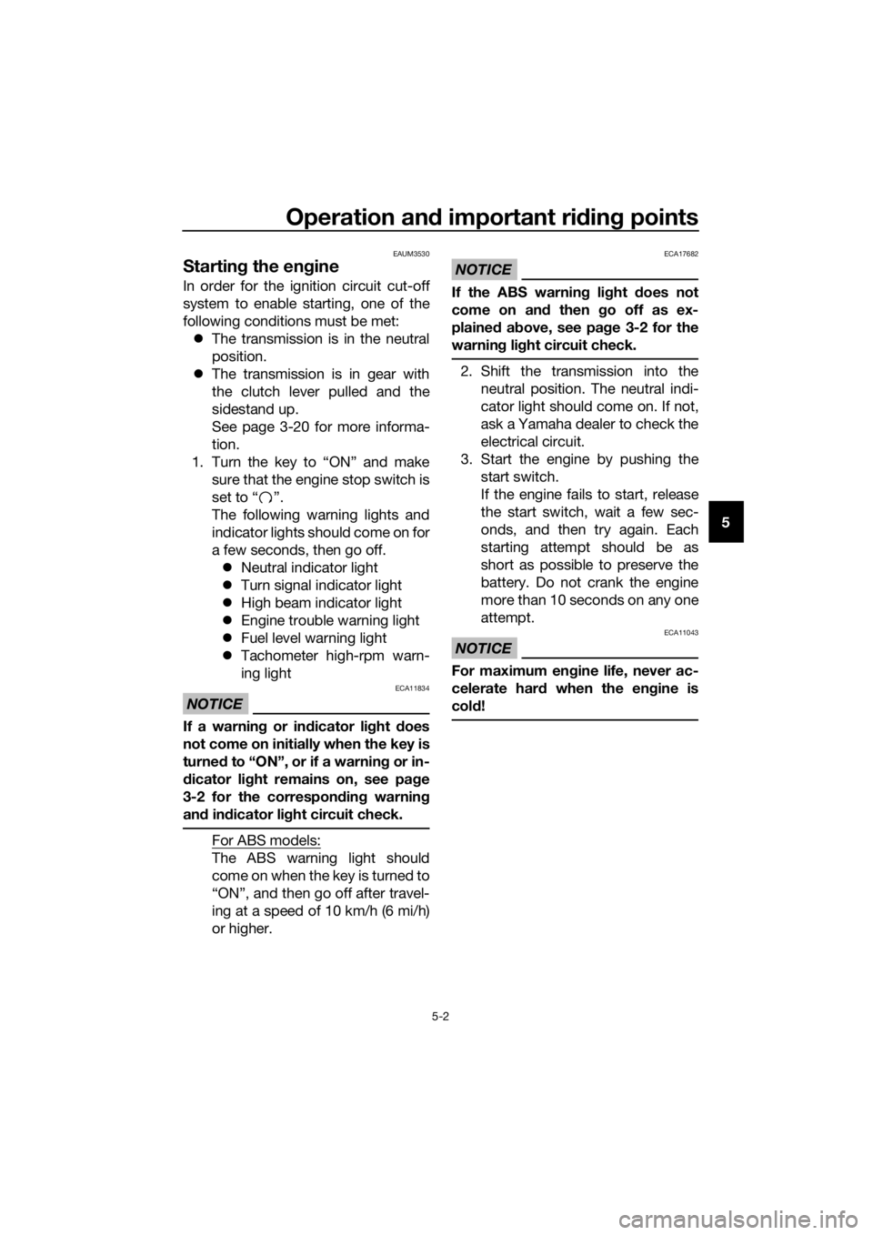
In order for the ignition circuit cut-off
system to enable starting, one of the
following conditions must be met:
The transmission is in the neutral
position.
The transmission is in gear with
the clutch lever pulled and the
sidestand up.
See page 3-20 for more informa-
tion.
1. Turn the key to “ON” and make
sure that the engine stop switch is
set to “ ”.
The following warning lights and
indicator lights should come on for
a few seconds, then go off.
Neutral indicator light
Turn signal indicator light
High beam indicator light
Engine trouble warning light
Fuel level warning light
Tachometer high-rpm warn-
ing light
NOTICE
ECA11834
If a warning or indicator light does
not come on initially when the key is
turned to “ON”, or if a warning or in-
dicator light remains on, see page
3-2 for the corresponding warning
and indicator light circuit check.
For ABS models:
The ABS warning light should
come on when the key is turned to
“ON”, and then go off after travel-
ing at a speed of 10 km/h (6 mi/h)
or higher.
NOTICE
ECA17682
If the ABS warning light does not
come on and then go off as ex-
plained above, see page 3-2 for the
warning light circuit check.
2. Shift the transmission into the
neutral position. The neutral indi-
cator light should come on. If not,
ask a Yamaha dealer to check the
electrical circuit.
3. Start the engine by pushing the
start switch.
If the engine fails to start, release
the start switch, wait a few sec-
onds, and then try again. Each
starting attempt should be as
short as possible to preserve the
battery. Do not crank the engine
more than 10 seconds on any one
attempt.
NOTICE
ECA11043
For maximum engine life, never ac-
celerate hard when the engine is
cold!
U5D7E6E0.book Page 2 Wednesday, June 17, 2015 10:25 AM
Page 42 of 98
Operation and important riding points
5-5
51000 km (600 mi) and beyond
The vehicle can now be operated nor-
mally.
NOTICE
ECA10311
Keep the engine speed out of
the tachometer red zone.
If any engine trouble should oc-
cur during the engine break-in
period, immediately have a
Yamaha dealer check the vehi-
cle.
EAU17214
Parking
When parking, stop the engine, and
then remove the key from the main
switch.
WARNING
EWA10312
Since the engine and exhaust
system can become very hot,
park in a place where pedestri-
ans or children are not likely to
touch them and be burned.
Do not park on a slope or on soft
ground, otherwise the vehicle
may overturn, increasing the
risk of a fuel leak and fire.
Do not park near grass or other
flammable materials which
might catch fire.
U5D7E6E0.book Page 5 Wednesday, June 17, 2015 10:25 AM
Page 45 of 98

Periodic maintenance and adjustment
6-3
6
EAU46872
TIP
The annual checks must be performed every year, except if a kilometer-
based maintenance, or for the UK, a mileage-based maintenance, is
performed instead.
From 30000 km (17500 mi), repeat the maintenance intervals starting from
6000 km (3500 mi).
Items marked with an asterisk should be performed by a Yamaha dealer as
they require special tools, data and technical skills.
EAU69210
Periodic maintenance chart for the emission control system
NO. ITEM
1*Fuel line• Check fuel hoses for cracks or
damage.√√√√√
2Spark plug• Check condition.
• Clean and regap.√√
• Replace.√√
3*Va l ve s• Check valve clearance.
•Adjust.√√√√
4*Fuel injection• Check engine idle speed.√√√√√X 1000 km CHECK OR
MAINTENANCE JOB
X 1000 mi
ODOMETER
READING
ANNUAL CHECK
16121824
0.63.5710.514
U5D7E6E0.book Page 3 Wednesday, June 17, 2015 10:25 AM
Page 47 of 98

Periodic maintenance and adjustment
6-5
6
13 Drive chain• Check chain slack, alignment
and condition.
• Adjust and lubricate chain with a
special O-ring chain lubricant
thoroughly.Every 1000 km (600 mi) and af-
ter washing the motorcycle, rid-
ing in the rain or riding in wet
areas
14*Steering bearings• Check bearing play and steering
for roughness.√√√√√
• Lubricate with lithium-soap-
based grease.Every 24000 km (14000 mi)
15*Chassis fasteners• Make sure that all nuts, bolts
and screws are properly tight-
ened.√√√√√
16Brake lever pivot
shaft• Lubricate with silicone grease.√√√√√
17Brake pedal pivot
shaft• Lubricate with lithium-soap-
based grease.√√√√√
18Clutch lever pivot
shaft• Lubricate with lithium-soap-
based grease.√√√√√
19 Sidestand• Check operation.
• Lubricate with lithium-soap-
based grease.√√√√√
20*Sidestand switch• Check operation.√√√√√√
21*Front fork• Check operation and for oil leak-
age.√√√√
22*Shock absorber
assembly• Check operation and shock ab-
sorber for oil leakage.√√√√
23*Rear suspension
relay arm and con-
necting arm pivot-
ing points• Check operation.√√√√
• Lubricate with lithium-soap-
based grease.
√√
24 Engine oil• Change. (See pages 3-9 and
6-11.)√When the oil change indi-
cator light flashes (2000
km (1200 mi) after the ini-
tial 1000 km [600 mi] and
every 3000 km (1800 mi)
thereafter)
• Check oil level and vehicle for oil
leakage.Every 3000 km (1800 mi)√ NO. ITEM
X 1000 km CHECK OR
MAINTENANCE JOB
X 1000 mi
ODOMETER
READING
ANNUAL CHECK
16121824
0.63.5710.514
U5D7E6E0.book Page 5 Wednesday, June 17, 2015 10:25 AM
Page 48 of 98

Periodic maintenance and adjustment
6-6
6
EAUM2071
TIP
The air filter needs more frequent service if you are riding in unusually wet or
dusty areas.
Hydraulic brake service
• Regularly check and, if necessary, correct the brake fluid level.
• Every two years change the brake fluid.
• Replace the brake hoses every four years and if cracked or damaged.
25Engine oil filter el-
ement• Replace.√√√√√
26*Cooling system• Check coolant level and vehicle
for coolant leakage.√√√√√
• Change coolant. Every 3 years
27*Front and rear
brake switches• Check operation.√√√√√√
28Moving parts and
cables• Lubricate.√√√√√
29*Throttle grip• Check operation.
• Check throttle grip free play, and
adjust if necessary.
• Lubricate cable and grip hous-
ing.√√√√√
30*Lights, signals and
switches• Check operation.
• Adjust headlight beam.√√√√√√ NO. ITEM
X 1000 km CHECK OR
MAINTENANCE JOB
X 1000 miODOMETER
READING
ANNUAL CHECK
16121824
0.6 3.5 7 10.5 14
U5D7E6E0.book Page 6 Wednesday, June 17, 2015 10:25 AM
Page 51 of 98
Periodic maintenance and adjustment
6-9
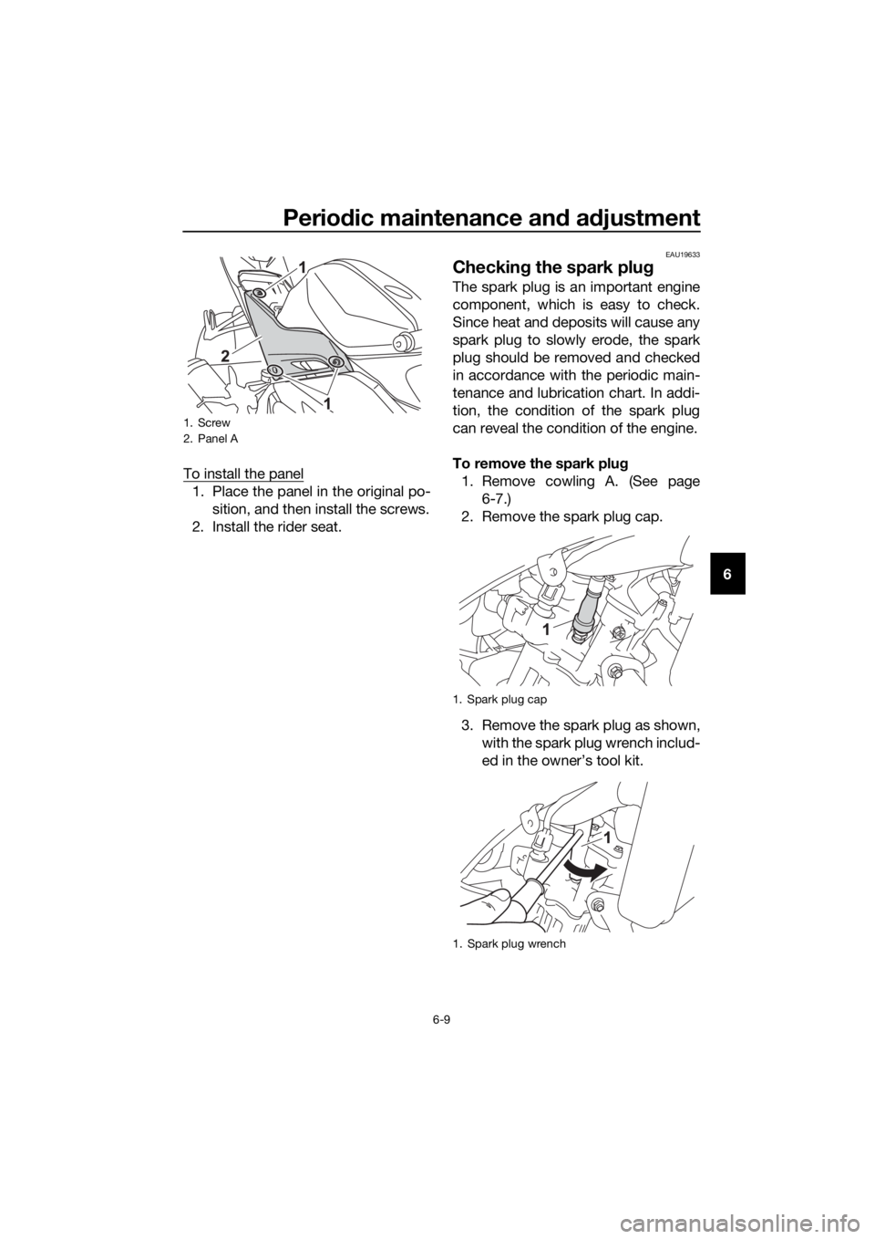
6 To install the panel
1. Place the panel in the original po-
sition, and then install the screws.
2. Install the rider seat.
EAU19633
Checking the spark plug
The spark plug is an important engine
component, which is easy to check.
Since heat and deposits will cause any
spark plug to slowly erode, the spark
plug should be removed and checked
in accordance with the periodic main-
tenance and lubrication chart. In addi-
tion, the condition of the spark plug
can reveal the condition of the engine.
To remove the spark plug
1. Remove cowling A. (See page
6-7.)
2. Remove the spark plug cap.
3. Remove the spark plug as shown,
with the spark plug wrench includ-
ed in the owner’s tool kit.
1. Screw
2. Panel A
1. Spark plug cap
1. Spark plug wrench
U5D7E6E0.book Page 9 Wednesday, June 17, 2015 10:25 AM
Page 52 of 98
Periodic maintenance and adjustment
6-10
6To check the spark plug
1. Check that the porcelain insulator
around the center electrode of the
spark plug is a medium-to-light
tan (the ideal color when the vehi-
cle is ridden normally).
TIP
If the spark plug shows a distinctly dif-
ferent color, the engine could be oper-
ating improperly. Do not attempt to
diagnose such problems yourself. In-
stead, have a Yamaha dealer check
the vehicle.
2. Check the spark plug for electrode
erosion and excessive carbon or
other deposits, and replace it if
necessary.
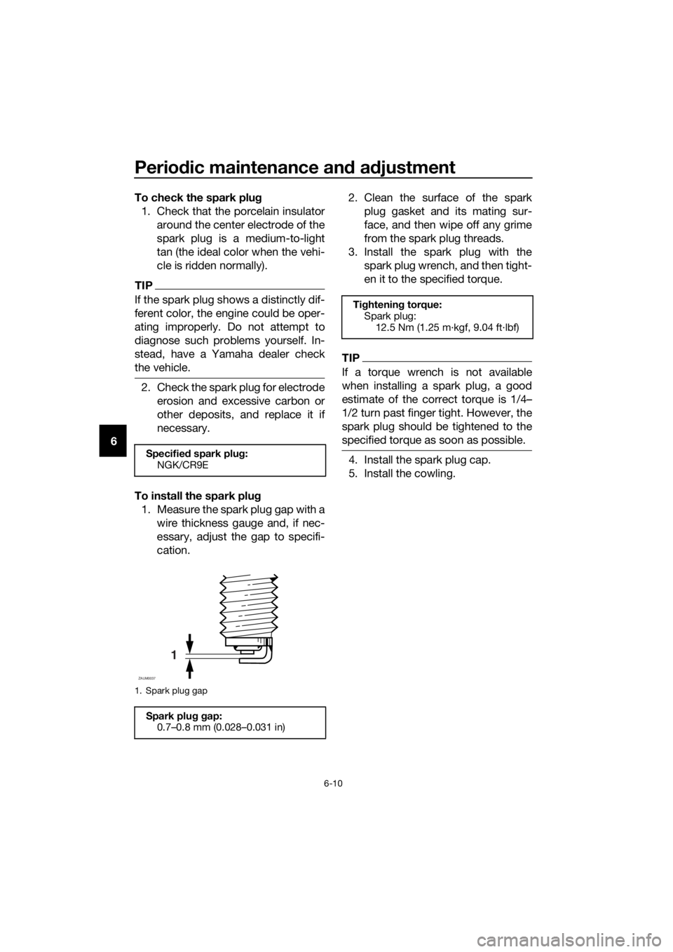
To install the spark plug
1. Measure the spark plug gap with a
wire thickness gauge and, if nec-
essary, adjust the gap to specifi-
cation.2. Clean the surface of the spark
plug gasket and its mating sur-
face, and then wipe off any grime
from the spark plug threads.
3. Install the spark plug with the
spark plug wrench, and then tight-
en it to the specified torque.
TIP
If a torque wrench is not available
when installing a spark plug, a good
estimate of the correct torque is 1/4…
1/2 turn past finger tight. However, the
spark plug should be tightened to the
specified torque as soon as possible.
4. Install the spark plug cap.
5. Install the cowling.Specified spark plug:
NGK/CR9E
1. Spark plug gap
Spark plug gap:
0.7–0.8 mm (0.028–0.031 in)
1
ZAUM0037
Tightening torque:
Spark plug:
12.5 Nm (1.25 m·kgf, 9.04 ft·lbf)
U5D7E6E0.book Page 10 Wednesday, June 17, 2015 10:25 AM
Page 53 of 98
Periodic maintenance and adjustment
6-11
6
EAUM3491
Engine oil and oil filter ele-
ment
The engine oil level should be checked
before each ride. In addition, the oil
must be changed and the oil filter ele-
ment replaced at the intervals specified
in the periodic maintenance and lubri-
cation chart.
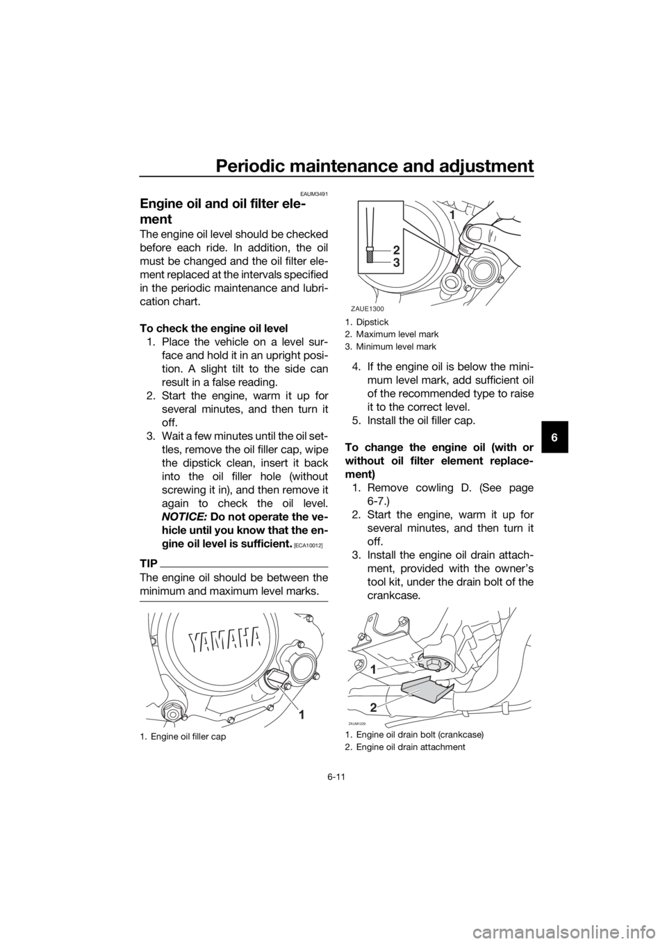
To check the engine oil level
1. Place the vehicle on a level sur-
face and hold it in an upright posi-
tion. A slight tilt to the side can
result in a false reading.
2. Start the engine, warm it up for
several minutes, and then turn it
off.
3. Wait a few minutes until the oil set-
tles, remove the oil filler cap, wipe
the dipstick clean, insert it back
into the oil filler hole (without
screwing it in), and then remove it
again to check the oil level.
NOTICE: Do not operate the ve-
hicle until you know that the en-
gine oil level is sufficient.
[ECA10012]
TIP
The engine oil should be between the
minimum and maximum level marks.
4. If the engine oil is below the mini-
mum level mark, add sufficient oil
of the recommended type to raise
it to the correct level.
5. Install the oil filler cap.
To change the engine oil (with or
without oil filter element replace-
ment)
1. Remove cowling D. (See page
6-7.)
2. Start the engine, warm it up for
several minutes, and then turn it
off.
3. Install the engine oil drain attach-
ment, provided with the owner’s
tool kit, under the drain bolt of the
crankcase.
1. Engine oil filler cap
1. Dipstick
2. Maximum level mark
3. Minimum level mark
1. Engine oil drain bolt (crankcase)
2. Engine oil drain attachment
1
2
3
ZAUE1300
ZAUM1229
2
U5D7E6E0.book Page 11 Wednesday, June 17, 2015 10:25 AM
Page 55 of 98
![YAMAHA YZF-R125 2016 User Guide Periodic maintenance and adjustment
6-13
6 NOTICE: Before installing the
engine oil drain bolt, do not for-
get to install the O-ring, com-
pression spring, and oil strainer
in position.
[ECA10422]
1 YAMAHA YZF-R125 2016 User Guide Periodic maintenance and adjustment
6-13
6 NOTICE: Before installing the
engine oil drain bolt, do not for-
get to install the O-ring, com-
pression spring, and oil strainer
in position.
[ECA10422]
1](/img/51/54258/w960_54258-54.png)
Periodic maintenance and adjustment
6-13
6 NOTICE: Before installing the
engine oil drain bolt, do not for-
get to install the O-ring, com-
pression spring, and oil strainer
in position.
[ECA10422]
11. Refill with the specified amount of
the recommended engine oil, and
then install and tighten the oil filler
cap.
NOTICE
ECA11621
In order to prevent clutch slip-
page (since the engine oil also
lubricates the clutch), do not
mix any chemical additives. Do
not use oils with a diesel speci-
fication of “CD” or oils of a high-
er quality than specified. In
addition, do not use oils labeled
“ENERGY CONSERVING II” or
higher.
Make sure that no foreign mate-
rial enters the crankcase.
12. Start the engine, and then let it idle
for several minutes while checking
it for oil leakage. If oil is leaking,
immediately turn the engine off
and check for the cause.13. Turn the engine off, and then
check the oil level and correct it if
necessary.
14. Reset the oil change indicator.
(See page 3-9.)
Tightening torques:
Engine oil drain bolt:
32 Nm (3.2 m·kgf, 23 ft·lbf)
Recommended engine oil:
See page 8-1.
Oil quantity:
Without oil filter element replace-
ment:
0.95 L (1.00 US qt, 0.84 Imp.qt)
With oil filter element replacement:
1.00 L (1.06 US qt, 0.88 Imp.qt)
U5D7E6E0.book Page 13 Wednesday, June 17, 2015 10:25 AM