YAMAHA YZF-R1M 2020 Owner's Manual
Manufacturer: YAMAHA, Model Year: 2020, Model line: YZF-R1M, Model: YAMAHA YZF-R1M 2020Pages: 136, PDF Size: 16.15 MB
Page 21 of 136

Special features
3-4
3
Decelerating and throttle fully-
closed
TIPQS and QS can be individ-
ually set.
Shifting into or out of neutral must
be done using the clutch lever.LIF
The lift control system reduces the rate
at which the front wheel will continue to
rise during extreme acceleration, such
as during starts or out-of-corner exits.
When front-wheel lift is detected, en-
gine power is regulated to slow front-
wheel lift while still providing good ac-
celeration.
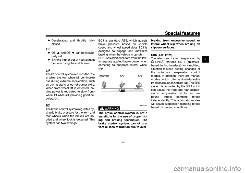
BC
The brake control system regulates hy-
draulic brake pressure for the front and
rear wheels when the brakes are ap-
plied and wheel lock is detected. This
system has two settings. BC1 is standard ABS, which adjusts
brake pressure based on vehicle
speed and wheel speed data. BC1 is
designed to engage and maximize
braking when the vehicle is upright.
BC2 uses additional data from the IMU
to regulate applied brake power when
cornering to suppress lateral wheel
slip.
WARNING
EWA20891
The
brake control system is not a
su bstitute for the use of proper ri d-
in g an d brakin g techniques. The
b rake control system cannot pre-
vent all loss of traction due to over- b
rakin g from excessive spee d, or
lateral wheel slip when brakin g on
slippery surfaces.
ERS (YZF-R1M)
The electronic racing suspension by
ÖHLINS
® features OBTi (objective-
based tuning interface) for simplified,
situation-focused setting changes of
the automatic suspension control
modes. In addition, there are manual
modes which offer a finely-tuneable
traditional suspension set-up. The ERS
system is controlled by the SCU which
can adjust the front and rear suspen-
sion’s compression stroke and re-
bound stroke damping forces
independently. The automatic modes
will adjust suspension damping forces
based on running conditions.
ABS
BC1/BC2 BC2 BC2
UB3LE0E0.book Page 4 Tuesday, July 23, 2019 12:05 PM
Page 22 of 136

Special features
3-5
3
EAU66313
GlossaryABS - Anti-lock Brake System
ABS ECU - Anti-lock Brake System
Electronic Control Unit
BC - Brake Control
CCU - Communication Control Unit
EBM - Engine Brake Management
ECU - Engine Control Unit
ERS - Electronic Racing Suspension
GPS - Global Positioning System
IMU - Inertial Measurement Unit
LCS - Launch Control System
LIF - Lift Control System
PWR - Power delivery mode
QS - Quick Shift
QSS - Quick Shift System
SC - Stability Control
SCS - Slide Control System
SCU - Suspension Control Unit
TCS - Traction Control System
YRC - Yamaha Ride ControlUB3LE0E0.book Page 5 Tuesday, July 23, 2019 12:05 PM
Page 23 of 136

Special features
3-6
3
EAU66911
YRC functions visual gui de
BC2
BC1/BC2 EBM
1. Start
2. Acceleration
3. Braking
4. Apex
5. Exit
6. Straightaway
UB3LE0E0.book Page 6 Tuesday, July 23, 2019 12:05 PM
Page 24 of 136

Instrument and control functions
4-1
4
EAU1097A
Immo bilizer systemThis vehicle is equipped with an immo-
bilizer system to help prevent theft by
re-registering codes in the standard
keys. This system consists of the fol-
lowing:
a code re-registering key
two standard keys
a transponder (in each key)
an immobilizer unit (on the vehicle)
an ECU (on the vehicle)
a system indicator light (page 4-7) A
bout the keys
The code re-registering key acts like a
master key. It is used to register codes
in each standard key. Store the code
re-registering key in a safe place. Use
a standard key for daily operation.
When key replacement or re-register-
ing is necessary, bring the vehicle and
the master key along with any remain-
ing standard keys to a Yamaha dealer
to have them re-registered.
TIP Keep the standard keys as well as
keys of other immobilizer systems
away from the code re-registering
key.
Keep other immobilizer system
keys away from the main switch
as they may cause signal interfer-
ence.NOTICE
ECA11823
DO NOT LOSE THE CODE RE-REG-
ISTERING KEY! CONTACT YOUR
DEALER IMMEDIATELY IF IT IS
LOST! If the cod e re-registering key
is lost, the existin g stan dar d keys
can still be used to start the vehicle. However, re
gisterin g a new stan-
d ar d key is impossi ble. If all keys
have been lost or damag ed , the en-
tire immo bilizer system must be re-
place d. Therefore, han dle the keys
carefully. Do not su bmerse in water.
Do not expose to hi gh tempera-
tures.
Do not place near ma gnets.
Do not place near items that
transmit electrical si gnals.
Do not han dle rou ghly.
Do not grin d or alter.
Do not disassem ble.
Do not put two keys of any im-
mo bilizer system on the same
key rin g.
1. Code re-registering key (red bow)
2. Standard keys (black bow)UB3LE0E0.book Page 1 Tuesday, July 23, 2019 12:05 PM
Page 25 of 136

Instrument and control functions
4-2
4
EAU10474
Main switch/steerin g lockThe main switch/steering lock controls
the ignition and lighting systems, and is
used to lock the steering. The various
positions are described below.TIPBe sure to use the standard key (black
bow) for regular use of the vehicle. To
minimize the risk of losing the code re-
registering key (red bow), keep it in a
safe place and only use it for code re-
registering.
EAU84031
ON
All electrical circuits are supplied with
power and the vehicle lights are turned
on. The engine can be started. The key
cannot be removed.TIP The headlight(s) will turn on when
the engine is started.
To prevent battery drain, do not
leave the key in the on position
without the engine running.
EAU10662
OFF
All electrical systems are off. The key
can be removed.
WARNING
EWA10062
Never turn the key to “OFF” or
“LOCK” while the vehicle is movin g.
Otherwise the electrical systems will
b e switched off, which may result in
loss of control or an acci dent.
EAU73800
LOCK
The steering is locked and all electrical
systems are off. The key can be re-
moved.
To lock the steering1. Turn the handlebars all the way to
the left.
2. With the key in the “OFF” position, push the key in and turn it to
“LOCK”.
3. Remove the key.
ON
OFF
LOCK
1. Push.
2. Turn.12
UB3LE0E0.book Page 2 Tuesday, July 23, 2019 12:05 PM
Page 26 of 136

Instrument and control functions
4-3
4
TIPIf the steering will not lock, try turning
the handlebars back to the right slight-
ly.To unlock the steeringPush the key in and turn it to “OFF”.
EAU66055
Han dle bar switchesLeft
Right
1. Push.
2. Turn.12
1. Pass/LAP switch “ /LAP”
2. Dimmer switch “ / ”
3. Hazard switch “OFF/ ”
4. Horn switch “ ”
5. Turn signal switch “ / ”
1
2
54 3
1. Mode switch “MODE”
2. Up button
3. Center button
4. Down button
1. Stop/Run/Start switch “ / / ”
2. Wheel switch “ ”
1 2
3
4
1
2
UB3LE0E0.book Page 3 Tuesday, July 23, 2019 12:05 PM
Page 27 of 136

Instrument and control functions
4-4
4
EAU66091
Pass/LAP switch “ /LAP”
Press this switch to flash the head-
lights and to mark the start of each lap
when using the lap timer.
EAU79872
Dimmer switch “ / ”
Set this switch to “ ” for the high
beam and to “ ” for the low beam.TIPWhen the switch is set to low beam,
only the left headlight comes on. When
the switch is set to high beam, both
headlights come on.
EAU66040
Turn si gnal switch “ / ”
To signal a right-hand turn, push this
switch to “ ”. To signal a left-hand
turn, push this switch to “ ”. When
released, the switch returns to the cen-
ter position. To cancel the turn signal
lights, push the switch in after it has re-
turned to the center position.
EAU66030
Horn switch “ ”
Press this switch to sound the horn.
EAU66060
Stop/Run/Start switch “ / / ”
To crank the engine with the starter,
set this switch to “ ”, and then push
the switch down towards “ ”. See
page 6-2 for starting instructions prior
to starting the engine.
Set this switch to “ ” to stop the en-
gine in case of an emergency, such as
when the vehicle overturns or when the
throttle cable is stuck.
EAU88272
Hazar d switch “OFF/ ”
Use this switch to turn on the hazard
lights (simultaneous flashing of all turn
signal lights). The hazard lights are
used in case of an emergency or to
warn other drivers when your vehicle is
stopped where it might be a traffic haz-
ard.
The hazard lights can be turned on or
off only when the key is in the “ON” po-
sition. You can turn the main switch to
the “OFF” or “LOCK” position, and the
hazard lights will continue to flash. To
turn off the hazard lights, turn the main
switch to the “ON” position and oper-
ate the hazard switch again.
NOTICE
ECA10062
Do not use the hazar d lig hts for an
exten ded len gth of time with the en-
g ine not runnin g, otherwise the bat-
tery may d ischarge.
EAU88400
Mo de switch “MODE”
Use the mode switch to change YRC
modes or edit the PWR, TCS, SCS,
and EBM settings from the main
screen. This switch has three buttons.
Up button - push this button to
change the selected YRC setting up-
ward.
Center button - push this button to
scroll left to right among the MODE,
PWR, TCS, SCS, and EBM items.
Down button - push this button to
change the selected YRC setting
downward.TIP The center button is also used to
activate the launch control sys-
tem. When the LCS icon is grey,
push and hold the center button.
UB3LE0E0.book Page 4 Tuesday, July 23, 2019 12:05 PM
Page 28 of 136

Instrument and control functions
4-5
4 The LCS icon will flash and turn
white when the system has been
activated.
The traction control system can
only be turned off from the main
screen. Select TCS with the center
button, then push and hold the up
button until TCS OFF is displayed.
To turn the traction control system
back on, use the down button.
When TCS has been turned off,
the SCS, LCS, and LIF systems
are also turned off for all YRC
modes.
See “YRC Setting” on page 4-16
for more information on how to
customize YRC modes and adjust
YRC item setting levels.
EAU66100
Wheel switch “ ”
When the main screen is set to
STREET MODE, use the wheel switch
to scroll and reset the information dis-
play items.
When the main screen is set to TRACK
MODE, use the wheel switch to scroll
and reset the information display items
and to activate the lap timer. When the display has been changed to
the MENU screen, use the wheel
switch to navigate the setting modules
and make setting changes.
Operate the wheel switch as follows.
Rotate up
- rotate the wheel upward to
scroll up/left or increase a setting val-
ue.
Rotate down - rotate the wheel down-
ward to scroll down/right or decrease a
setting value.
Short push - briefly press the switch
inward to make and confirm selec-
tions.
Lon g push - press the switch inward
for one second to reset an information
display item or to access and exit the
MENU screen.
TIP See page 4-9 for more information
on the main screen and its func-
tions.
See page 4-15 for more informa-
tion on the MENU screen and how
to make setting changes.
EAU4939H
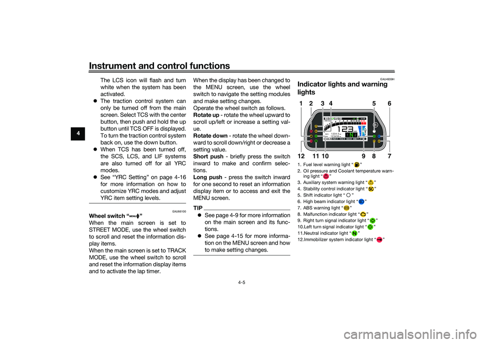
Indicator li ghts an d warnin g
li g hts1. Fuel level warning light “ ”
2. Oil pressure and Coolant temperature warn-
ing light “ ”
3. Auxiliary system warning light “ ”
4. Stability control indicator light “ ”
5. Shift indicator light “ ”
6. High beam indicator light “ ”
7. ABS warning light “ ”
8. Malfunction indicator light “ ”
9. Right turn signal indicator light “ ”
10.Left turn signal indicator light “ ”
11.Neutral indicator light “ ”
12.Immobilizer system indicator light “ ”
ABS
1 2
GPSN
LCSQS
LIF 2
ODO123456 TRIP-1
1234.5
1000 r/min
km
km
km/h
10:
00
MODE-APWR 1TCS 3SCS 2EBM 1T-2
5
12
6
7
9
8
1012
11
3
4
UB3LE0E0.book Page 5 Tuesday, July 23, 2019 12:05 PM
Page 29 of 136

Instrument and control functions
4-6
4
EAU88280
Turn si gnal in dicator li ghts “ ”
an d“”
Each indicator light will flash when its
corresponding turn signal lights are
flashing.
EAU88300
Neutral in dicator li ght “ ”
This indicator light comes on when the
transmission is in the neutral position.
EAU88310
Hi gh beam in dicator li ght “ ”
This indicator light comes on when the
high beam of the headlight is switched
on.
EAU88320
Fuel level warnin g li ght “ ”
This warning light comes on when the
fuel level drops below approximately
3.0 L (0.79 US gal, 0.66 Imp.gal). When
this occurs, refuel as soon as possible.
The electrical circuit of the warning
light can be checked by turning the ve-
hicle on. The warning light should
come on for a few seconds, and then
go off.
TIPIf the warning light does not come on at
all, remains on after refueling, or if the
warning light flashes repeatedly, have
a Yamaha dealer check the vehicle.
EAU88330
Malfunction in dicator li ght
(MIL) “ ”
This light comes on or flashes if a prob-
lem is detected in the engine or other
vehicle control system. If this occurs,
have a Yamaha dealer check the on-
board diagnostic system. The electri-
cal circuit of the warning light can be
checked by vehicle power on. The light
should come on for a few seconds,
and then go off. If the light does not
come on initially when the vehicle pow-
er on, or if the light remains on, have a
Yamaha dealer check the vehicle.NOTICE
ECA26820
If the MIL starts flashin g, re duce en-
g ine spee d to prevent exhaust sys-
tem damag e.
TIPThe engine is sensitively controlled for
the on-board diagnostic system to de-
tect deterioration and malfunction of
the emission control system. Due to
this specification, the MIL may come
on or flash for vehicle modifications,
lack of maintenance, or excessive or
improper use of the motorcycle. To
prevent this, observe these precau-
tions.
Do not attempt to modify the soft-
ware of the engine control unit.
Do not add any electrical acces-
sories that interfere with engine
control.
Do not use aftermarket accesso-
ries or parts such as suspension,
spark plugs, injectors, exhaust
system, etc.
Do not change drivetrain specifi-
cations (chain, sprockets, wheels,
tires, etc.).
Do not remove or alter the O2 sen-
sor, air induction system, or ex-
haust parts (catalysts or EXUP,
etc.).
Maintain proper drive chain.
UB3LE0E0.book Page 6 Tuesday, July 23, 2019 12:05 PM
Page 30 of 136

Instrument and control functions
4-7
4
Maintain correct tire pressure.
Maintain proper brake pedal
height to prevent rear brake from
dragging.
Do not operate the vehicle in an
extreme manner. For example, re-
peated or excessive opening and
closing of the throttle, racing,
burnouts, wheelies, extended
half-clutch use, etc.
EAU88342
ABS warnin g li ght “ ”
In normal operation, the ABS warning
light comes on when the vehicle is
turned on, and goes off after traveling
at a speed of 10 km/h (6 mi/h) or high-
er.TIPIf the warning light does not work as
described above, or if the warning light
comes on while riding, the ABS may
not work correctly. Have a Yamaha
dealer check the vehicle as soon as
possible.
WARNING
EWA16043
If the ABS warnin g lig ht does not
turn off after reachin g 10 km/h (6
mi/h), or if the warnin g li ght comes
on while ri din g:
Use extra caution to avoi d pos-
si ble wheel lock durin g emer-
g ency brakin g.
Have a Yamaha dealer check
the vehicle as soon as possi ble.
EAU67433
Shift in dicator li ght “ ”
This indicator light comes on when it is
time to shift to the next higher gear.
The engine speeds at which it comes
on or goes off can be adjusted. (See
page 4-25.)TIPWhen the vehicle is turned on, this light
should come on for a few seconds and
then go off. If the light does not come
on, or if the light remains on, have a
Yamaha dealer check the vehicle.
EAU88350
Immo bilizer system in dicator
li g ht “ ”
When the main switch is turned off and
30 seconds have passed, the indicator
light will flash steadily to indicate the
immobilizer system is enabled. After 24
hours have passed, the indicator light
will stop flashing, however the immobi-
lizer system is still enabled.TIPWhen the vehicle is turned on, this light
should come on for a few seconds and
then go off. If the light does not come
on, or if the light remains on, have a
Yamaha dealer check the vehicle.Transpon der interference
If the immobilizer system indicator light
flashes in the pattern, slowly 5 times
then quickly 2 times, this could be
caused by transponder interference. If
this occurs, try the following. 1. Make sure there are no other im- mobilizer keys close to the main
switch.
2. Use the code re-registering key to start the engine.
UB3LE0E0.book Page 7 Tuesday, July 23, 2019 12:05 PM