brake YAMAHA YZF-R1M 2022 User Guide
[x] Cancel search | Manufacturer: YAMAHA, Model Year: 2022, Model line: YZF-R1M, Model: YAMAHA YZF-R1M 2022Pages: 136, PDF Size: 6.01 MB
Page 33 of 136
Instrument and control functions
4-10
4
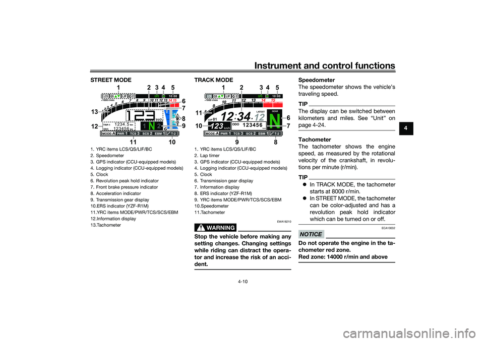
STREET MODE TRACK MODE
WARNING
EWA18210
Stop the vehicle
before makin g any
settin g chan ges. Chan gin g settin gs
while ri din g can distract the opera-
tor an d increase the risk of an acci-
d ent.
Speed ometer
The speedometer shows the vehicle’s
traveling speed.TIPThe display can be switched between
page 4-24.Tachometer
The tachometer shows the engine
speed, as measured by the rotational
velocity of the crankshaft, in revolu-
tions per minute (r/min).TIP In TRACK MODE, the tachometer
starts at 8000 r/min.
In STREET MODE, the tachometer
can be color-adjusted and has a
revolution peak hold indicator
which can be turned on or off.NOTICE
ECA10032
Do not operate the en gine in the ta-
chometer red zone.
Re d zone: 14000 r/min an d a bove
1. YRC items LCS/QS/LIF/BC
2. Speedometer
3. GPS indicator (CCU-equipped models)
4. Logging indicator (CCU-equipped models)
5. Clock
6. Revolution peak hold indicator
7. Front brake pressure indicator
8. Acceleration indicator
9. Transmission gear display
10.ERS indicator (YZF-R1M)
11.YRC items MODE/PWR/TCS/SCS/EBM
12.Information display
13.Tachometer
1
2
GPS
N
LCS
QS
LIF 2
ODO
123456
TRIP-1
1234.5
1000 r/min
km
km
km/h
10:
00
MODE-
APWR
1
TCS
3
SCS
2
EBM
1
T-2
6
11 978
3
1
10
25
4
13
12
1. YRC items LCS/QS/LIF/BC
2. Lap timer
3. GPS indicator (CCU-equipped modelsF
4. Logging indicator (CCU-equipped modelsF
5. Clock
6. Transmission gear display
7. Information display
8. ERS indicator (YZF-R1MF
9. YRC items MODE/PWR/TCS/SCS/EBM
10.Speedometer
11.Tachometer
N
12
12 34
LAP 01
ODO
km
123456
LATEST
1000 r/min
km/h
123
km/h
123
GEAR
GPS
LCS
QS
LIF
10
:
00
MODE-
APWR
1
TCS
3
SCS
2
EBM
1
T-2
29
1
8
1110
2
6
7
3
5
4
UB3LE1E0.book Page 10 Tuesday, August 10, 2021 2:28 PM
Page 34 of 136
Instrument and control functions
4-11
4 Information
display
This section of the main screen is used
to show additional riding related infor-
mation such as air and coolant temper-
ature readings, tripmeters, and fuel
consumption statistics. The informa-
tion display items can be set into four
groups via the MENU screen.
The information display items are:
A.TEMP: air temperature
C.TEMP: coolant temperature
TRIP-1: tripmeter 1
TRIP-2: tripmeter 2
F-TRIP: fuel tripmeter
ODO: odometer
FUEL CON: the amount of fuel con-
sumed
FUEL AVG: average fuel consumption
CRNT FUEL: current fuel consumption
TIP ODO will lock at 999999 and can-
not be reset.
TRIP-1 and TRIP-2 will reset to 0
and begin counting again after
9999.9 has been reached.
When the fuel tank reserve level
has been reached, F-TRIP ap-
pears automatically and begins
recording distance traveled from
that point.
After refueling and traveling some
distance, F-TRIP will automatically
disappear.
See “Unit” on page 4-24 to chan-
ge the fuel consumption units.
The air temperature displayed
may vary from the actual ambient
temperature.
In TRACK MODE, information dis-
play items FASTEST (fastest lap
time) and AVERAGE (average lap
time) are also available.
TRIP-1, TRIP-2, F-TRIP, FUEL CON,
and FUEL AVE items can be individual-
ly reset.
To reset information display items1. Use the wheel switch to scroll
through the display items until the
item you want to reset appears.
2. Short push the wheel switch and the item will flash for five seconds.
(For STREET MODE, if both items are resettable items, the top item
will flash first. Scroll down to se-
lect the bottom item.)
3. While the item is flashing, press and hold the wheel switch for one
second.
Transmission gear display
This shows which gear the transmis-
sion is in. This model has 6 gears and a
neutral position. The neutral position is
indicated by the neutral indicator
light “ ” and by the transmission gear
display “ ”.
Front brake pressure in dicator
This shows how much braking power
is being applied to the front brakes.
Acceleration in dicator
This shows the vehicle’s forward ac-
celeration and deceleration forces.
Revolution peak hol d in dicator
This small bar momentarily appears
within the tachometer to mark the most
recent peak engine speed.
UB3LE1E0.book Page 11 Tuesday, August 10, 2021 2:28 PM
Page 41 of 136
Instrument and control functions
4-18
4
(the LCS icon will not appear and the
launch control function cannot be acti-
vated).
When LCS has been set to level 1 or 2
for the selected YRC mode, the LCS
indicator on the main screen will ap-
pear in a grey color to indicate that
LCS is available. When the launch con-
trol system has been activated (made
ready for use via the mode switch), the
LCS indicator will turn white.
TIPLCS works in conjunction with the LIF
system. LCS cannot be used if LIF is
turned off.Quick shifter
The quick shifter is divided into QS
(upshift) and QS (downshift) sec-
tions. QS and QS are not linked
and can be independently turned on or
off.
QS can be set to 1, 2, or OFF. Set-
ting level 1 is designed for maximum
acceleration, while setting level 2 is de-
signed to give smooth shifts at halfway
or less throttle openings. OFF turns the respective upshift or downshift func-
tion off, and the clutch lever must then
be used when shifting in that direction.
TIP
Set QS to 1 for track or sporty
riding.
Set QS to 2 for touring or
around town-riding.LIF
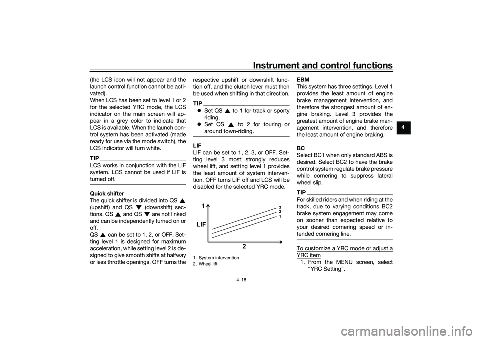
LIF can be set to 1, 2, 3, or OFF. Set-
ting level 3 most strongly reduces
wheel lift, and setting level 1 provides
the least amount of system interven-
tion. OFF turns LIF off and LCS will be
disabled for the selected YRC mode. EBM
This system has three settings. Level 1
provides the least amount of engine
brake management intervention, and
therefore the strongest amount of en-
gine braking. Level 3 provides the
greatest amount of engine brake man-
agement intervention, and therefore
the least amount of engine braking.
BC
Select BC1 when only standard ABS is
desired. Select BC2 to have the brake
control system regulate brake pressure
while cornering to suppress lateral
wheel slip.
TIPFor skilled riders and when riding at the
track, due to varying conditions BC2
brake system engagement may come
on sooner than expected relative to
your desired cornering speed or in-
tended cornering line.To customize a YRC mode or adjust aYRC item1. From the MENU screen, select
1. System intervention
2. Wheel lift
1 3
2
1
LIF
2
UB3LE1E0.book Page 18 Tuesday, August 10, 2021 2:28 PM
Page 43 of 136
Instrument and control functions
4-20
4
or for YZF-R1M select the “ ”
mark to fine tune the ERS mode
settings.
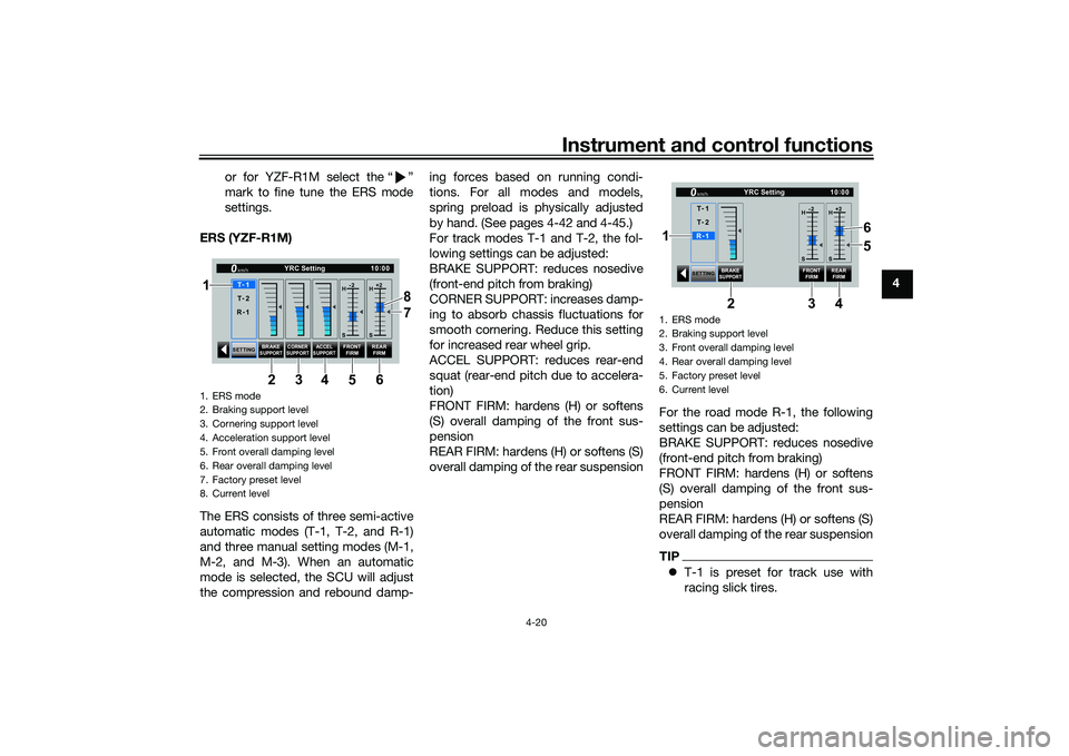
ERS (YZF-R1M)
The ERS consists of three semi-active
automatic modes (T-1, T-2, and R-1)
and three manual setting modes (M-1,
M-2, and M-3). When an automatic
mode is selected, the SCU will adjust
the compression and rebound damp- ing forces based on running condi-
tions. For all modes and models,
spring preload is physically adjusted
by hand. (See pages 4-42 and 4-45.)
For track modes T-1 and T-2, the fol-
lowing settings can be adjusted:
BRAKE SUPPORT: reduces nosedive
(front-end pitch from braking)
CORNER SUPPORT: increases damp-
ing to absorb chassis fluctuations for
smooth cornering. Reduce this setting
for increased rear wheel grip.
ACCEL SUPPORT: reduces rear-end
squat (rear-end pitch due to accelera-
tion)
FRONT FIRM: hardens (H) or softens
(S) overall damping of the front sus-
pension
REAR FIRM: hardens (H) or softens (S)
overall damping of the rear suspension
For the road mode R-1, the following
settings can be adjusted:
BRAKE SUPPORT: reduces nosedive
(front-end pitch from braking)
FRONT FIRM: hardens (H) or softens
(S) overall damping of the front sus-
pension
REAR FIRM: hardens (H) or softens (S)
overall damping of the rear suspension
TIP
T-1 is preset for track use with
racing slick tires.
1. ERS mode
2. Braking support level
3. Cornering support level
4. Acceleration support level
5. Front overall damping level
6. Rear overall damping level
7. Factory preset level
8. Current level
SETTING BRAKE
SUPPORT CORNER
SUPPORT
ACCELSUPPORT
FRONT FIRM REAR
FIRM
10 :
00
YRC Setting
km/hT -
1
H -2
S H
+2
S
T -
2
R -
1
1
34 8
5 7
6
2
1. ERS mode
2. Braking support level
3. Front overall damping level
4. Rear overall damping level
5. Factory preset level
6. Current level
SETTING
BRAKE
SUPPORT
FRONT
FIRM REAR
FIRM
10 :
00
YRC Setting
km/hR -
1
H -2
S H
+2
S
T -
1
T -
2
34
2
6
5
1
UB3LE1E0.book Page 20 Tuesday, August 10, 2021 2:28 PM
Page 56 of 136

Instrument and control functions
4-33
4
TIPTo prevent unintended shifts, the quick
shifter is programmed to ignore un-
clear input signals. Therefore, be sure
to shift using quick and sufficiently
forceful inputs.
EAU26827
Brake leverThe brake lever is located on the right
side of the handlebar. To apply the
front brake, pull the lever toward the
throttle grip.
The brake lever is equipped with a
brake lever position adjusting dial. To
adjust the distance between the brake
lever and the throttle grip, push the
brake lever away from the throttle grip
and rotate the adjusting dial. Make
sure the setting number on the adjust-
ing dial aligns with the match mark on
the brake lever.
EAU12944
Brake pedalThe brake pedal is located on the right
side of the motorcycle. To apply the
rear brake, press down on the brake
pedal.
1. Brake lever
2. Distance
3. Match mark
4. Adjusting dial
12
4
3
1. Brake pedal
UB3LE1E0.book Page 33 Tuesday, August 10, 2021 2:28 PM
Page 57 of 136
Instrument and control functions
4-34
4
EAU88462
Brake control system (BC)The brake control system regulates hy-
draulic brake pressure for the front and
rear wheels independently when the
respective brake lever or brake pedal is
applied and wheel lock is detected.
There are two settings, BC1 and BC2.
BC1 is standard ABS, which adjusts
brake pressure based on vehicle
speed and wheel speed data. BC1 is
designed to engage and maximize
braking when the vehicle is upright.
Regarding ABS, operate the brakes as
you would conventional brakes. When
the brake control system engages, a
pulsating sensation may be felt at the
brake lever or brake pedal as the hy-
draulic unit rapidly applies and reduces
brake pressure. In this situation, conti-
nue to apply the brake lever and brake
pedal to allow the ABS to work—do
not “pump the brakes” as this will re-
duce braking effectiveness.
WARNING
EWA16051
Always keep a sufficient distance
from the vehicle ahead to match the
riding speed even with ABS.
The ABS performs best with
long braking distances.
On certain surfaces, such as
rough or gravel roads, the brak-
ing distance may be longer with
the ABS than without.
BC2 incorporates standard ABS and in
addition regulates braking power when
cornering to suppress lateral wheel
slip.
WARNING
EWA20891
The brake control system is not a
substitute for the use of proper rid-
ing and braking techniques. The
brake control system cannot pre-
vent all loss of traction due to over-
braking from excessive speed, or
lateral wheel slip when braking on
slippery surfaces.The ABS hydraulic unit is monitored by
the ABS ECU, which will revert the sys-
tem to conventional braking if a mal-
function occurs.
TIPThe ABS performs a self-diagnosis test
when the vehicle is started and reach-
es a speed of 10 km/h (6 mi/h). During
this test, a clicking noise may be audi-
ble from the hydraulic control unit, and
a vibration may be felt at the brake le-
ver or pedal, but this is normal.NOTICE
ECA20100
Be careful not to damage the wheel
sensor or wheel sensor rotor; other-
wise, improper performance of the
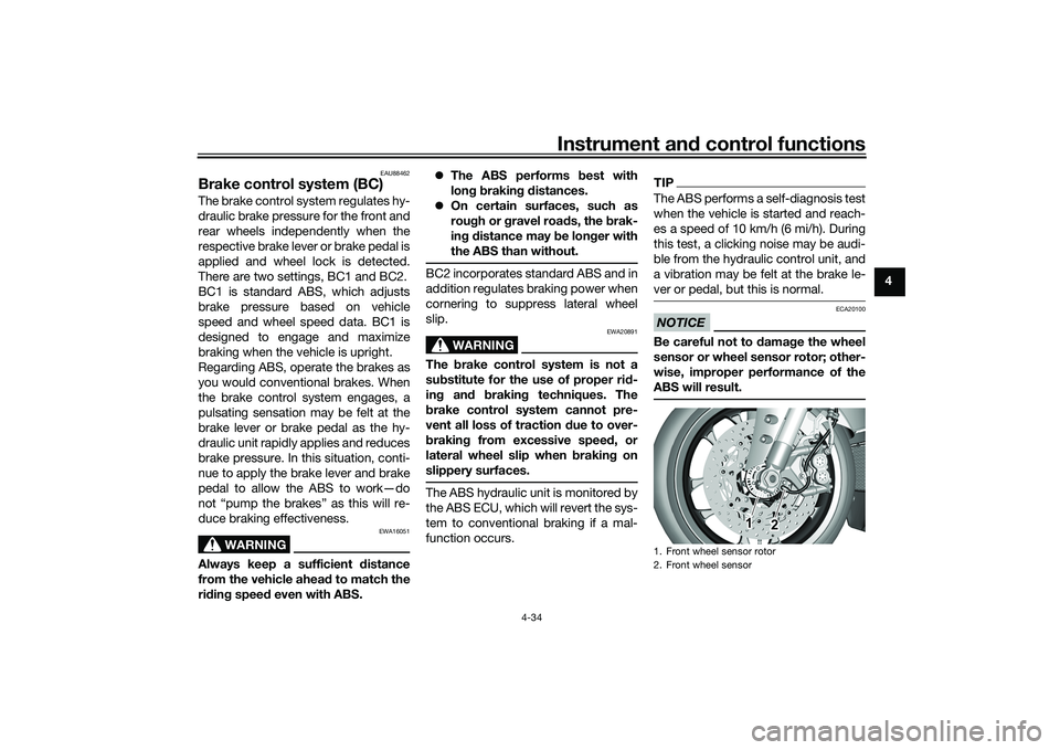
ABS will result.1. Front wheel sensor rotor
2. Front wheel sensor
1
2
UB3LE1E0.book Page 34 Tuesday, August 10, 2021 2:28 PM
Page 75 of 136
For your safety – pre-operation checks
5-1
5
EAU1559B
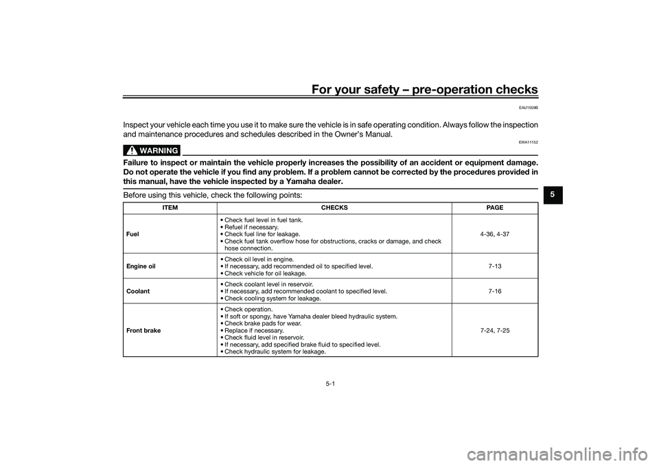
Inspect your vehicle each time you use it to make sure the vehicle is in safe operating condition. Always follow the inspection
and maintenance procedures and schedules described in the Owner’s Manual.
WARNING
EWA11152
Failure to inspect or maintain the vehicle properly increases the possibility of an accident or equipment damage.
Do not operate the vehicle if you find any problem. If a problem cannot be corrected by the procedures provided in
this manual, have the vehicle inspected by a Yamaha dealer.Before using this vehicle, check the following points:
ITEM CHECKS PAGE
Fuel • Check fuel level in fuel tank.
• Refuel if necessary.
• Check fuel line for leakage.
• Check fuel tank overflow hose for obstructions, cracks or damage, and check
hose connection. 4-36, 4-37
Engine oil • Check oil level in engine.
• If necessary, add recommended oil to specified level.
• Check vehicle for oil leakage. 7-13
Coolant • Check coolant level in reservoir.
• If necessary, add recommended coolant to specified level.
• Check cooling system for leakage. 7-16
Front brake • Check operation.
• If soft or spongy, have Yamaha dealer bleed hydraulic system.
• Check brake pads for wear.
• Replace if necessary.
• Check fluid level in reservoir.
• If necessary, add specified brake fluid to specified level.
• Check hydraulic system for leakage. 7-24, 7-25
UB3LE1E0.book Page 1 Tuesday, August 10, 2021 2:28 PM
Page 76 of 136
For your safety – pre-operation checks
5-2
5
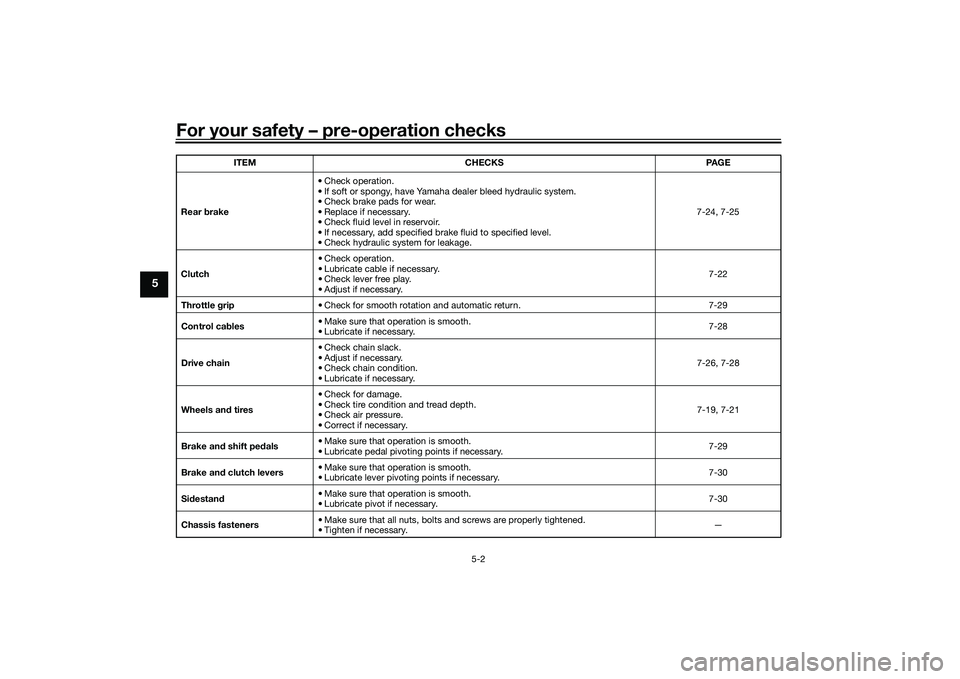
Rear brake• Check operation.
• If soft or spongy, have Yamaha dealer bleed hydraulic system.
• Check brake pads for wear.
• Replace if necessary.
• Check fluid level in reservoir.
• If necessary, add specified brake fluid to specified level.
• Check hydraulic system for leakage. 7-24, 7-25
Clutch • Check operation.
• Lubricate cable if necessary.
• Check lever free play.
• Adjust if necessary.
7-22
Throttle grip • Check for smooth rotation and automatic return. 7-29
Control cables • Make sure that operation is smooth.
• Lubricate if necessary. 7-28
Drive chain • Check chain slack.
• Adjust if necessary.
• Check chain condition.
• Lubricate if necessary.
7-26, 7-28
Wheels and tires •Check for damage.
• Check tire condition and tread depth.
• Check air pressure.
• Correct if necessary.
7-19, 7-21
Brake and shift pedals • Make sure that operation is smooth.
• Lubricate pedal pivoting points if necessary. 7-29
Brake and clutch levers • Make sure that operation is smooth.
• Lubricate lever pivoting points if necessary.
7-30
Sidestand • Make sure that operation is smooth.
• Lubricate pivot if necessary.
7-30
Chassis fasteners • Make sure that all nuts, bolts and screws are properly tightened.
• Tighten if necessary. —
ITEM CHECKS PAGE
UB3LE1E0.book Page 2 Tuesday, August 10, 2021 2:28 PM
Page 80 of 136
Operation and important riding points
6-3
6
EAU67084
ShiftingShifting gears lets you control the
amount of engine power available for
starting off, accelerating, climbing hills,
etc.
This model is equipped with a quick
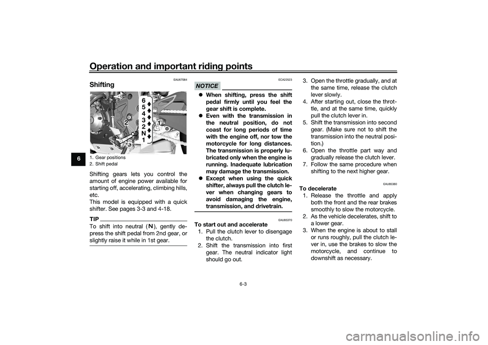
shifter. See pages 3-3 and 4-18.TIPTo shift into neutral ( ), gently de-
press the shift pedal from 2nd gear, or
slightly raise it while in 1st gear.
NOTICE
ECA22523
When shifting, press the shift
pedal firmly until you feel the
gear shift is complete.
Even with the transmission in
the neutral position, do not
coast for long periods of time
with the engine off, nor tow the
motorcycle for long distances.
The transmission is properly lu-
bricated only when the engine is
running. Inadequate lubrication
may damage the transmission.
Except when using the quick
shifter, always pull the clutch le-
ver when changing gears to
avoid damaging the engine,
transmission, and drivetrain.
EAU85370
To start out and accelerate
1. Pull the clutch lever to disengage the clutch.
2. Shift the transmission into first gear. The neutral indicator light
should go out. 3. Open the throttle gradually, and at
the same time, release the clutch
lever slowly.
4. After starting out, close the throt- tle, and at the same time, quickly
pull the clutch lever in.
5. Shift the transmission into second gear. (Make sure not to shift the
transmission into the neutral posi-
tion.)
6. Open the throttle part way and gradually release the clutch lever.
7. Follow the same procedure when shifting to the next higher gear.
EAU85380
To decelerate1. Release the throttle and apply both the front and the rear brakes
smoothly to slow the motorcycle.
2. As the vehicle decelerates, shift to a lower gear.
3. When the engine is about to stall or runs roughly, pull the clutch le-
ver in, use the brakes to slow the
motorcycle, and continue to
downshift as necessary.
1. Gear positions
2. Shift pedal
2
1 1
1
N 2 3
4
5
6
UB3LE1E0.book Page 3 Tuesday, August 10, 2021 2:28 PM
Page 81 of 136
Operation and important riding points
6-4
6
4. Once the motorcycle has
stopped, the transmission can be
shifted into the neutral position.
The neutral indicator light should
come on and then the clutch lever
can be released.
WARNING
EWA17380
Improper braking can cause
loss of control or traction. Al-
ways use both brakes and apply
them smoothly.
Make sure that the motorcycle
and the engine have sufficiently
slowed before shifting to a low-
er gear. Engaging a lower gear
when the vehicle or engine
speed is too high could make
the rear wheel lose traction or
the engine to over-rev. This
could cause loss of control, an
accident and injury. It could also
cause engine or drive train dam-
age.
EAU16811
Tips for reducing fuel con-
sumptionFuel consumption depends largely on
your riding style. Consider the follow-
ing tips to reduce fuel consumption:
Shift up swiftly, and avoid high en-
gine speeds during acceleration.
Do not rev the engine while shift-
ing down, and avoid high engine
speeds with no load on the en-
gine.
Turn the engine off instead of let-
ting it idle for an extended length
of time (e.g., in traffic jams, at traf-
fic lights or at railroad crossings).
EAU17214
ParkingWhen parking, stop the engine, and
then remove the key from the main
switch.
WARNING
EWA10312
Since the engine and exhaust
system can become very hot,
park in a place where pedestri-
ans or children are not likely to
touch them and be burned.
Do not park on a slope or on soft
ground, otherwise the vehicle
may overturn, increasing the
risk of a fuel leak and fire.
Do not park near grass or other
flammable materials which
might catch fire.
UB3LE1E0.book Page 4 Tuesday, August 10, 2021 2:28 PM