warning YAMAHA YZF-R1M 2022 Owner's Manual
[x] Cancel search | Manufacturer: YAMAHA, Model Year: 2022, Model line: YZF-R1M, Model: YAMAHA YZF-R1M 2022Pages: 136, PDF Size: 6.01 MB
Page 65 of 136

Instrument and control functions
4-42
4
EAU39672
Rear view mirrorsThe rear view mirrors of this vehicle
can be folded forward or backward for
parking in narrow spaces. Fold the mir-
rors back to their original position be-
fore riding.
WARNING
EWA14372
Be sure to fold the rear view mirrors
back to their original position before
riding.
EAU66478
Adjusting the front forkNOTICE
ECA22472
Use extra care to avoid scratch-
ing the anodized finish when
making suspension adjust-
ments.
To avoid damaging the suspen-
sion’s internal mechanisms, do
not attempt to turn beyond the
maximum or minimum settings.YZF-R1
This model is equipped with adjustable
suspension. The spring preload, re-
bound damping force, and compres-
sion damping force of each leg can be
adjusted.
WARNING
EWA10181
Always adjust both fork legs equally,
otherwise poor handling and loss of
stability may result.Spring preload
Turn the adjusting nut in direction (a) to
increase the spring preload. Turn the adjusting nut in direction (b) to
decrease the spring preload.
To set the spring preload, turn the ad-
juster in direction (b) until it stops, and
then count the turns in direction (a).
1. Riding position
2. Parking position11
22
1. Spring preload adjusting nut
Spring preload setting:
Minimum (soft): 0 turn(s) in direction (a)
Standard: 6 turn(s) in direction (a)
Maximum (hard):
15 turn(s) in direction (a)
(b)
(a) 1
UB3LE1E0.book Page 42 Tuesday, August 10, 2021 2:28 PM
Page 67 of 136

Instrument and control functions
4-44
4
TIPWhen turning the damping force
adjuster in direction (a), the 0 click
position and the 1 click position
may be the same.
When turning the damping force
adjuster in direction (b), it may
click beyond the stated specifica-
tions, however such adjustments
are ineffective and may damage
the suspension.YZF-R1M
This model is equipped with ÖHLINS
electronic racing suspension with gas
reservoir. The compression and re-
bound damping forces are electroni-
cally adjusted (see ERS on page 4-20).
The spring preload is manually adjust-
ed.
WARNING
EWA20900
The front fork legs contain highly
pressurized nitrogen gas. Read and
understand the following informa-
tion before handling the front fork
legs.
Do not subject the axle brackets
to open flame or other heat
source. This may cause the
units to explode due to exces-
sive gas pressure.
Do not attempt to open the gas
cylinder assemblies.
Do not deform or damage the
cylinders in any way. Cylinder
damage will result in poor
damping performance.
Do not dispose of a damaged or
worn-out front fork leg yourself.
Take the front fork leg to a
Yamaha dealer for disposal.Spring preload 1. Turn the vehicle off.
2. Slide the rubber cover back at each coupler. 3. Remove the coupler on each front
fork. NOTICE: To prevent dam-
aging the couplers, do not use
sharp tools or excessive force.
[ECA22770]
4. Turn the adjusting bolt in direction (a) to increase the spring preload.
Turn the adjusting bolt in direction
(b) to decrease the spring preload.
To set the spring preload, turn the
adjuster in direction (b) until it
stops, and then count the turns in
direction (a).
Compression damping setting:Minimum (soft):
23 click(s) in direction (b)
Standard:
17 click(s) in direction (b)
Maximum (hard): 1 click(s) in direction (b)
1. Rubber cover
2. Coupler
2
1
UB3LE1E0.book Page 44 Tuesday, August 10, 2021 2:28 PM
Page 68 of 136
Instrument and control functions
4-45
4
TIPWhen turning the spring preload ad-
juster in direction (a), it may turn be-
yond the stated specifications,
however such adjustments are ineffec-
tive and may damage the suspension.5. Attach the coupler on each fork.
6. Slide the rubber cover to the orig-inal position.
EAU66499
Adjusting the shock absorber
assembly
WARNING
EWA10222
This shock absorber assembly con-
tains highly pressurized nitrogen
gas. Read and understand the fol-
lowing information before handling
the shock absorber assembly.
Do not tamper with or attempt
to open the cylinder assembly.
Do not subject the shock ab-
sorber assembly to an open
flame or other high heat source.
This may cause the unit to ex-
plode due to excessive gas
pressure.
Do not deform or damage the
cylinder in any way. Cylinder
damage will result in poor
damping performance.
Do not dispose of a damaged or
worn-out shock absorber as-
sembly yourself. Take the shock
absorber assembly to a Yamaha
dealer for any service.
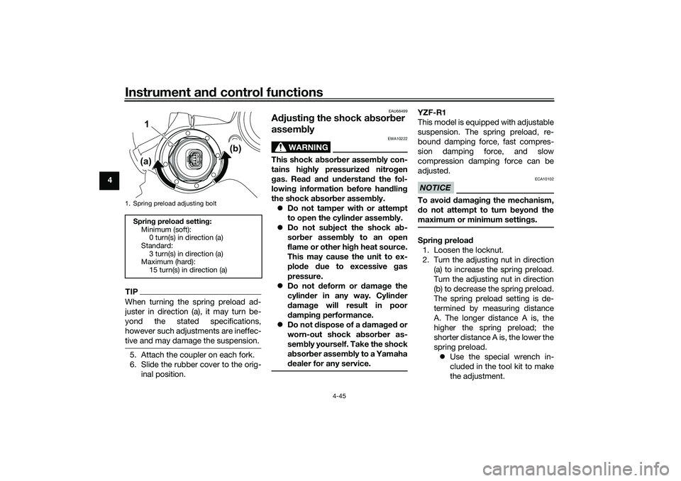
YZF-R1
This model is equipped with adjustable
suspension. The spring preload, re-
bound damping force, fast compres-
sion damping force, and slow
compression damping force can be
adjusted.NOTICE
ECA10102
To avoid damaging the mechanism,
do not attempt to turn beyond the
maximum or minimum settings.Spring preload
1. Loosen the locknut.
2. Turn the adjusting nut in direction (a) to increase the spring preload.
Turn the adjusting nut in direction
(b) to decrease the spring preload.
The spring preload setting is de-
termined by measuring distance
A. The longer distance A is, the
higher the spring preload; the
shorter distance A is, the lower the
spring preload. Use the special wrench in-
cluded in the tool kit to make
the adjustment.
1. Spring preload adjusting boltSpring preload setting:
Minimum (soft):0 turn(s) in direction (a)
Standard: 3 turn(s) in direction (a)
Maximum (hard):
15 turn(s) in direction (a)
1
(a) (b)
UB3LE1E0.book Page 45 Tuesday, August 10, 2021 2:28 PM
Page 72 of 136

Instrument and control functions
4-49
4
EAU67050
EXUP systemThis model is equipped with Yamaha’s
EXUP (EXhaust Ultimate Power valve)
system. This system boosts engine
power by means of a valve that con-
trols exhaust flow within the exhaust
chamber.NOTICE
ECA15611
The EXUP system has been set and
extensively tested at the Yamaha
factory. Changing these settings
without sufficient technical knowl-
edge may result in poor perfor-
mance of or damage to the engine.
EAU70641
Auxiliary DC connectorThis vehicle is equipped with an auxil-
iary DC connector. Consult your
Yamaha dealer before installing any accessories.
EAU15306
SidestandThe sidestand is located on the left
side of the frame. Raise the sidestand
or lower it with your foot while holding
the vehicle upright.TIPThe built-in sidestand switch is part of
the ignition circuit cut-off system,
which cuts the ignition in certain situa-
tions. (See the following section for an
explanation of the ignition circuit cut-
off system.)
WARNING
EWA10242
The vehicle must not be ridden with
the sidestand down, or if the side-
stand cannot be properly moved up (or does not stay up), otherwise the
sidestand could contact the ground
and distract the operator, resulting
in a possible loss of control.
Yamaha’s ignition circuit cut-off system has been designed to assist
the operator in fulfilling the respon-
sibility of raising the sidestand be-
fore starting off. Therefore, check
UB3LE1E0.book Page 49 Tuesday, August 10, 2021 2:28 PM
Page 74 of 136
Instrument and control functions
4-51
4
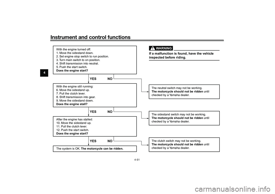
With the engine turned off:
1. Move the sidestand down.
2. Set engine stop switch to run position.
3. Turn main switch to on position.
4. Shift transmission into neutral.
5. Push the start switch.
Does the engine start?
With the engine still running:
6. Move the sidestand up.
7. Pull the clutch lever.
8. Shift transmission into gear.
9. Move the sidestand down.
Does the engine stall?
After the engine has stalled:
10. Move the sidestand up.
11. Pull the clutch lever.
12. Push the start switch.
Does the engine start?
The system is OK. The motorcycle can be ridden.
YES NO YES NO YES NO
The neutral switch may not be working.
The motorcycle should not be ridden until
checked by a Yamaha dealer.
The clutch switch may not be working.
The motorcycle should not be ridden until
checked by a Yamaha dealer.The sidestand switch may not be working.
The motorcycle should not be ridden until
checked by a Yamaha dealer.If a malfunction is found, have the vehicle
inspected before riding.
WARNING
UB3LE1E0.book Page 51 Tuesday, August 10, 2021 2:28 PM
Page 75 of 136
For your safety – pre-operation checks
5-1
5
EAU1559B
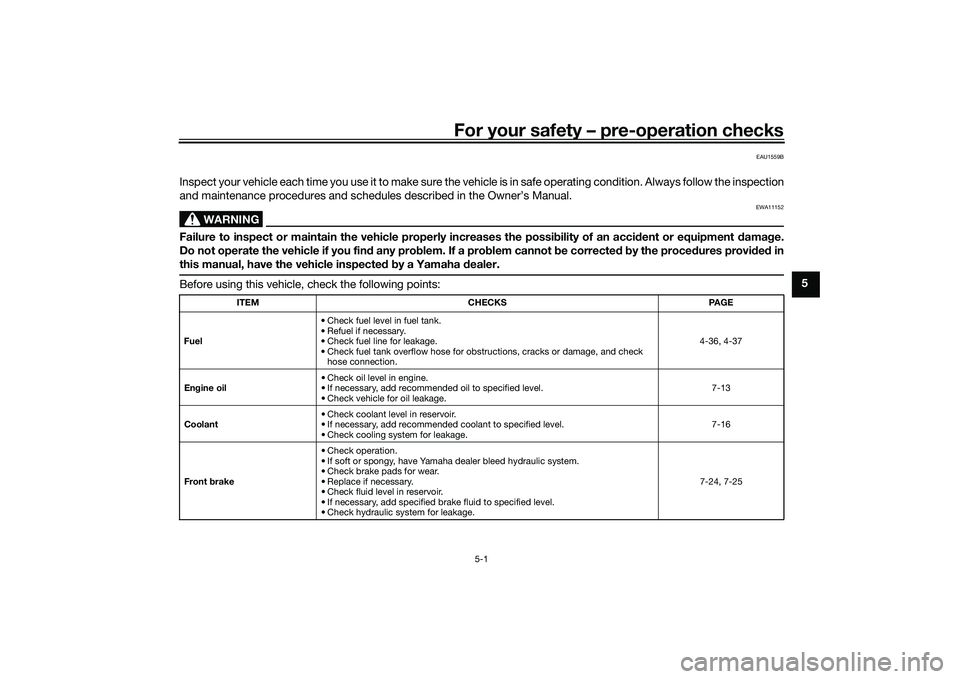
Inspect your vehicle each time you use it to make sure the vehicle is in safe operating condition. Always follow the inspection
and maintenance procedures and schedules described in the Owner’s Manual.
WARNING
EWA11152
Failure to inspect or maintain the vehicle properly increases the possibility of an accident or equipment damage.
Do not operate the vehicle if you find any problem. If a problem cannot be corrected by the procedures provided in
this manual, have the vehicle inspected by a Yamaha dealer.Before using this vehicle, check the following points:
ITEM CHECKS PAGE
Fuel • Check fuel level in fuel tank.
• Refuel if necessary.
• Check fuel line for leakage.
• Check fuel tank overflow hose for obstructions, cracks or damage, and check
hose connection. 4-36, 4-37
Engine oil • Check oil level in engine.
• If necessary, add recommended oil to specified level.
• Check vehicle for oil leakage. 7-13
Coolant • Check coolant level in reservoir.
• If necessary, add recommended coolant to specified level.
• Check cooling system for leakage. 7-16
Front brake • Check operation.
• If soft or spongy, have Yamaha dealer bleed hydraulic system.
• Check brake pads for wear.
• Replace if necessary.
• Check fluid level in reservoir.
• If necessary, add specified brake fluid to specified level.
• Check hydraulic system for leakage. 7-24, 7-25
UB3LE1E0.book Page 1 Tuesday, August 10, 2021 2:28 PM
Page 78 of 136
Operation and important riding points
6-1
6
EAU15952
Read the Owner’s Manual carefully to
become familiar with all controls. If
there is a control or function you do not
understand, ask your Yamaha dealer.
WARNING
EWA10272
Failure to familiarize yourself with
the controls can lead to loss of con-
trol, which could cause an accident
or injury.
EAU16842
Engine break-inThere is never a more important period
in the life of your engine than the period
between 0 and 1600 km (1000 mi). For
this reason, you should read the fol-
lowing material carefully.
Since the engine is brand new, do not
put an excessive load on it for the first
1600 km (1000 mi). The various parts in
the engine wear and polish themselves
to the correct operating clearances.
During this period, prolonged full-throt-
tle operation or any condition that
might result in engine overheating
must be avoided.
EAU17085
0–1000 km (0–600 mi)
Avoid prolonged operation above 7000
r/min. NOTICE: After 1000 km (600
mi) of operation, the engine oil must
be changed and the oil filter car-
tridge or element replaced.
[ECA10303]
1000–1600 km (600–1000 mi)
Avoid prolonged operation above 8400
r/min. 1600 km (1000 mi) and beyond
The vehicle can now be operated nor-
mally.
NOTICE
ECA10311
Keep the engine speed out of
the tachometer red zone.
If any engine trouble should oc-
cur during the engine break-in
period, immediately have a
Yamaha dealer check the vehi-
cle.TIPDuring and after the engine break-in
period, the exhaust heat may cause
discoloration of the exhaust pipe, but
this is normal.
UB3LE1E0.book Page 1 Tuesday, August 10, 2021 2:28 PM
Page 79 of 136
Operation and important riding points
6-2
6
EAU88420
Starting the engineThe ignition circuit cut-off system will
enable starting when: the transmission is in the neutral
position or
the transmission is in gear, the
sidestand is up, and the clutch le-
ver is pulled.
To start the engine1. Turn the main switch on and set the engine stop switch to the run
position.
2. Confirm the indicator and warning light(s) come on for a few sec-
onds, and then go off. (See page
4-6.)TIPDo not start the engine if the mal-
function indicator light remains on.
The oil pressure and coolant tem-
perature warning light should
come on and stay on until the en-
gine is started.
The ABS warning light should
come on and stay on until the ve-
hicle reaches a speed of 10 km/h
(6 mi/h).
NOTICE
ECA24110
If a warning or indicator light does
not work as described above, have a
Yamaha dealer check the vehicle.3. Shift the transmission into the
neutral position.
4. Start the engine by pushing the start switch.
5. Release the start switch when the engine starts, or after 5 seconds.
Wait 10 seconds before pressing
the switch again to allow battery
voltage to restore.NOTICE
ECA11043
For maximum engine life, never ac-
celerate hard when the engine is
cold!
EAU68221
TIPThis model is equipped with: an inertial measurement unit
(IMU). This unit stops the engine in
case of a turnover. Turn the main
switch off and then on before at-
tempting to restart the engine.
Failing to do so will prevent the en-
gine from starting even though the
engine will crank when pushing
the start switch.
an engine auto-stop system. The
engine stops automatically if left
idling for 20 minutes. If the engine
stops, simply push the start
switch to restart the engine.
UB3LE1E0.book Page 2 Tuesday, August 10, 2021 2:28 PM
Page 81 of 136
Operation and important riding points
6-4
6
4. Once the motorcycle has
stopped, the transmission can be
shifted into the neutral position.
The neutral indicator light should
come on and then the clutch lever
can be released.
WARNING
EWA17380
Improper braking can cause
loss of control or traction. Al-
ways use both brakes and apply
them smoothly.
Make sure that the motorcycle
and the engine have sufficiently
slowed before shifting to a low-
er gear. Engaging a lower gear
when the vehicle or engine
speed is too high could make
the rear wheel lose traction or
the engine to over-rev. This
could cause loss of control, an
accident and injury. It could also
cause engine or drive train dam-
age.
EAU16811
Tips for reducing fuel con-
sumptionFuel consumption depends largely on
your riding style. Consider the follow-
ing tips to reduce fuel consumption:
Shift up swiftly, and avoid high en-
gine speeds during acceleration.
Do not rev the engine while shift-
ing down, and avoid high engine
speeds with no load on the en-
gine.
Turn the engine off instead of let-
ting it idle for an extended length
of time (e.g., in traffic jams, at traf-
fic lights or at railroad crossings).
EAU17214
ParkingWhen parking, stop the engine, and
then remove the key from the main
switch.
WARNING
EWA10312
Since the engine and exhaust
system can become very hot,
park in a place where pedestri-
ans or children are not likely to
touch them and be burned.
Do not park on a slope or on soft
ground, otherwise the vehicle
may overturn, increasing the
risk of a fuel leak and fire.
Do not park near grass or other
flammable materials which
might catch fire.
UB3LE1E0.book Page 4 Tuesday, August 10, 2021 2:28 PM
Page 82 of 136

Periodic maintenance and adjustment
7-1
7
EAU17246
Periodic inspection, adjustment, and
lubrication will keep your vehicle in the
safest and most efficient condition
possible. Safety is an obligation of the
vehicle owner/operator. The most im-
portant points of vehicle inspection,
adjustment, and lubrication are ex-
plained on the following pages.
The intervals given in the periodic
maintenance charts should be simply
considered as a general guide under
normal riding conditions. However, de-
pending on the weather, terrain, geo-
graphical location, and individual use,
the maintenance intervals may need to
be shortened.
WARNING
EWA10322
Failure to properly maintain the vehi-
cle or performing maintenance ac-
tivities incorrectly may increase
your risk of injury or death during
service or while using the vehicle. If
you are not familiar with vehicle ser-
vice, have a Yamaha dealer perform
service.
WARNING
EWA15123
Turn off the engine when performing
maintenance unless otherwise
specified. A running engine has moving
parts that can catch on body
parts or clothing and electrical
parts that can cause shocks or
fires.
Running the engine while ser-
vicing can lead to eye injury,
burns, fire, or carbon monoxide
poisoning – possibly leading to
death. See page 1-3 for more in-
formation about carbon monox-
ide.
WARNING
EWA15461
Brake discs, calipers, drums, and
linings can become very hot during
use. To avoid possible burns, let
brake components cool before
touching them.
EAU17303
Emission controls not only function to
ensure cleaner air, but are also vital to
proper engine operation and maximum
performance. In the following periodic
maintenance charts, the services relat-
ed to emissions control are grouped
separately. These services require
specialized data, knowledge, and
equipment. Maintenance, replace-
ment, or repair of the emission control
devices and systems may be per-
formed by any repair establishment or
individual that is certified (if applicable).
Yamaha dealers are trained and equipped to perform these particular
services.
UB3LE1E0.book Page 1 Tuesday, August 10, 2021 2:28 PM