engine YAMAHA YZF-R7 1999 Owners Manual
[x] Cancel search | Manufacturer: YAMAHA, Model Year: 1999, Model line: YZF-R7, Model: YAMAHA YZF-R7 1999Pages: 381, PDF Size: 18.88 MB
Page 5 of 381
EC080000
HOW TO USE
THIS MANUAL
EC081000
PARTICULARLY IMPORTANT
INFORMATION
The Safety Alert Symbol means ATTEN-
TION! BECOME ALERT! YOUR SAFETY IS
INVOLVED!
Failure to follow WARNING instructions
could result in severe injury or death to the
machine operator, a bystander, or a person
inspecting or repairing the motorcycle.
A CAUTION indicates special precautions
that must be taken to avoid damage to the
motorcycle.
NOTE:
A NOTE provides key information to make
procedures easier or clearer.
WARNING
CAUTION:
EC082000
FINDING THE REQUIRED PAGE
1. This manual consists of eight chapters;
“General Information”, “Specifica-
tions”, “Periodic checks and adjust-
ments”, “Engine”, “Cooling system”,
“Electronic fuel injection”, “Chassis”,
“Electrical”.
2. The table of contents is at the begin-
ning of the manual. Look over the gen-
eral layout of the book before finding
the required chapter and item.
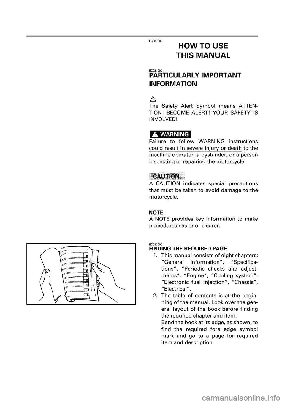
Bend the book at its edge, as shown, to
find the required fore edge symbol
mark and go to a page for required
item and description.
Page 7 of 381
EB004000
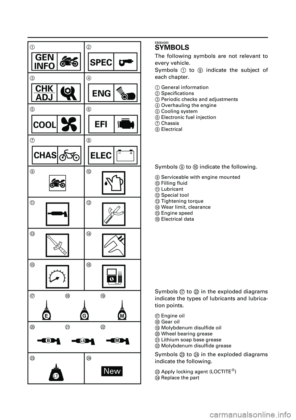
SYMBOLS
The following symbols are not relevant to
every vehicle.
Symbols
1
to
9
indicate the subject of
each chapter.
1
General information
2
Specifications
3
Periodic checks and adjustments
4
Overhauling the engine
5
Cooling system
6
Electronic fuel injection
7
Chassis
8
Electrical
Symbols
9
to
F
indicate the following.
9
Serviceable with engine mounted
0
Filling fluid
A
Lubricant
B
Special tool
C
Tightening torque
D
Wear limit, clearance
E
Engine speed
F
Electrical data
Symbols
G
to
L
in the exploded diagrams
indicate the types of lubricants and lubrica-
tion points.
G
Engine oil
H
Gear oil
I
Molybdenum disulfide oil
J
Wheel bearing grease
K
Lithium soap base grease
L
Molybdenum disulfide grease
Symbols
M
to
N
in the exploded diagrams
indicate the following.
MApply locking agent (LOCTITE
â)
NReplace the part 12
34
56
78
90
AB
CD
E F
GHI
JKL
M N
SPEC
CHK
ADJENG
COOLEFI
CHAS–+ELEC
T R..
GME
BLSM
LTNew
Page 9 of 381
INDEX
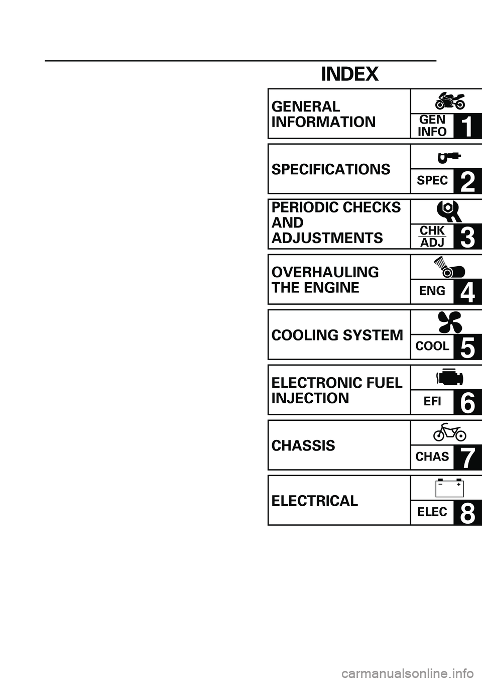
GENERAL
INFORMATION
1
SPECIFICATIONS
SPEC
2
PERIODIC CHECKS
AND
ADJUSTMENTS
3
OVERHAULING
THE ENGINE
ENG
4
COOLING SYSTEM
COOL
5
ELECTRONIC FUEL
INJECTION
EFI
6
CHASSIS
CHAS
7
ELECTRICAL
ELEC
8
GEN
INFO
CHK
ADJ
–+
Page 10 of 381
EC0A0000
CONTENTS
CHAPTER 1
GENERAL INFORMATION
GIVE SAFETY THE RIGHT OF WAY ........ 1-1
DESCRIPTION ........................................... 1-2
INSTRUMENT AND CONTROL
FUNCTIONS .............................................. 1-4
OPERATION AND IMPORTANT
RIDING POINTS ...................................... 1-12
INCLUDED ACCESSORIES ..................... 1-14
MOTORCYCLE CARE AND
STORAGE ................................................ 1-15
CONSUMER INFORMATION ................. 1-17
TROUBLESHOOTING .............................. 1-18
IMPORTANT INFORMATION ................. 1-20
CHECKING THE CONNECTIONS ........... 1-22
SPECIAL TOOLS ..................................... 1-23
CHAPTER 2
SPECIFICATIONS
GENERAL SPECIFICATIONS .................... 2-1
ENGINE SPECIFICATIONS ....................... 2-2
CHASSIS SPECIFICATIONS ................... 2-11
ELECTRICAL SPECIFICATIONS ............. 2-15
TIGHTENING TORQUES ........................ 2-17
LUBRICATION POINTS AND
LUBRICANT TYPES ................................ 2-22
OIL FLOW CHART ................................... 2-24
COOLANT FLOW CHART ....................... 2-25
CABLE ROUTING .................................... 2-26
Page 11 of 381

CHAPTER 3
PERIODIC CHECKS AND
ADJUSTMENTS
INTRODUCTION ....................................... 3-1
PERIODIC MAINTENANCE AND
LUBRICATION INTERVALS ...................... 3-1
GENERAL MAINTENANCE AND
LUBRICATION CHART .............................. 3-2
FUEL TANK AND AIR FILTER .................. 3-4
COWLINGS ............................................... 3-6
ENGINE ..................................................... 3-9
CHASSIS ................................................. 3-36
ELECTRICAL SYSTEM ............................ 3-55
CHAPTER 4
OVERHAULING THE ENGINE
ENGINE ..................................................... 4-1
CAMSHAFTS ............................................. 4-8
CYLINDER HEAD .................................... 4-18
VALVES AND VALVE SPRINGS ............ 4-21
GENERATOR ........................................... 4-32
PICKUP COIL ........................................... 4-35
CLUTCH ................................................... 4-39
SHIFT SHAFT .......................................... 4-48
OIL PAN AND OIL PUMP ....................... 4-50
CRANKCASE ........................................... 4-56
CONNECTING RODS AND
PISTONS ................................................. 4-63
CRANKSHAFT ......................................... 4-74
TRANSMISSION ..................................... 4-79
CHAPTER 5
COOLING SYSTEM
RADIATOR AND THERMOSTAT .............. 5-1
RADIATOR AND THERMOSTAT .............. 5-3
OIL COOLER .............................................. 5-9
WATER PUMP ......................................... 5-12
Page 14 of 381

1 - 2
DESCRIPTION
DESCRIPTION
Left view
Right view
1. Front fork compression damping force adjusting screw
2. Front fork rebound damping force adjusting screw
3. Front fork spring preload adjusting bolt
4. Air filter
5. Starter (choke) “ “
6. Shift pedal
7. Rear shock absorber spring preload adjusting ring
8. Rear shock absorber compression damping force adjusting screw
9. Rear shock absorber rebound damping force adjusting screw
10. Fuses
11. Rear brake resorvoir
12. Rear brake pedal
13. Radiator cap and coolant reservoir tank cap
14. Engine oil filter
14
56
78
9
2,3
10
11
1213 14
1
Page 16 of 381
1 - 4
INSTRUMENT AND CONTROL FUNCTIONS
INSTRUMENT AND CONTROL FUNCTIONS
EAU00029
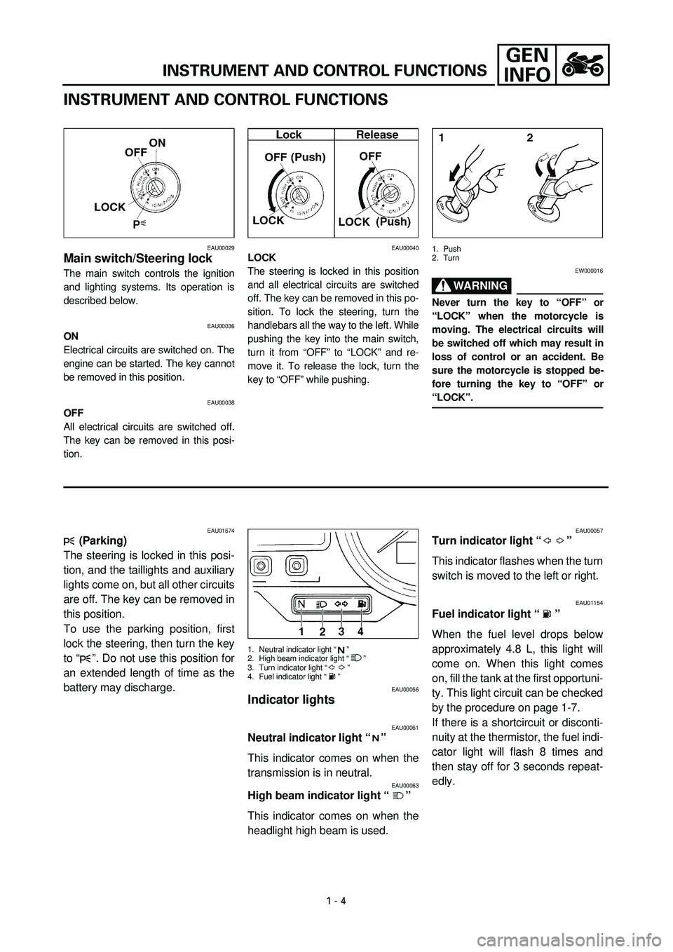
Main switch/Steering lock
The main switch controls the ignition
and lighting systems. Its operation is
described below.
EAU00036
ON
Electrical circuits are switched on. The
engine can be started. The key cannot
be removed in this position.
EAU00038
OFF
All electrical circuits are switched off.
The key can be removed in this posi-
tion.
EAU00040
LOCK
The steering is locked in this position
and all electrical circuits are switched
off. The key can be removed in this po-
sition. To lock the steering, turn the
handlebars all the way to the left. While
pushing the key into the main switch,
turn it from “OFF” to “LOCK” and re-
move it. To release the lock, turn the
key to “OFF” while pushing.
1. Push
2. Turn
EW000016
WARNING
Never turn the key to “OFF” or
“LOCK” when the motorcycle is
moving. The electrical circuits will
be switched off which may result in
loss of control or an accident. Be
sure the motorcycle is stopped be-
fore turning the key to “OFF” or
“LOCK”.
EAU01574
(Parking)
The steering is locked in this posi-
tion, and the taillights and auxiliary
lights come on, but all other circuits
are off. The key can be removed in
this position.
To use the parking position, first
lock the steering, then turn the key
to “ ”. Do not use this position for
an extended length of time as the
battery may discharge.
1.
Neutral indicator light “ ”
2. High beam indicator light “ ”
3. Turn indicator light “ ”
4. Fuel indicator light “ ”
EAU00056
Indicator lights
EAU00061
Neutral indicator light “ ”
This indicator comes on when the
transmission is in neutral.
EAU00063
High beam indicator light “ ”
This indicator comes on when the
headlight high beam is used.
EAU00057
Turn indicator light “ ”
This indicator flashes when the turn
switch is moved to the left or right.
EAU01154
Fuel indicator light “ ”
When the fuel level drops below
approximately 4.8 L, this light will
come on. When this light comes
on, fill the tank at the first opportuni-
ty. This light circuit can be checked
by the procedure on page 1-7.
If there is a shortcircuit or disconti-
nuity at the thermistor, the fuel indi-
cator light will flash 8 times and
then stay off for 3 seconds repeat-
edly.
Page 17 of 381

1 - 5
INSTRUMENT AND CONTROL FUNCTIONS
4 681012
14
x1000r/min
0
1 12
3 3
4
1. Warning light
2. Oil level symbol “ ”
3. Coolant temperature symbol “ ”
4. Engine trouble symbol “ ”
EAU01564
Warning light
This indicator light has three functions.
l
The light will come on and symbol
“ ” will flash if the engine oil
level is low.
If this symbol flashes, stop the en-
gine immediately and fill it with oil
to the specified level.
l
The light will come on and symbol
“ ” will flash if trouble occurs in
a monitoring circuit. In such a
case, take the motorcycle to a
Yamaha dealer to have the self-
diagnostic systems checked.
l
The light will come on and symbol
“ ” will flash if the coolant tem-
perature is too high. The following
chart shows the conditions of the
indicator light, symbol and tem-
perature display in accordance to
coolant temperature.
The light circuit can be checked by the
procedure on page 1-6.
EC000118
CAUTION:
l
Do not run the motorcycle until
you know it has sufficient en-
gine oil.
l
Do not run the motorcycle if the
engine is overheated.
NOTE:
Even if the oil is filled to the specified
level, the indicator light may flicker
when riding on a slope or during sud-
den acceleration or deceleration, but
this is normal.
CB-74ECB-74E
Coolant
temperatureDisplay Conditions What to do
~ 39 ˚CSymbol is on and “LO” is
displayed.OK. Go ahead with riding.
40 ˚C ~ 120 ˚CSymbol is on and temper-
ature is displayed.OK. Go ahead with riding.
121 ˚C ~ 139 ˚CSymbol and temperature
flash.
Warning light comes on.Stop the motorcycle and al-
low it to idle until coolant tem-
perature goes down.
If the temperature does not
go down, stop the engine.
140 ˚C ~ Symbol and message
“HI” flash.
Warning light comes on.Stop the engine and allow it
to cool. Seen page 1-19 if the
engine overheats.
—Symbol and message
“Err” flash.
Warning light comes on.Ask a Yamaha dealer to in-
spect the motorcycle.
C
C
C
C
C
Page 18 of 381

1 - 6
INSTRUMENT AND CONTROL FUNCTIONS
Warning light circuit check
CB-75ECB-75E
Warning light comes on. After a few seconds:Warning light does not come on.
Have a Yamaha
dealer inspect the
electrical circuit.
Turn the main switch to “ON”.
Have a Yamaha dealer inspect
the electrical circuit.
If symbol “ ” is on, check the
engine temperature. (See page 1-5.)
Warning light goes off.
No symbol is on.Symbol “ ”,
“ ” “ ” is on.
OK. Go ahead
with riding.
Warning light does not go off.
If symbol “ ”
is on, inspect the
oil level.
Oil level is OK.Oil level is low.
Have a Yamaha dealer
inspect the electrical
circuit.Supply
recommended
engine oil.
If the engine is hot,
allow it to cool and see
“Engine overheating”
in the troubleshooting
chart on page 1-19 for
instructions.If the engine
temperature is
normal, have a
Yamaha dealer
inspect the
electrical circuit.
If symbol “ ” is on.
Have a Yamaha dealer
inspect the self-
diagnostic systems.
Page 20 of 381

1 - 8
INSTRUMENT AND CONTROL FUNCTIONS
1. Clock, odometer
2. “SELECT” button
3. “RESET” button
Clock mode
To change the display to the clock
mode, push both the “SELECT” and
“RESET” buttons.
To change the display back to the
odometer mode, push the “RESET”
button.
To set the clock
1. Push both the “SELECT” and
“RESET” buttons for at least two
seconds.2. When the hour digits start flash-
ing, push the “RESET” button to
set the hours.
3. Push the “SELECT” button to
change the minutes.
4. When the minute digits start flash-
ing, push the “RESET” button to
set the minutes.
5. Push the “SELECT” button to start
the clock.
NOTE:
After setting the clock, be sure to push
the “SELECT” button before turning the
main switch to “OFF”, otherwise the
clock will not be set.
4 681012
14
x1000r/min
0
1 1
1. Tachometer
EAU00101
Tachometer
This model is equipped with an electric
tachometer so the rider can monitor the
engine speed and keep it within the
ideal power range.
EC000003
CAUTION:
Do not operate at 13,800 r/min and
above.
Diagnosis device
This model is equipped with a self diag-
nosis.
Refer to “ELECTRICAL CONTROL
SYSTEM USER MODE” in chapter 8.
If some trouble should occur in an elec-
trical circuit the tachometer will repeat-
edly display change in r/min.If this occurs take your motorcycle to a
Yamaha dealer for repair.
EC000004
CAUTION:
To prevent engine damage, be sure
to consult a Yamaha dealer as soon
as possible if the tachometer dis-
plays a repeated change in rpm.