tow bar YAMAHA YZF-R7 1999 Owners Manual
[x] Cancel search | Manufacturer: YAMAHA, Model Year: 1999, Model line: YZF-R7, Model: YAMAHA YZF-R7 1999Pages: 381, PDF Size: 18.88 MB
Page 21 of 381

1 - 9
INSTRUMENT AND CONTROL FUNCTIONS
1 1
2 2
4 4
5 53 3
1. Pass switch “PASS”
2. Lights switch
3. Dimmer switch
4. Turn signal switch
5. Horn switch “ ”
EAU00118
Handlebar switches
EAU00120
Pass switch “PASS”
Press the switch to operate the passing
light.
EAU00134
Lights switch
Turning the lights switch to “ ”,
turns on the auxiliary light, meter lights
and taillight. Turning the lights switch to
“ ”, turns the headlight on also.
EAU00121
Dimmer switch
Turn the switch to “ ” for the high
beam and to “ ” for the low beam.
EAU00127
Turn signal switch
To signal a right-hand turn, push the
switch to “ ”. To signal a left-hand
turn, push the switch to “ ”. Once
the switch is released it will return to the
center position. To cancel the signal,
push the switch in after it has returned
to the center position.
EAU00129
Horn switch “ ”
Press the switch to sound the horn.
1 1
2 2
1. Engine stop switch
2. Start switch “ ”
EAU00138
Engine stop switch
The engine stop switch is a safety de-
vice for use in an emergency such as
when the motorcycle overturns or if
trouble occurs in the throttle system.
Turn the switch to “ ” to start the en-
gine. In case of emergency, turn the
switch to “ ” to stop the engine.
EAU00143
Start switch “ ”
The starter motor cranks the engine
when pushing the start switch.
EC000005
CAUTION:
See starting instructions prior to
starting the engine.
a a1 1
2
2
1. Lever position adjusting dial
2. Arrow mark
a. Lever distance
EAU00153
Clutch lever
The clutch lever is located on the left
handlebar. It is equipped with a clutch
lever adjusting dial and a clutch switch,
which is integrated into the ignition cir-
cuit cut-off system. (Refer to the engine
starting procedures for a description of
this system.) To disengage the clutch,
pull the clutch lever toward the handle-
bar. To engage the clutch, release the
lever. The lever should be pulled rapid-
ly and released slowly for smooth
clutch operation. To adjust the distance between the
clutch lever and the handlebar grip,
turn the clutch adjusting dial while
pushing the lever forward. Make sure
the setting on the clutch lever adjusting
dial is aligned with the arrow mark.
Page 22 of 381

1 - 10
INSTRUMENT AND CONTROL FUNCTIONS
1 1
1. Shift pedal
EAU00157
Shift pedal
This motorcycle is equipped with a con-
stant-mesh 6-speed transmission.
The shift pedal is located on the left
side of the engine and is used in com-
bination with the clutch when shifting.
1. Lever position adjusting dial
2. Arrow mark
a. Lever distance
EAU00161
Front brake lever
The front brake lever is located on the
right handlebar and is equipped with a
brake lever adjusting dial.
To activate the front brake, pull the le-
ver toward the handlebar.
To adjust the front brake lever position,
turn the brake lever adjusting dial while
pulling the lever forward. Make sure the
setting on the brake lever adjusting dial
is aligned with the arrow mark.
1 1
1. Rear brake pedalEAU00162
Rear brake pedal
The rear brake pedal is on the right
side of the motorcycle. Press down on
the brake pedal to apply the rear brake.
1. OpenEAU00172
Fuel tank cap
To open
Insert the key and turn it 1/4 turn clock-
wise. The lock will be released and the
cap can be opened.
To close
Push the tank cap into position with the
key inserted. To remove the key, turn it
counterclockwise to the original posi-
tion.
1 1NOTE:
This tank cap cannot be closed unless
the key is in the lock. The key cannot
be removed if the cap is not locked
properly.
EW000023
WARNING
Be sure the cap is properly installed
and locked in place before riding the
motorcycle.
1. Filler tube
2. Fuel level
EAU01183
Fuel
Make sure there is sufficient fuel in the
tank. Fill the fuel tank to the bottom of
the filler tube as shown in the illustra-
tion.
EW000130
WARNING
Do not overfill the fuel tank. Avoid
spilling fuel on the hot engine. Do
not fill the fuel tank above the bot-
tom of the filler tube or it may over-
flow when the fuel heats up later and
expands.
Page 219 of 381

4 - 87
ENGTRANSMISSION
4. Check:
• transmission gear engagement
(each pinion gear to its respective
wheel gear)
Incorrect ® Reassemble the transmis-
sion axle assemblies.
5. Check:
• transmission gear movement
Rough movement ® Replace the
defective part(-s).
6. Check:
• circlips
Bends/damage/looseness ® Replace.
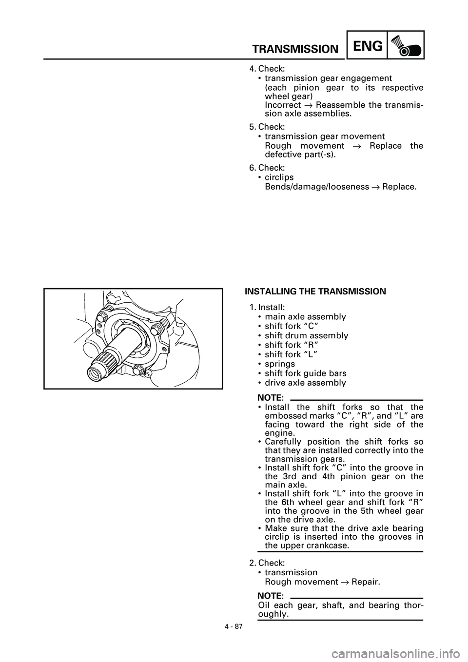
INSTALLING THE TRANSMISSION
1. Install:
• main axle assembly
• shift fork “C”
• shift drum assembly
• shift fork “R”
• shift fork “L”
• springs
• shift fork guide bars
• drive axle assembly
NOTE:
• Install the shift forks so that the
embossed marks “C”, “R”, and “L” are
facing toward the right side of the
engine.
• Carefully position the shift forks so
that they are installed correctly into the
transmission gears.
• Install shift fork “C” into the groove in
the 3rd and 4th pinion gear on the
main axle.
• Install shift fork “L” into the groove in
the 6th wheel gear and shift fork “R”
into the groove in the 5th wheel gear
on the drive axle.
• Make sure that the drive axle bearing
circlip is inserted into the grooves in
the upper crankcase.
2. Check:
• transmission
Rough movement ® Repair.
NOTE:
Oil each gear, shaft, and bearing thor-
oughly.