clock Abarth 500 2008 Owner handbook (in English)
[x] Cancel search | Manufacturer: ABARTH, Model Year: 2008, Model line: 500, Model: Abarth 500 2008Pages: 170, PDF Size: 3.04 MB
Page 14 of 170
13
SAFETY
DEVICES
CORRECT USE
OF THE
CAR
WARNING
LIGHTS AND
MESSAGES
IN AN
EMERGENCY
CAR
MAINTENANCE
TECHNICAL
SPECIFICATIONS
INDEX
YOUR CAR
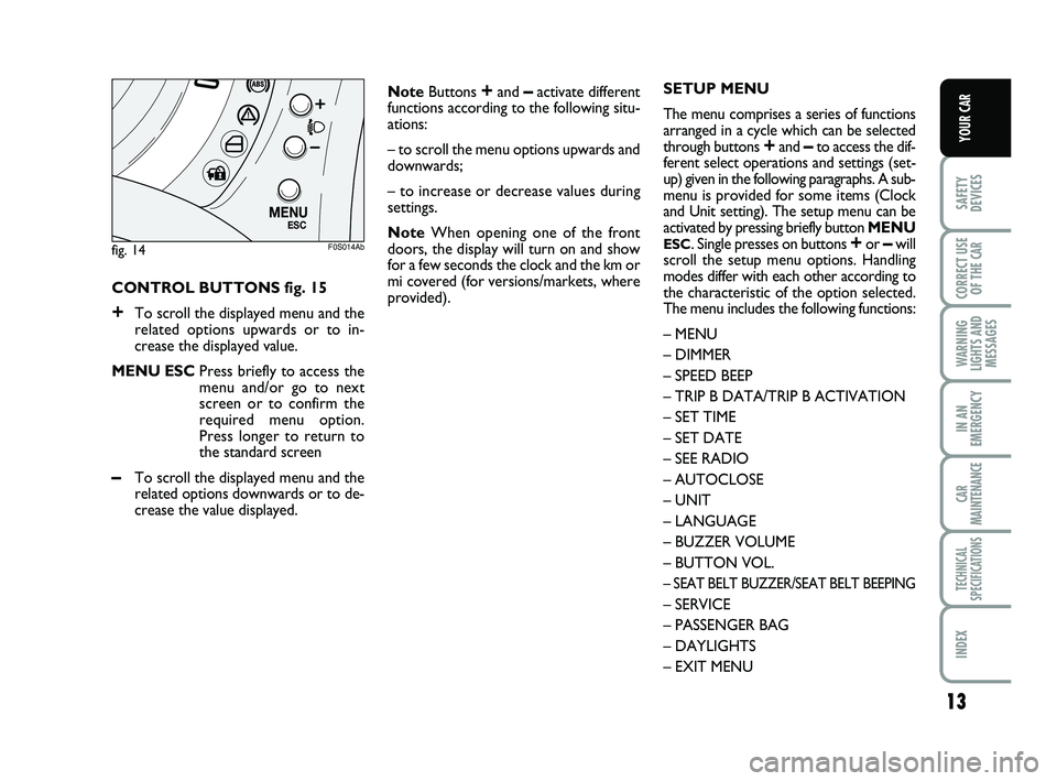
CONTROL BUTTONS fig. 15
+To scroll the displayed menu and the
related options upwards or to in-
crease the displayed value.
MENU ESCPress briefly to access the
menu and/or go to next
screen or to confirm the
required menu option.
Press longer to return to
the standard screen
–To scroll the displayed menu and the
related options downwards or to de-
crease the value displayed.NoteButtons
+and –activate different
functions according to the following situ-
ations:
– to scroll the menu options upwards and
downwards;
– to increase or decrease values during
settings.
NoteWhen opening one of the front
doors, the display will turn on and show
for a few seconds the clock and the km or
mi covered (for versions/markets, where
provided).
fig. 14
M E N UE S C
F0S014Ab
SETUP MENU
The menu comprises a series of functions
arranged in a cycle which can be selected
through buttons
+and –to access the dif-
ferent select operations and settings (set-
up) given in the following paragraphs. A sub-
menu is provided for some items (Clock
and Unit setting). The setup menu can be
activated by pressing briefly button MENU
ESC. Single presses on buttons +or –will
scroll the setup menu options. Handling
modes differ with each other according to
the characteristic of the option selected.
The menu includes the following functions:
– MENU
– DIMMER
– SPEED BEEP
– TRIP B DATA/TRIP B ACTIVATION
– SET TIME
– SET DATE
– SEE RADIO
– AUTOCLOSE
– UNIT
– LANGUAGE
– BUZZER VOLUME
– BUTTON VOL.
– SEAT BELT BUZZER/SEAT BELT BEEPING
– SERVICE
– PASSENGER BAG
– DAYLIGHTS
– EXIT MENU
001-022 ABARTH 500 GB 29-04-2009 9:40 Pagina 13
Page 17 of 170
16
SAFETY
DEVICES
CORRECT USE
OF THE
CAR
WARNING
LIGHTS AND
MESSAGES
IN AN
EMERGENCY
CAR
MAINTENANCE
TECHNICAL
SPECIFICATIONS
INDEX
YOUR CAR
Trip B data (Trip B on)
Through this option it is possible to acti-
vate (On) or deactivate (Off) the Trip B
(partial trip) display.
For further information see “Trip com-
puter”.
For activation / deactivation, proceed as
follows:
– briefly press button MENU
ESC: (On)
or (Off) will flash on the display (accord-
ing to previous setting);
– press button
+or –for setting;
– briefly press button MENU
ESCto go
back to the menu screen or press the but-
ton for long to go back to the standard
screen without storing settings.Set time (Clock)
This function enables to set the clock
through two sub-menus: “Time” and
“Mode”.
Proceed as follows:
– briefly press button MENU
ESC, the
display will show the two sub-menus
“Time” and “Mode”;
– press button
+or –to navigate the two
sub-menus;
– select the required option and then
press button MENU
ESC;
– when accessing the “Time” submenu:
briefly press button MENU
ESC, “hours”
will flash on the display;
– press button
+or –for setting;
– briefly press button MENU
ESC, “min-
utes” will flash on the display;
– press button
+or –for setting.NoteThe setting will increase or decrease
by one unit each time
+or –is pressed.
Hold the button pressed to increase/de-
crease the setting rapidly. Complete the
setting by briefly pressing the button when
you approach the required setting.
– when accessing the “Format” submenu:
briefly press button MENU
ESC: the pre-
viously set display format will flash on the
display;
– press button
+or –to select “24h” or
“12h”.
When you have made the required set-
tings, briefly press button MENU
ESCto
go back to the menu screen or press the
button for long to go back to the standard
screen without storing settings.
– hold MENU
ESCpressed to go back to
the standard screen or main menu ac-
cording to the points of the menu where
you are at.
001-022 ABARTH 500 GB 29-04-2009 9:40 Pagina 16
Page 44 of 170
43
SAFETY
DEVICES
CORRECT USE
OF THE
CAR
WARNING
LIGHTS AND
MESSAGES
IN AN
EMERGENCY
CAR
MAINTENANCE
TECHNICAL
SPECIFICATIONS
INDEX
YOUR CAR
DOORS
LOCK/RELEASE FROM OUTSIDE
fig. 43
To open
Rotate the key to 1and pull the handle up-
ward.
With central control, on key rotation all
door locks are released at the same time.
With remote control, press the button
Ëto open the doors.
Before opening a door, en-
sure that you can do it in
safety conditions.
Open the doors only when the car is
stationary.
WARNING
INITIALISATION PROCEDURE
Sunroof shall be re-initialised after dis-
connecting the battery or if the relevant
protection fuse is blown.
Proceed as follows:
❒press button A-fig. 40at close posi-
tion;
❒keep the button pressed to close com-
pletely by steps the sunroof;
❒after full closing, wait for sunroof mo-
tor stopping.EMERGENCY OPERATION
If the switch does not work, the sunroof
can be operated manually as follows:
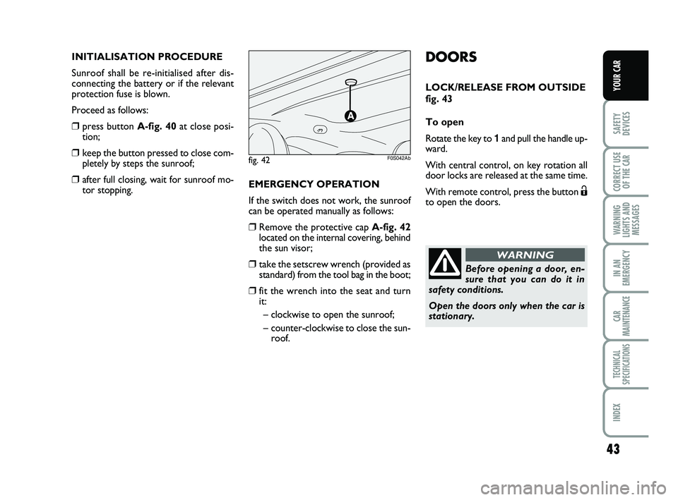
❒Remove the protective cap A-fig. 42
located on the internal covering, behind
the sun visor;
❒take the setscrew wrench (provided as
standard) from the tool bag in the boot;
❒fit the wrench into the seat and turn
it:
– clockwise to open the sunroof;
– counter-clockwise to close the sun-
roof.
fig. 42F0S042Ab
023-045 ABARTH 500 GB 29-04-2009 9:41 Pagina 43
Page 77 of 170
76
CORRECT USE
OF THE
CAR
WARNING
LIGHTS AND
MESSAGES
IN AN
EMERGENCY
CAR
MAINTENANCE
TECHNICAL
SPECIFICATIONS
INDEX
YOUR CAR
SAFETY
DEVICES
Do not rest the head, the
arms or the elbows on the
door, on the windows and on the win-
dow bag area to avoid injuries dur-
ing inflation.
Never lean head, arms and elbows
out of window.
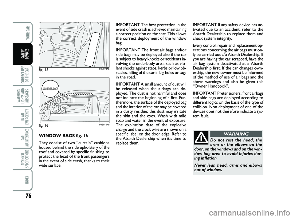
WARNINGWINDOW BAGS fig. 16
They consist of two “curtain” cushions
housed behind the side upholstery of the
roof and covered by specific finishing to
protect the head of the front passengers
in the event of side crash, thanks to their
wide surface.IMPORTANT The best protection in the
event of side crash is achieved maintaining
a correct position on the seat. This allows
the correct deployment of the window
bag.
IMPORTANT The front air bags and/or
side bags may be deployed also if the car
is subject to heavy knocks or accidents in-
volving the underbody area, such as vio-
lent shocks against steps, kerbs or low ob-
stacles, falling of the car in big holes or sags
in the road.
IMPORTANT A small amount of dust will
be released when the airbags are de-
ployed. The dust is not harmful and does
not indicate the beginning of a fire. Fur-
thermore, the surface of the deployed bag
and the interior of the car may be covered
in a dusty residue: this dust may irritate
the skin and the eyes. Wash with mild
soap and water in the event of exposure.
The expiration date of the explosive
charge and the clock wire are shown on a
specific label on the door edge. Refer to
the Abarth Dealership when it’s time to
replace them.
fig. 16F0S075Ab
fig. 15F0S074Ab
IMPORTANT If any safety device has ac-
tivated due to an accident, refer to the
Abarth Dealership to replace them and
check system integrity.
Every control, repair and replacement op-
erations concerning the air bags must on-
ly be carried out c/o Abarth Dealership. If
you are having the car scrapped, have the
air bag system deactivated at a Abarth
Dealership first. If the car changes own-
ership, the new owner must be informed
of the method of use of air bags and the
above warnings and also be given this
“Owner Handbook”.
IMPORTANT Pretensioners, front airbags
and side bags are deployed according to
different logics on the basis of the type of
collision. Non deployment of one of the
devices does not therefore indicate a sys-
tem fault.
063-078 ABARTH 500 GB 29-04-2009 9:42 Pagina 76
Page 107 of 170

106
WARNING
LIGHTS AND
MESSAGES
CAR
MAINTENANCE
TECHNICAL
SPECIFICATIONS
IINDEX
YOUR CAR
SAFETY
DEVICES
CORRECT USE
OF THE
CAR
IN AN
EMERGENCY
CYLINDER REPLACEMENT
PROCEDURE
To replace the cylinder proceed as fol-
lows:
❒disconnect connection A-fig. 18;
❒turn counter-clockwise the cylinder to
replace and raise it;
fig. 18F0S091Ab
❒fit the new cylinder and turn it clock-
wise;
❒connect connection Ato the cylinder
and fit the transparent tube Binto the
proper space.
095-122 ABARTH 500 GB 29-04-2009 9:43 Pagina 106
Page 110 of 170

109
WARNING
LIGHTS AND
MESSAGES
CAR
MAINTENANCE
TECHNICAL
SPECIFICATIONS
INDEX
YOUR CAR
SAFETY
DEVICES
CORRECT USE
OF THE
CAR
IN AN
EMERGENCY
BULB TYPES fig. 19
Various types of bulbs are fitted to your
car:
A All glass bulb: clipped into place. Pull
to extract.
B Bayonet bulbs: to remove this type
of bulb from its holder, press the bulb
and turn it anticlockwise.
C Cylindrical bulbs: release from the
contacts to extract.
D Halogen bulbs: release the fastening
clip from the corresponding seat to re-
move the lamp.
E Halogen bulbs: release the fastening
clip from the corresponding seat to re-
move the lamp. IMPORTANT A slight misting may appear
on the internal surface of the headlight:
this does not indicate a fault and is caused
by low temperature and the degree of hu-
midity in the air. Misting will rapidly dis-
appear when the headlights are switched
on. The presence of drops inside the head-
lights indicates infiltration of water. Go to
a Abarth Dealership.
F0S092Abfig. 19
095-122 ABARTH 500 GB 29-04-2009 9:43 Pagina 109
Page 112 of 170

111
WARNING
LIGHTS AND
MESSAGES
CAR
MAINTENANCE
TECHNICAL
SPECIFICATIONS
INDEX
YOUR CAR
SAFETY
DEVICES
CORRECT USE
OF THE
CAR
IN AN
EMERGENCY
DIRECTION INDICATORS
Front
To change the bulb, proceed as follows:
❒remove the protecting rubber cap men-
tioned above;
❒turn the bulb holder clockwise A-fig.
22and withdraw it;
❒remove the snap-fitted bulb and replace
it;
❒refit the bulb holder Aby turning it
clockwise and locking it properly;
❒reinstall the rubber cap;
IF AN EXTERIOR LIGHT
BURNS OUT
For the type of bulb and power rating, see
“When needing to change a bulb”.
FRONT LIGHT CLUSTERS
The front light clusters contain sidelights,
dipped beam, main beam and direction in-
dicator bulbs.
Operating from the engine compartment
remove the rubber cap A-fig. 20to ac-
cess the direction indicators; remove the
rubber cap B-fig. 20 to access the bulbs
of the dipped beam headlights.
To access the bulbs of the sidelights/day-
lights and of the main beams, after fully
steering the wheels open the guard door
C-fig. 21on the wheelhouse at the level
of the lights, then remove the rubber cap
D-fig. 21.
fig. 20F0S093Ab
fig. 21F0S094Ab
fig. 22F0S095Ab
095-122 ABARTH 500 GB 29-04-2009 9:43 Pagina 111
Page 113 of 170

112
WARNING
LIGHTS AND
MESSAGES
CAR
MAINTENANCE
TECHNICAL
SPECIFICATIONS
IINDEX
YOUR CAR
SAFETY
DEVICES
CORRECT USE
OF THE
CAR
IN AN
EMERGENCY
MAIN BEAM HEADLIGHTS
To change the bulb, proceed as follows:
❒remove the protecting rubber cap men-
tioned above;
❒release the two bulb holding clips A-
fig. 25;
❒remove the bulb and replace it;
❒fit the new bulb, making the outline of
the metallic part coincide with the
grooves on the reflector, then hook
back the bulb holding clips;
❒reinstall the rubber cap; DIPPED BEAM HEADLIGHTS
To change the bulb, proceed as follows:
❒remove the protecting rubber cap men-
tioned above;
❒press the fastener A-fig. 24and extract
the bulb holder;
❒remove the snap-fitted bulb and replace
it;
❒refit the cap locking it properly.
❒reinstall the rubber cap; Side
To change the bulb, proceed as follows:
❒prise in the point indicated by the ar-
row, so as to compress the fixing clip
and extract the assembly B-fig. 23;
❒turn the bulb holder counterclockwise,
remove the snap-fitted bulb and replace
it;
❒reinstall the bulb holder into the lens,
then install the assembly Bmaking sure
that the fixing clip has clicked.
fig. 24F0S097Abfig. 25F0S098Abfig. 23F0S096Ab
095-122 ABARTH 500 GB 29-04-2009 9:43 Pagina 112
Page 114 of 170
113
WARNING
LIGHTS AND
MESSAGES
CAR
MAINTENANCE
TECHNICAL
SPECIFICATIONS
INDEX
YOUR CAR
SAFETY
DEVICES
CORRECT USE
OF THE
CAR
IN AN
EMERGENCY
SIDELIGHTS/
DAYLIGHT LIGHTS
To change the bulb, proceed as follows:
❒remove the protecting rubber cap men-
tioned above;
❒turn the bulb holder clockwise B-fig.
25and withdraw it;
❒remove the snap-fitted bulb and replace
it;
❒refit the bulb holder Bby turning it
clockwise and locking it properly;
❒reinstall the rubber cap;
FRONT FOG LIGHTS
(where provided)
IMPORTANT to replace the front fog
lights you must contact Abarth Dealership.
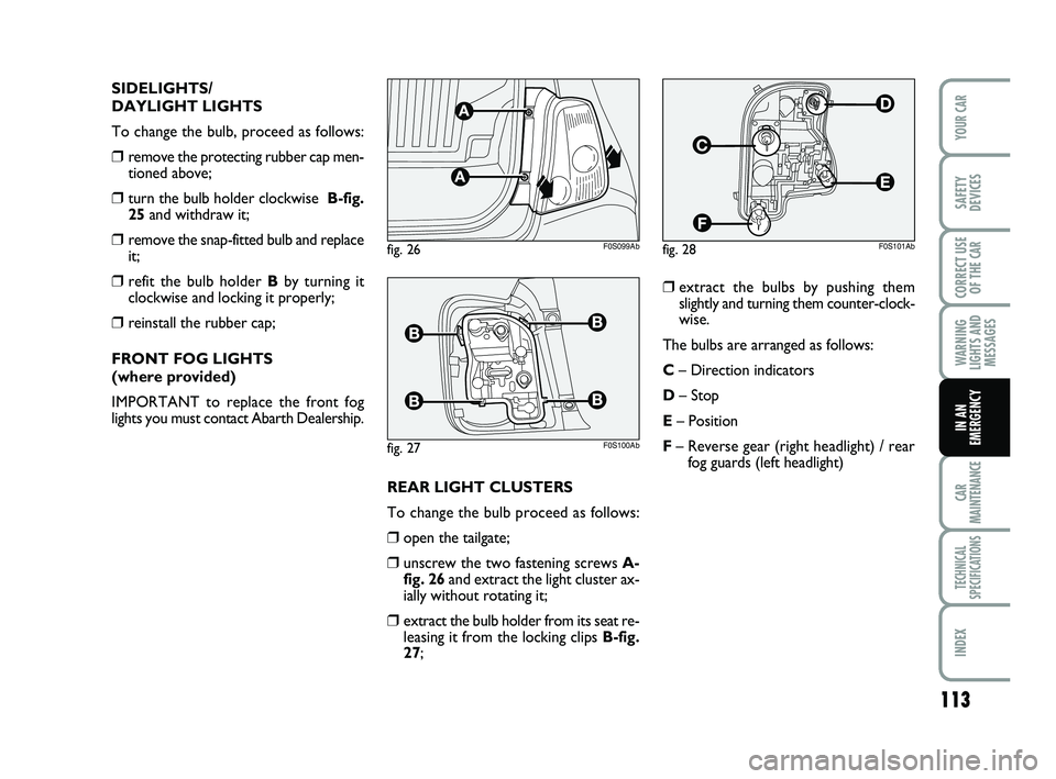
❒extract the bulbs by pushing them
slightly and turning them counter-clock-
wise.
The bulbs are arranged as follows:
C– Direction indicators
D– Stop
E– Position
F– Reverse gear (right headlight) / rear
fog guards (left headlight)
REAR LIGHT CLUSTERS
To change the bulb proceed as follows:
❒open the tailgate;
❒unscrew the two fastening screws A-
fig. 26and extract the light cluster ax-
ially without rotating it;
❒extract the bulb holder from its seat re-
leasing it from the locking clips B-fig.
27;
fig. 26F0S099Ab
fig. 27F0S100Ab
fig. 28F0S101Ab
095-122 ABARTH 500 GB 29-04-2009 9:43 Pagina 113