engine Abarth 500 2010 Owner handbook (in English)
[x] Cancel search | Manufacturer: ABARTH, Model Year: 2010, Model line: 500, Model: Abarth 500 2010Pages: 170, PDF Size: 3.04 MB
Page 2 of 170
Dear Customer,
Thank you for choosing Abarth and congratulations on your choice of a Abarth.
We prepared this booklet to enable you to know each detail of your Abarth and use it correctly. Please, read it carefully
before driving your car. You will find information, tips and important warnings regarding the driving of your car to help you derive
the maximum from the technological features of your Abarth.
You are recommended to read carefully the warnings and indications, marked with the respective symbols:
personal safety;
the car’s wellbeing;
environmental protection.
The enclosed Warranty Booklet lists the services that Abarth offers to its Customers:
❒the Warranty Certificate with terms and conditions for maintaining its validity
❒the range of additional services available to Abarth Customers.
Best regards and happy motoring!
The special features of the new 500 Abarth make the car captivating through its unmistakeable appearance,
stylish yet traditional and, at the same time, practical in terms of performance and safety thanks to the new
elements that have been introduced. The miniskirts, the rear spoiler and the inclined connector to the underbody
improve the drag coefficient, the geometry and road holding at speed. The twin exhaust pipes are fitted at the
sides of the incline at the specular outlets of a single transversely mounted silencer. The front and rear
symmetrical air intakes are practical and the first ones allow the flow of air for cooling the two specular
intercoolers, while the second ones permit the outlet of the flow at the rear. The introduction of the TTC
system (Torque Transfer Control), which improves the transfer of engine torque to the wheels, makes the
vehicle safer and more pleasant to drive, especially when cornering. Comfort is improved thanks to the introduction
of the anti-roll bar which involves a reduction in shock absorber pressure thereby making the vehicle less rigid.
Every feature of the 500 Abarth passenger compartment, from the turbo analogue pressure gauge, the
steering wheel with three spokes and shaped grips, the aluminium pedal assembly, the gear lever with an
ergonimically designed grip and the seats with head restraints built-into the backrest,
is designed to give the car a sporty appearance.
This Owner Handbook contains descriptions of the various new 500 Abarth trim levels therefore you should find
the information that relates to the version you have purchased.
001-022 ABARTH 500 GB 29-04-2009 9:40 Pagina 1
Page 5 of 170
4
SAFETY
DEVICES
CORRECT USE
OF THE
CAR
WARNING
LIGHTS AND
MESSAGES
IN AN
EMERGENCY
CAR
MAINTENANCE
TECHNICAL
SPECIFICATIONS
INDEX
YOUR CAR
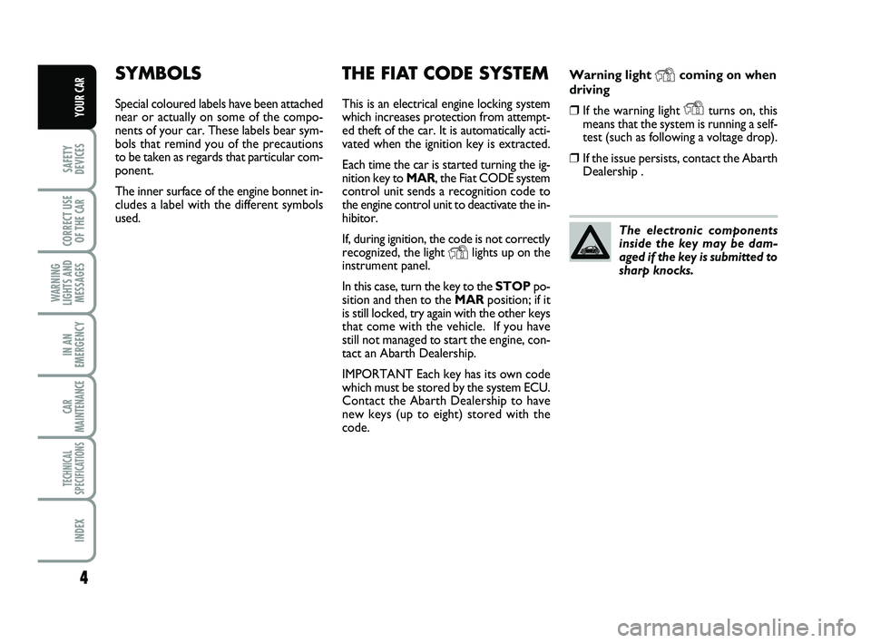
Warning light Ycoming on when
driving
❒If the warning light Yturns on, this
means that the system is running a self-
test (such as following a voltage drop).
❒If the issue persists, contact the Abarth
Dealership .
SYMBOLS
Special coloured labels have been attached
near or actually on some of the compo-
nents of your car. These labels bear sym-
bols that remind you of the precautions
to be taken as regards that particular com-
ponent.
The inner surface of the engine bonnet in-
cludes a label with the different symbols
used.
THE FIAT CODE SYSTEM
This is an electrical engine locking system
which increases protection from attempt-
ed theft of the car. It is automatically acti-
vated when the ignition key is extracted.
Each time the car is started turning the ig-
nition key to MAR, the Fiat CODE system
control unit sends a recognition code to
the engine control unit to deactivate the in-
hibitor.
If, during ignition, the code is not correctly
recognized, the light
Ylights up on the
instrument panel.
In this case, turn the key to the STOPpo-
sition and then to the MARposition; if it
is still locked, try again with the other keys
that come with the vehicle. If you have
still not managed to start the engine, con-
tact an Abarth Dealership.
IMPORTANT Each key has its own code
which must be stored by the system ECU.
Contact the Abarth Dealership to have
new keys (up to eight) stored with the
code.The electronic components
inside the key may be dam-
aged if the key is submitted to
sharp knocks.
001-022 ABARTH 500 GB 29-04-2009 9:40 Pagina 4
Page 9 of 170
8
SAFETY
DEVICES
CORRECT USE
OF THE
CAR
WARNING
LIGHTS AND
MESSAGES
IN AN
EMERGENCY
CAR
MAINTENANCE
TECHNICAL
SPECIFICATIONS
INDEX
YOUR CAR
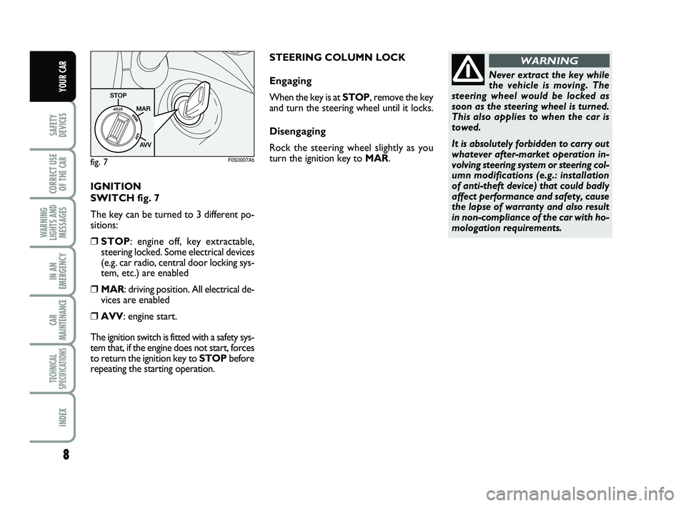
IGNITION
SWITCH fig. 7
The key can be turned to 3 different po-
sitions:
❒STOP: engine off, key extractable,
steering locked. Some electrical devices
(e.g. car radio, central door locking sys-
tem, etc.) are enabled
❒MAR: driving position. All electrical de-
vices are enabled
❒AVV: engine start.
The ignition switch is fitted with a safety sys-
tem that, if the engine does not start, forces
to return the ignition key to STOPbefore
repeating the starting operation.
Never extract the key while
the vehicle is moving. The
steering wheel would be locked as
soon as the steering wheel is turned.
This also applies to when the car is
towed.
It is absolutely forbidden to carry out
whatever after-market operation in-
volving steering system or steering col-
umn modifications (e.g.: installation
of anti-theft device) that could badly
affect performance and safety, cause
the lapse of warranty and also result
in non-compliance of the car with ho-
mologation requirements.
WARNING
fig. 7F0S0007Ab
STEERING COLUMN LOCK
Engaging
When the key is at STOP, remove the key
and turn the steering wheel until it locks.
Disengaging
Rock the steering wheel slightly as you
turn the ignition key to MAR.
001-022 ABARTH 500 GB 29-04-2009 9:40 Pagina 8
Page 10 of 170
9
SAFETY
DEVICES
CORRECT USE
OF THE
CAR
WARNING
LIGHTS AND
MESSAGES
IN AN
EMERGENCY
CAR
MAINTENANCE
TECHNICAL
SPECIFICATIONS
INDEX
YOUR CAR
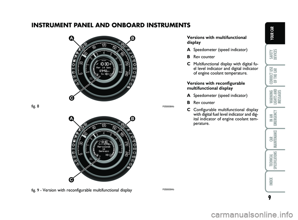
INSTRUMENT PANEL AND ONBOARD INSTRUMENTS
F0S0008Ab
F0S0009Ab
Versions with multifunctional
display
ASpeedometer (speed indicator)
BRev counter
CMultifunctional display with digital fu-
el level indicator and digital indicator
of engine coolant temperature.
Versions with reconfigurable
multifunctional display
ASpeedometer (speed indicator)
BRev counter
CConfigurable multifunctional display
with digital fuel level indicator and dig-
ital indicator of engine coolant tem-
perature.
fig. 8
fig. 9 -
Version with reconfigurable multifunctional display
001-022 ABARTH 500 GB 29-04-2009 9:40 Pagina 9
Page 12 of 170
11
SAFETY
DEVICES
CORRECT USE
OF THE
CAR
WARNING
LIGHTS AND
MESSAGES
IN AN
EMERGENCY
CAR
MAINTENANCE
TECHNICAL
SPECIFICATIONS
INDEX
YOUR CAR
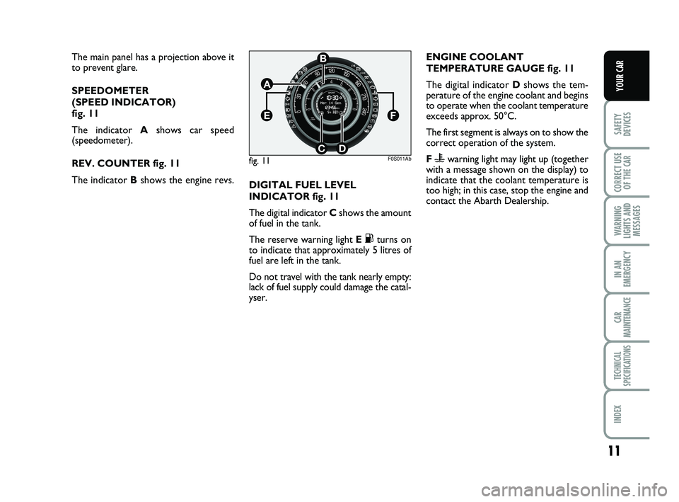
The main panel has a projection above it
to prevent glare.
SPEEDOMETER
(SPEED INDICATOR)
fig. 11
The indicator Ashows car speed
(speedometer).
REV. COUNTER fig. 11
The indicator Bshows the engine revs.
fig. 11
B
A
CD
EF
F0S011Ab
DIGITAL FUEL LEVEL
INDICATOR fig. 11
The digital indicator C shows the amount
of fuel in the tank.
The reserve warning light E
Kturns on
to indicate that approximately 5 litres of
fuel are left in the tank.
Do not travel with the tank nearly empty:
lack of fuel supply could damage the catal-
yser.ENGINE COOLANT
TEMPERATURE GAUGE fig. 11
The digital indicator Dshows the tem-
perature of the engine coolant and begins
to operate when the coolant temperature
exceeds approx. 50°C.
The first segment is always on to show the
correct operation of the system.
F
uwarning light may light up (together
with a message shown on the display) to
indicate that the coolant temperature is
too high; in this case, stop the engine and
contact the Abarth Dealership.
001-022 ABARTH 500 GB 29-04-2009 9:40 Pagina 11
Page 13 of 170
12
SAFETY
DEVICES
CORRECT USE
OF THE
CAR
WARNING
LIGHTS AND
MESSAGES
IN AN
EMERGENCY
CAR
MAINTENANCE
TECHNICAL
SPECIFICATIONS
INDEX
YOUR CAR
MULTIFUNCTIONAL
DISPLAY AND
RECONFIGURABLE
MULTIFUNCTIONAL
DISPLAY
(for versions/markets, where provided)
The car can be equipped with the multi-
functional/multifunctional reconfigurable
display that, according to the settings
made, will show useful information nec-
essary when driving.
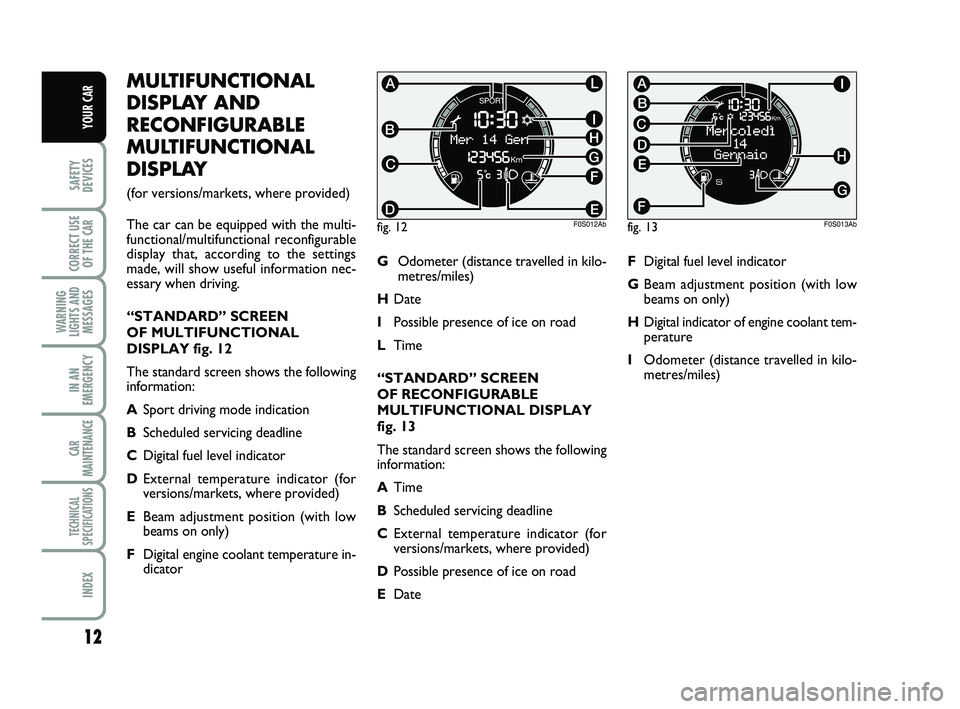
“STANDARD” SCREEN
OF MULTIFUNCTIONAL
DISPLAY fig. 12
The standard screen shows the following
information:
ASport driving mode indication
BScheduled servicing deadline
CDigital fuel level indicator
DExternal temperature indicator (for
versions/markets, where provided)
EBeam adjustment position (with low
beams on only)
FDigital engine coolant temperature in-
dicatorGOdometer (distance travelled in kilo-
metres/miles)
HDate
IPossible presence of ice on road
LTime
“STANDARD” SCREEN
OF RECONFIGURABLE
MULTIFUNCTIONAL DISPLAY
fig. 13
The standard screen shows the following
information:
ATime
BScheduled servicing deadline
CExternal temperature indicator (for
versions/markets, where provided)
DPossible presence of ice on road
EDate
fig. 12
I
E
F
G
L
H
D
B
C
A
F0S012Ab
FDigital fuel level indicator
GBeam adjustment position (with low
beams on only)
HDigital indicator of engine coolant tem-
perature
IOdometer (distance travelled in kilo-
metres/miles)
fig. 13
C
B
G
A
H
I
F
D
E
F0S013Ab
001-022 ABARTH 500 GB 29-04-2009 9:40 Pagina 12
Page 22 of 170
21
SAFETY
DEVICES
CORRECT USE
OF THE
CAR
WARNING
LIGHTS AND
MESSAGES
IN AN
EMERGENCY
CAR
MAINTENANCE
TECHNICAL
SPECIFICATIONS
INDEX
YOUR CAR
TRIP COMPUTER
General features
The “Trip computer” is used to display in-
formation on car operation when the key
is turned to MAR. This function allows to
define two separate trips called “Trip A”
and “Trip B” for monitoring the car’s
“complete mission” in a reciprocally in-
dependent manner.
Both functions are resettable (reset - start
of new mission).
“Trip A” shall be used to display the fig-
ures relating to:
– Range
– Trip distance
– Average consumption
– Instant consumption
– Average speed
– Travel time (driving time).“Trip B” shall be used to display the fig-
ures relating to:
– Trip distance B
– Average consumption B
– Average speed B
– Travel time B (driving time).
Note“Trip B” functions may be exclud-
ed (see “Trip B on”). “Range” and “In-
stantaneous consumption” cannot be re-
set.
Values displayed
Range
The distance that can be travelled with the
fuel in the tank is displayed, with the the-
ory that driving will continue in the same
conditions. The display will show the read-
ing “----” when the following events take
place:
– value lower than 50 km (or 30 mi)
– the car is parked with the engine run-
ning for a long time.IMPORTANT The range depends on sev-
eral factors: driving style (see “Driving
style” in “Starting and driving”), type of
route (motorway, urban cycle, mountain
roads, etc…), conditions of use of the car
(load, tyre pressure, etc…). Trip planning
must take into account the above notes.
Distance travelled
This value shows the distance covered
from the start of the new mission.
Average consumption
This value shows the approximate aver-
age consumption from the start of the
new mission.
Instant consumption
This indicates the fuel consumption. The val-
ue is constantly updated. The message
“----” will appear on the display if the car is
parked with the engine running.
001-022 ABARTH 500 GB 29-04-2009 9:40 Pagina 21
Page 26 of 170
25
SAFETY
DEVICES
CORRECT USE
OF THE
CAR
WARNING
LIGHTS AND
MESSAGES
IN AN
EMERGENCY
CAR
MAINTENANCE
TECHNICAL
SPECIFICATIONS
INDEX
YOUR CAR
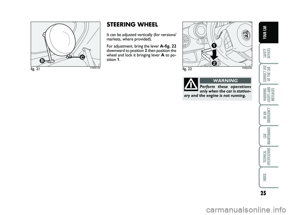
STEERING WHEEL
It can be adjusted vertically (for versions/
markets, where provided).
For adjustment. bring the lever A-fig. 22
downward to position 2then position the
wheel and lock it bringing lever Ato po-
sition 1.
fig. 21F0S021Abfig. 22F0S022Ab
Perform these operations
only when the car is station-
ary and the engine is not running.
WARNING
023-045 ABARTH 500 GB 29-04-2009 9:41 Pagina 25
Page 34 of 170
33
SAFETY
DEVICES
CORRECT USE
OF THE
CAR
WARNING
LIGHTS AND
MESSAGES
IN AN
EMERGENCY
CAR
MAINTENANCE
TECHNICAL
SPECIFICATIONS
INDEX
YOUR CAR
∂to the vents in the feet area (front
seats). The natural tendency of hot
air to spread upwards, allows to
warm the passenger compartment
up as quickly as possible, providing
an immediate feeling of warmth.
∂+μdistribution between feet area
vents (warmer air) and dashboard
vents (cooler air).
∂+´distribution between feet area
vents and windscreen and front
side window vents). This distribu-
tion allows an adequate warming of
the passenger compartment and
prevents the windows from mist-
ing up.
The set distribution is shown by the LEDs
on the selected buttons.
To restore automatic air distribution con-
trol, press button AUTO.
Button
-- L
Front window fast
demisting/defrosting button
Pressing the button
-the system acti-
vates all the functions required for fast
demisting/defrosting:
❒compressor switch on (if climatic con-
ditions are suitable);
❒air recycle off;
❒air temperature set to maximum (HI);
❒fan speed selection depending on
coolant temperature;
❒air flow toward the windshield and the
front side windows;
❒heated rear window on.
IMPORTANT The function remains active
for about 3 minutes since the engine
coolant temperature exceeds 50°C (for
petrol versions) or 35°C (for Diesel ver-
sions).
LOOKING AFTER THE SYSTEM
Run the climate control system for at least
10 minutes every month during the win-
ter.
Have the system inspected at a Abarth
Dealership before the summer.The system uses R134a
coolant which, in the event of
accidental leaks, is not dan-
gerous for the environment.
Do not use R12 coolant, not suitable
for the components of the system.
HEATED REAR WINDOW
DEMISTER/DEFROSTER
Press the button Mto activate this func-
tion; its activation is shown by a warning
light on the instrument panel.
The function is automatically deactivated
after about 20 minutes. To turn off the
function beforehand, press again the but-
ton
(.
IMPORTANT Do not apply stickers on
the internal side of the rear window over
the filaments of the heated rear window,
to avoid damaging it.
023-045 ABARTH 500 GB 29-04-2009 9:41 Pagina 33
Page 37 of 170
36
SAFETY
DEVICES
CORRECT USE
OF THE
CAR
WARNING
LIGHTS AND
MESSAGES
IN AN
EMERGENCY
CAR
MAINTENANCE
TECHNICAL
SPECIFICATIONS
INDEX
YOUR CAR
Ceiling light timing (central
position of the lens)
Three different switch on modes are fore-
seen:
❒when opening one door, a three minute
timing is set;
❒when removing the key from the igni-
tion switch within two minutes from
engine switch off, a 10 second timing
is set;
❒when doors are unlocked (either with
remote control or with key on driver
side door), a 10 second timing is set.
Three modes are foreseen for switch off:
❒when closing all doors, a three minute
timing is set; The timing is disabled if the
key is moved to MAR;
❒when doors are locked (either with re-
mote control or with key on driver side
door), the ceiling light turns off.
❒the internal lights turn off after 15 min-
utes to avoid battery drain
BOOT LIGHT
The lamp comes on automatically when the
luggage compartment is opened and goes
out when it is closed.
CEILING LIGHTS
FRONT CEILING LIGHT
The lens can be set to three positions:
❒right side pressed: light always on
❒left side pressed: light always off
❒central position (neutral): the light turns
on and off when the doors are opened
or closed.
IMPORTANT Before getting out of the
car, make sure the switch is on the cen-
tral position: ensure that lights are off with
doors closed in order to avoid draining
the battery.
On same versions, light switch on and off
occur only when the front driver side door
is opened or closed.
When the doors are unlocked using the re-
mote control, a 10 second timing turns on.
When the doors are locked using the re-
mote control, the ceiling light turns off. REAR WINDOW WIPER/
REAR WINDOW WASHER
The device can work only when the igni-
tion key is on MAR.
Turn the knurled ring to
'to operate
the rear window wiper.
With the windscreen wiper active, rotate
the knurled ring to
'to activate the rear
window wiper which, in this case, oper-
ates (in the different positions) in synch
with the windscreen wiper, yet with half
its frequency. With windscreen wiper ac-
tive, engaging reverse gear, the rear win-
dow wiper automatically turns on in slow
continuous mode.
It stops when the reverse gear is disen-
gaged.
“Smart washing” function
Pushing the stalk towards the dashboard
(unstable position) will activate the rear
window washer.
Keep the stalk pushed to activate with a
single movement the rear window wash-
er jet and the rear window wiper; the lat-
ter automatically turns on if you keep the
stalk pushed for over half a second.
The rear window wiper stops operating
a few strokes after releasing the stalk; a
further “cleaning stroke”, after a few sec-
onds, completes the wiping operation.
Do not use the rear window
wiper to remove layers of
snow or ice from the rear win-
dow. In such conditions, the
rear window wiper may be subjected to
excessive stress and the motor protec-
tion which prevents operation for a few
seconds may trip. If the issue persists,
contact the Abarth Dealership.
023-045 ABARTH 500 GB 29-04-2009 9:41 Pagina 36