warning light Abarth 500 2016 Owner handbook (in English)
[x] Cancel search | Manufacturer: ABARTH, Model Year: 2016, Model line: 500, Model: Abarth 500 2016Pages: 215, PDF Size: 19.08 MB
Page 57 of 215
 EBD (Electronic
Brakeforce Distribution)
SYSTEM
This system (which cannot be
deactivated) recognises emergency
braking conditions according to the
speed of operation of the brake pedal
and provides an")
EBD (Electronic
Brakeforce Distribution)
SYSTEM
This system (which cannot be
deactivated) recognises emergency
braking conditions according to the
speed of operation of the brake pedal
and provides an additional hydraulic
braking pressure to support that
provided by the driver. This allows
faster and more powerful operation of
the braking system.
ABS
This system, which is an integral part of
the braking system, prevents one or
more wheels from locking and slipping
on all road surface conditions,
irrespective of the intensity of the
braking action, ensuring that the car
can be controlled even during
emergency braking thus optimising
stopping distances.The system intervenes when braking
and the wheels are about to lock,
typically in emergency braking or
low-grip conditions, when locking may
be more frequent.
The system also improves control and
stability of the car when braking on a
surface where the grip of the left and
right wheels varies, or on corners.
System intervention
A slight pulsing of the brake pedal and
noise indicates the intervention of the
ABS: this is completely normal when
the system intervenes
31) 32) 33) 34) 35) 36) 37)
ASR (AntiSlip
Regulation) SYSTEM
This is an integral part of the ESC
system and automatically operates in
the event of one or both drive wheels
slipping, loss of grip on wet roads
(aquaplaning) and acceleration
on slippery, snowy or icy roads, etc.Depending on the slipping conditions,
two different control systems are
activated:
ŌØÆif the slipping involves both drive
wheels, the ASR system intervenes,
reducing the power transmitted by
the engine;
ŌØÆif the slipping only involves one of the
drive wheels, it also intervenes
automatically, braking the wheel that
is slipping.
System intervention
This is indicated by the flashing of the
warning light on the instrument panel,
to inform the driver that the car is in
critical stability and grip conditions.38) 39) 40) 41)
53
Page 59 of 215
 TTC SYSTEM (Torque
Transfer Control)
It is an integral part of the ESC system.
This system improves the transfer of
drive torque to the wheels,
guaranteeing safer and more sporty
driving, especially w")
TTC SYSTEM (Torque
Transfer Control)
It is an integral part of the ESC system.
This system improves the transfer of
drive torque to the wheels,
guaranteeing safer and more sporty
driving, especially when cornering, far
more able to prevent understeer.
System activation
It is turned off by pressing the button
again or when the vehicle is switched
off (ignition key in the OFF position).
WARNING
31) When the ABS intervenes and
you feel the brake pedal pulsating,
do not reduce the pressure, but
hold it down firmly and
confidently; in doing so you will
brake in the shortest distance
possible, depending on the
current road conditions.
32) To obtain the maximum
efficiency of the braking system, a
bedding-in period of about 500
km is needed: during this period it
is better to avoid sharp, repeated
and prolonged braking.
33) If the ABS system intervenes,
this indicates that the traction
of the tyres on the road is about
to reach its limit. You must slow
down to a speed compatible with
the available traction.
34) The ABS cannot overrule the
natural laws of physics, and
cannot increase the grip available
according to the condition of
the road.35) The ABS cannot prevent
accidents, including those due to
excessive speed on corners,
driving on low-grip surfaces or
aquaplaning.
36) The capability of the ABS must
never be tested irresponsibly and
dangerously, in such a way as
to compromise personal safety
and the safety of others.
37) For the correct operation of the
ABS, it is essential that the tyres
are of the same make and type on
all wheels, in perfect condition
and, above all, of the specified
type and dimensions.
38) For the correct operation of the
ASR system, it is essential that
the tyres are of the same make
and type on all wheels, in perfect
condition and, above all, of the
specified type and dimensions.
39) The ASR system cannot overrule
the natural laws of physics, and
cannot increase the grip available
according to the condition of
the road.
40) The ASR system cannot prevent
accidents, including those due to
excessive speed on corners,
driving on low-grip surfaces or
aquaplaning.
60AB0A0226
55
The system is activated by pressing
button A fig. 60 in the dashboard.
Activation is signalled by the LED in the
TTC button lighting up.
Page 61 of 215
 Low tyre pressure
The system warns the driver if one or
more tyres are flat by switching on
the
warning light on the instrument
panel.
The display will also show the following
information:
ŌØÆone or m")
Low tyre pressure
The system warns the driver if one or
more tyres are flat by switching on
the
warning light on the instrument
panel.
The display will also show the following
information:
ŌØÆone or morethan one tyre flat: the
display will show ŌĆ£KOŌĆØ beside the tyres
fig. 62 along with a warning message.
If the system does not recognise the
pressure value of one or more tyres, the
display will show dashes "ŌĆō ŌĆō"
This indication is displayed also when
turning the engine off and on again until
the RESET procedure is carried out.
RESET PROCEDURE
The iTPMS needs an initial "self-
learning" phase (with length depending
on the driving style and road conditions:
optimal conditions being driving on a
straight road at 80 km/h for at least 20
minutes) which starts when the Reset
procedure is carried out.The Reset procedure must be carried
out:
ŌØÆwhenever the tyre pressure is
modified;
ŌØÆwhen even only one tyre is changed;
ŌØÆwhen tyres are rotated/inverted;
ŌØÆwhen the space-saver wheel is fitted.
Before carrying out the RESET
pressure values specified in the inflation
pressure table (see "Wheels" paragraph
in the "Technical specifications"
chapter).
If the RESET is not carried out, in all
above cases, the
warning light may
give false indications on one or more
tyres.
To carry out the RESET procedure, with
the vehicle stopped and the ignition
key at MAR, use the setup menu (see
the description of the "Menu items"
paragraph).
At the end of the Reset procedure the
display will show the "Reset saved"
message, indicating that the self-
learning has been started.
61AB0A0123
62AB0A0217
57
p. rocedure, inflate the tyres to the rated
Page 62 of 215
 OPERATING CONDITIONS
48), 49), 50), 51), 52), 53)
The system is active for speeds above
15 km/h.
In a few situations such as sporty
driving, particular conditions of the road
surface (e.g. icy, snowy,")
OPERATING CONDITIONS
48), 49), 50), 51), 52), 53)
The system is active for speeds above
15 km/h.
In a few situations such as sporty
driving, particular conditions of the road
surface (e.g. icy, snowy, unsurfaced
roads...) the signalling may be delayed
or partial in detecting the contemporary
deflation of more than one tyre.
Under special conditions (e.g. car
loaded asymmetrically on one side,
damaged or worn tyre, fitting the
space-saver wheel, fitting snow chains,
fitting different tyres on the axles) the
system may give false indications or be
temporarily deactivated.
If the system is temporarily deactivated
the
warning light flashes for about
75 seconds and then is continuously
on; at the same time, the display shows
a warning message.
This indication is displayed also after
the engine has been switched off and
then on again if the correct operating
conditions are not restored.
WARNING
48) If the system signals a pressure
decrease on a specific tyre, it is
recommended to check the
pressure on all four tyres.
49) iTPMS does not relieve the
driver from the obligation to check
the tyre pressure every month; it
is not even to be considered a
replacing system for maintenance
or a safety system.
50) Tyre pressure must be checked
with tyres cold. Should it become
necessary for whatever reason
to check pressure with warm
tyres, do not reduce pressure
even though it is higher than the
prescribed value, but repeat the
check when tyres are cold.
51) The iTPMS cannot indicate
sudden tyre pressure drops (for
example when a tyre bursts).
In this case, stop the car, braking
with caution and avoiding abrupt
steering.
52) The system only warns that the
tyre pressure is low: it is not able
to inflate them.53) Insufficient tyre inflation
increases fuel consumption,
reduces the tread duration and
may affect the capacity to drive
safely.
58
GETTING TO KNOW YOUR CAR
Page 63 of 215
 EOBD SYSTEM
The EOBD (European On Board
Diagnosis system) carries out a
continuous diagnosis of the
components of the car related to
emissions. It also alerts the driver, by
turning on the warning lig")
EOBD SYSTEM
The EOBD (European On Board
Diagnosis system) carries out a
continuous diagnosis of the
components of the car related to
emissions. It also alerts the driver, by
turning on the warning light
on the
instrument panel together with relevant
message on the display, when these
components are no longer in peak
conditions (see chapter "Warning lights
and messages").
The goal of the system is to:
ŌØÆmonitor system efficiency
ŌØÆindicate an increase in emissions due
to vehicle malfunction
ŌØÆindicate the need to replace
damaged components.
The system also has a connector that
can be interfaced with appropriate
equipment, which makes it possible to
read the error codes stored in the
control unit together with a series of
specific parameters for engine
operation and diagnosis.
IMPORTANT After eliminating the
failure, to check the system completely,
Abarth Dealerships must run a bench
test and, if necessary, road tests which
may also call for a long journey.
DUALDRIVE
ELECTRIC POWER
STEERING
(for versions/markets, where provided)
OPERATION
This only operates with the ignition key
turned to MAR-ON and the engine
started.
Electric power steering allows the force
required at the steering wheel to be
adapted to the driving conditions.
IMPORTANT When turning the ignition
key quickly, full power steering
functionality can be achieved after a
few seconds.
When the SPORT function is turned on
(see "Controls" paragraph in this
chapter) the electric power steering
assistance is altered, increasing the
sensitivity of the steering wheel.
54) 55)
IMPORTANT During parking
manoeuvres requiring a lot of steering,
the steering may become harder: this is
normal and is due to the intervention
of the system to protect the electric
steering motor from overheating, so no
repair is required. When the car is
used again later on, the power steering
will work normally.
WARNING
54) It is absolutely forbidden to carry
out any after-market operation
involving steering system or
steering column modifications
(e.g. installation of anti-theft
device) that could adversely affect
performance and safety,
invalidate the warranty and also
result in the car not meeting
type-approval requirements.
55) Before servicing the car, switch
off the engine and remove the key
from the ignition switch to
activate the steering lock. This is
especially important when the car
wheels are not touching the
ground. If this is not possible (for
example if the key needs to be
turned to MAR-ON or the engine
must be running), remove the
main fuse that protects the
electric power steering.
59
Page 67 of 215
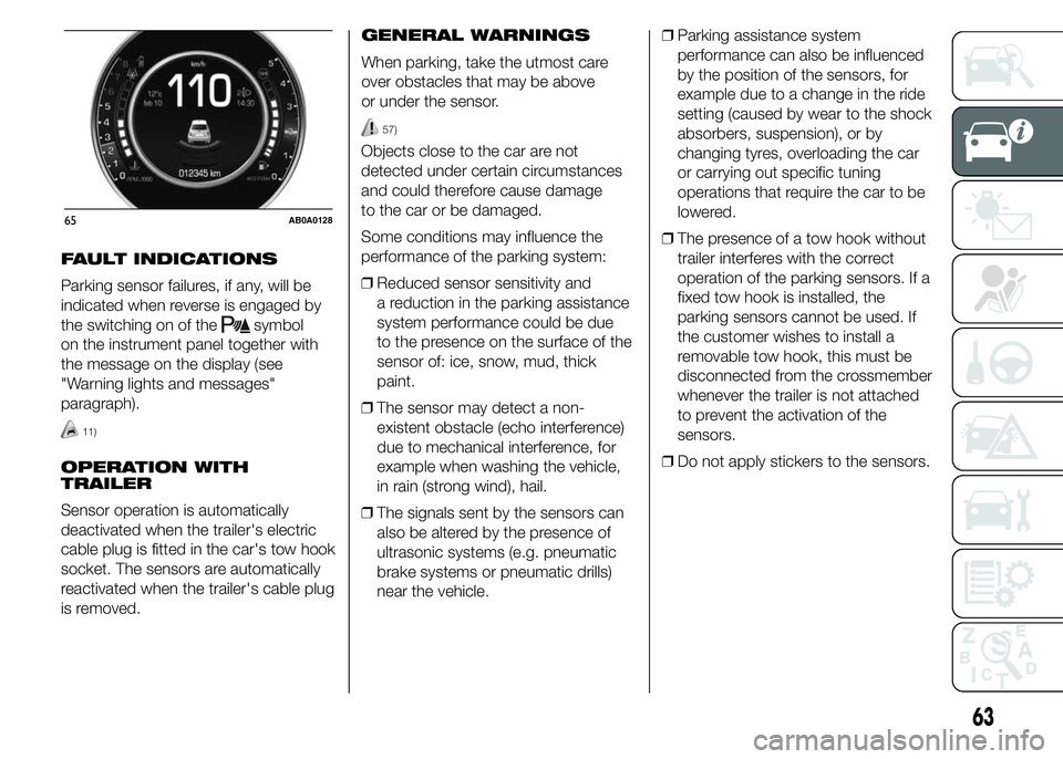
FAULT INDICATIONS
Parking sensor failures, if any, will be
indicated when reverse is engaged by
the switching on of the
symbol
on the instrument panel together with
the message on the display (see
"Warning lights and messages"
paragraph).
11)
OPERATION WITH
TRAILER
Sensor operation is automatically
deactivated when the trailer's electric
cable plug is fitted in the car's tow hook
socket. The sensors are automatically
reactivated when the trailer's cable plug
is removed.GENERAL WARNINGS
When parking, take the utmost care
over obstacles that may be above
or under the sensor.
57)
Objects close to the car are not
detected under certain circumstances
and could therefore cause damage
to the car or be damaged.
Some conditions may influence the
performance of the parking system:
ŌØÆReduced sensor sensitivity and
a reduction in the parking assistance
system performance could be due
to the presence on the surface of the
sensor of: ice, snow, mud, thick
paint.
ŌØÆThe sensor may detect a non-
existent obstacle (echo interference)
due to mechanical interference, for
example when washing the vehicle,
in rain (strong wind), hail.
ŌØÆThe signals sent by the sensors can
also be altered by the presence of
ultrasonic systems (e.g. pneumatic
brake systems or pneumatic drills)
near the vehicle.ŌØÆParking assistance system
performance can also be influenced
by the position of the sensors, for
example due to a change in the ride
setting (caused by wear to the shock
absorbers, suspension), or by
changing tyres, overloading the car
or carrying out specific tuning
operations that require the car to be
lowered.
ŌØÆThe presence of a tow hook without
trailer interferes with the correct
operation of the parking sensors. If a
fixed tow hook is installed, the
parking sensors cannot be used. If
the customer wishes to install a
removable tow hook, this must be
disconnected from the crossmember
whenever the trailer is not attached
to prevent the activation of the
sensors.
ŌØÆDo not apply stickers to the sensors.
65AB0A0128
63
Page 69 of 215
 FILLING THE TANK
To fill the tank completely, top-up twice
after the first click of the fuel supply
gun. Further top-ups could cause faults
in the fuel supply system.
FUEL TANK PLUG
Plug B fig. 66 is")
FILLING THE TANK
To fill the tank completely, top-up twice
after the first click of the fuel supply
gun. Further top-ups could cause faults
in the fuel supply system.
FUEL TANK PLUG
Plug B fig. 66 is fitted with loss
prevention device C which secures it to
flap A.
Unscrew plug B using the ignition key.
The sealing may cause a slight pressure
increase in the tank. A little breathing
off, while slackening the plug is
absolutely normal. When refuelling,
fasten the plug to the device inside the
flap as shown in fig. 66.
58)
WARNING
58) Keep naked flames or lit
cigarettes away from the fuel tank
filler: fire risk. Keep your face
away from the fuel filler to prevent
breathing in harmful vapours.
PROTECTING THE
ENVIRONMENT
The following devices are used for
reducing petrol fuel engine emissions:
ŌØÆthree-way catalytic converter
(catalytic converter)
ŌØÆoxygen sensors
ŌØÆevaporation control system.
59)
In addition, do not let the engine run,
even for a test, with one or more spark
plugs disconnected.
WARNING
59) Under operating conditions, the
catalytic converter becomes very
hot. Therefore, do not park the car
on flammable materials (grass,
dry leaves, pine needles, etc.): risk
of fire.66AB0A0058
65
Page 71 of 215
 KNOWING THE INSTRUMENT PANEL
This section of the handbook gives you
all the information you need to
understand, interpret and use the
instrument panel correctly.DISPLAY ...............................")
KNOWING THE INSTRUMENT PANEL
This section of the handbook gives you
all the information you need to
understand, interpret and use the
instrument panel correctly.DISPLAY ......................................... 68
MENU ITEMS .................................. 71
CONTROL PANEL AND
ON-BOARD INSTRUMENTS ........... 78
TRIP COMPUTER ........................... 80
WARNING LIGHTS AND
MESSAGES .................................... 83
- LOW BRAKE FLUID/HANDBRAKE
ENGAGED .......................................... 83
- EBD FAILURE .................................. 84
- AIRBAG FAILURE ............................. 84
- SEAT BELTS NOT FASTENED .......... 85
- ABS FAILURE ................................... 86
- PASSENGER SIDE AIRBAG
DEACTIVATED .................................... 86
- INJECTION/EOBD SYSTEM
FAILURE ............................................. 87
- ELECTRONIC STABILITY CONTROL
(ESC) SYSTEM ................................... 88
- SIDE LIGHTS AND DIPPED
HEADLIGHTS ..................................... 89
- FOLLOW ME HOME ........................ 89
- LEFT-HAND DIRECTION INDICATOR
............................................................ 89
- RIGHT-HAND DIRECTION
INDICATOR ........................................ 90
- MAIN BEAM HEADLIGHTS .............. 90
-FOG LIGHTS ..................................... 90
-REAR FOG LIGHT ............................. 90
-WORN BRAKE PADS ........................ 91
-DUALDRIVE ELECTRIC POWER
STEERING FAILURE ........................... 91
- INSUFFICIENT ENGINE OIL
PRESSURE/ENGINE OIL
DETERIORATED ................................. 92
-ENGINE OIL DETERIORATED ........... 93
- ENGINE COOLANT TEMPERATURE
TOO HIGH .......................................... 94-LOW BATTERY CHARGE .................. 95
-HILL HOLDER FAILURE .................... 95
- FIAT CODE SYSTEM FAILURE ......... 95
- FUEL RESERVE/LIMITED RANGE .... 96
- FUEL CUT-OFF ................................ 96
- FUEL CUT-OFF SYSTEM FAILURE ... 96
-INCOMPLETE DOOR LOCKING ........ 96
-EXTERIOR LIGHTS FAILURE ............. 97
-ASR SYSTEM ................................... 97
- POSSIBLE ICE ON ROAD ................ 97
- BRAKE LIGHT FAILURE ................... 97
- PARKING SENSOR FAILURE ........... 97
-iTPMS ............................................... 98
-SERVICE (SCHEDULED SERVICING)
............................................................ 99
-SPEED LIMIT EXCEEDED ................. 99
-ENGAGEMENT OF SPORT
FUNCTION ......................................... 99
67
Page 74 of 215
 NoteButtons+andŌĆōactivate different
functions according to the following
situations:
ŌØÆwithin the menu, they allow you to
scroll up or down through the
options;
ŌØÆduring setting operations, they
in")
NoteButtons+andŌĆōactivate different
functions according to the following
situations:
ŌØÆwithin the menu, they allow you to
scroll up or down through the
options;
ŌØÆduring setting operations, they
increase or decrease values.
NoteWhen one of the front doors is
opened, the display is activated
showing the time and mileage for a few
seconds.SETUP MENU
The menu comprises a series of
options which can be selected using
buttons+andŌĆōto access the different
selection and setting operations (Setup)
indicated below.
Some options have a submenu.
The menu can be activated by briefly
pressing the MENU button
. Single
presses on buttons+orŌĆōwill scroll
through the setup menu options.
Operating modes are different
according to the characteristics of the
option selected.
The menu comprises the following
functions:
ŌØÆMENU
ŌØÆLIGHTING
ŌØÆSPEED WARNING
ŌØÆHEADLIGHT SENSOR
ŌØÆTRIP B ACTIVATION
ŌØÆSET TIME
ŌØÆSET DATE
ŌØÆSEE RADIO
ŌØÆAUTOCLOSE
ŌØÆUNITS OF MEASUREMENT
ŌØÆLANGUAGE
ŌØÆWARNINGS VOLUMEŌØÆBUTTON VOLUME
ŌØÆSEAT BELT BUZZER
ŌØÆSERVICE
ŌØÆPASSENGER AIRBAG
ŌØÆDAYTIME RUNNING LIGHTS
ŌØÆTYRE RESET
ŌØÆEXIT MENU
Selecting an option from the main
menu without a submenu:
ŌØÆbriefly press the MENU button
to
select the main menu option to be
set;
ŌØÆpress buttons+orŌĆō(with single
presses) to select the new setting;
ŌØÆbriefly press the MENU button
to
store the new setting and to go back
to the same main menu option
selected previously.
Selecting an option from the main
menu with a submenu:
ŌØÆbriefly press the MENU button
to
display the first submenu option;
ŌØÆpress buttons+orŌĆō(with single
presses) to scroll through all the
submenu options;
ŌØÆbriefly press the MENU button
to
select the displayed submenu option
and to open the relevant setup menu;
70AB0A0002
70
KNOWING THE INSTRUMENT PANEL
Page 76 of 215
 Speed warning (Speed
limit)
With this function it is possible to set
the car speed limit (km/h or mph); when
this limit is exceeded the driver is
alerted.
To set the desired speed limit, proceed
as fo")
Speed warning (Speed
limit)
With this function it is possible to set
the car speed limit (km/h or mph); when
this limit is exceeded the driver is
alerted.
To set the desired speed limit, proceed
as follows:
ŌØÆbriefly press the MENU button
:
the display will show the words
(Speed Buzzer);
ŌØÆpress button+orŌĆōto select speed
limit activation ("On") or deactivation
("Off");
ŌØÆif the function is on, press+orŌĆōto
select the required speed limit and
then press MENU
to confirm.
NoteSetting is possible between 30
and 200 km/h, or 20 and 125 mph,
according to the previously set unit.
See the "Units of measurement
adjustment (Units of measurement)"
paragraph described below. The setting
will increase/decrease by five units
each time button+/ŌĆōis pressed. Hold
down the button+/ŌĆōto increase/
decrease the setting rapidly. Complete
the adjustment with single presses of
the button when you approach the
desired value.Press the MENU button
briefly to
return to the menu screen or hold
the button down to return to the
standard screen without storing.
To cancel the setting, proceed as
follows:
ŌØÆpress the MENU button
briefly:
("On") will flash on the display;
ŌØÆpress buttonŌĆō: ("Off") will flash on
the display;
ŌØÆpress the MENU button
briefly to
return to the menu screen or hold the
button down to return to the
standard screen without storing.Headlight sensor
(Automatic
headlight/dusk sensor
sensitivity adjustment)
(for versions/markets, where provided)
This function is used to turn the
headlights on or off according to
external lighting conditions.
The dusk sensor sensitivity can be
adjusted according to 3 levels (level 1=
minimum sensitivity, level 2= average
sensitivity, level 3 = maximum
sensitivity); the greater the sensitivity
set, the lower the variation in outside
light required to activate the lights (e.g.
with setting at level 3, the headlights
switch on earlier at sunset compared to
levels 1 and 2).
Proceed as follows to set:
ŌØÆpress the MENU button
briefly.
The level set previously flashes on
the display;
ŌØÆpress+orŌĆōto set the value;
ŌØÆpress the MENU button
briefly to
return to the menu screen or hold the
button down to return to the
standard screen without storing.
72
KNOWING THE INSTRUMENT PANEL