Abarth 500 2017 Owner handbook (in English)
Manufacturer: ABARTH, Model Year: 2017, Model line: 500, Model: Abarth 500 2017Pages: 192, PDF Size: 6.46 MB
Page 101 of 192
REPLACING FUSES
GENERAL INFORMATION
Fuses protect the electrical system:
they intervene (blow) in the event of a
failure or improper action on the
system.
122) 123) 124) 125) 126) 127)
To facilitate fuse replacement, use the
pliers hooked inside the fuse box lid on
the dashboard left-hand side.
Refer to the tables on the following
pages to identify the protective fuse.
FUSE LOCATION
Dashboard fuse box
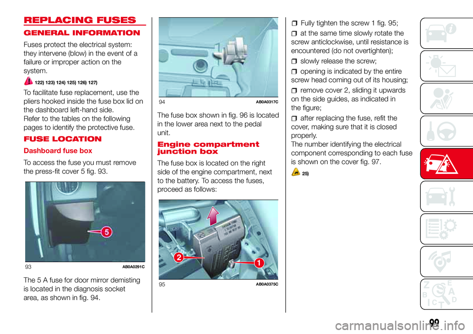
To access the fuse you must remove
the press-fit cover 5 fig. 93.
The 5 A fuse for door mirror demisting
is located in the diagnosis socket
area, as shown in fig. 94.The fuse box shown in fig. 96 is located
in the lower area next to the pedal
unit.
Engine compartment
junction box
The fuse box is located on the right
side of the engine compartment, next
to the battery. To access the fuses,
proceed as follows:
Fully tighten the screw 1 fig. 95;
at the same time slowly rotate the
screw anticlockwise, until resistance is
encountered (do not overtighten);
slowly release the screw;
opening is indicated by the entire
screw head coming out of its housing;
remove cover 2, sliding it upwards
on the side guides, as indicated in
the figure;
after replacing the fuse, refit the
cover, making sure that it is closed
properly.
The number identifying the electrical
component corresponding to each fuse
is shown on the cover fig. 97.
25)
93AB0A0291C
94AB0A0317C
12
95AB0A0375C
99
Page 102 of 192

DASHBOARD FUSE BOX
DEVICE PROTECTED FUSE AMPERE
Headlight alignment corrector F13
5(*)
Diagnosis socket, Uconnect, climate control, EOBD F36 15
Brake light switch, instrument panel node F37 5
Central door locking F38 15
Windscreen/rear window washer pump F43 15
Driver's side electric windows F47 20
(*) (where provided)
96AB0A0106C
100
IN AN EMERGENCY
Page 103 of 192
DEVICE PROTECTED FUSE AMPERE
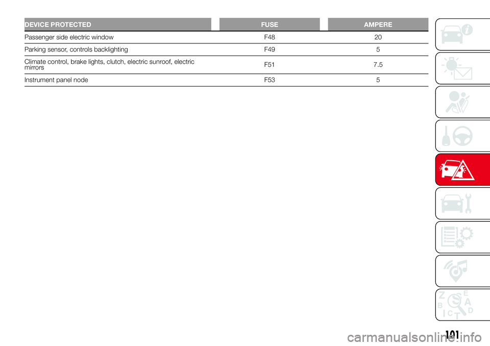
Passenger side electric window F48 20
Parking sensor, controls backlighting F49 5
Climate control, brake lights, clutch, electric sunroof, electric
mirrorsF51 7.5
Instrument panel node F53 5
101
Page 104 of 192

ENGINE COMPARTMENT JUNCTION BOX
DEVICE PROTECTEDFUSE AMPERE
HI-FIF02 20
Climate control electric fanF08 30
Headlight washersF09 30
HornsF10 10
Main-beam headlightsF14
10/15
(*)
Electric roof motorF15 20
(*) Only for versions equipped with Xenon gas discharge lamps
97AB0A0319C
102
IN AN EMERGENCY
Page 105 of 192
DEVICE PROTECTEDFUSE AMPERE
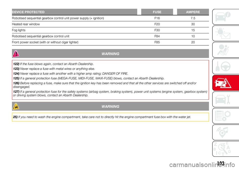
Robotised sequential gearbox control unit power supply (+ ignition) F16 7.5
Heated rear windowF20 30
Fog lightsF30 15
Robotised sequential gearbox control unit F84 10
Front power socket (with or without cigar lighter) F85 20
WARNING
122)If the fuse blows again, contact an Abarth Dealership.
123)Never replace a fuse with metal wires or anything else.
124)Never replace a fuse with another with a higher amp rating; DANGER OF FIRE.
125)If a general protection fuse (MEGA-FUSE, MIDI-FUSE, MAXI-FUSE) blows, contact an Abarth Dealership.
126)Before replacing a fuse, make sure that the ignition key has been removed and that all the other services are switched off and/or
disengaged.
127)If a general protection fuse for the safety systems (airbag system, braking system), power unit systems (engine system, gearbox system)
or driving system blows, contact an Abarth Dealership.
WARNING
25)If you need to wash the engine compartment, take care not to directly hit the engine compartment fuse box with the water jet.
103
Page 106 of 192

“Fix&Go” KIT
The kit is located in the luggage
compartment under the load platform
cover.
There is one or two of the following kits,
depending on the vehicle version:
“Fix&Go Airflat” kit
“Fix&Go Automatic” kit
“Fix&Go Airflat” KIT
The kit is composed of:
a spray bottle 1 fig. 98 with the
sealant, equipped with filling pipe 2,
separated by the compressor 3;
compressor 3 with pressure gauge,
fitting valve to couple the bottle 1, cable
with supply socket 4 and pipe 5 to
restore pressure (this is inside the body
as shown);
adhesive label on the spray bottle 1,
with the message "max. 80 km/h" to
be placed where the driver can easily
see it (for example on the dashboard)
after repairing the tyre;
instruction booklet, explaining the
quick and correct use of the Fix&Go;
a pair of protective gloves.TYRE REPAIRING AND
PRESSURE RESTORING
PROCEDURE
26) 27)
128)
Proceed as follows:
Position the vehicle in a safe and
suitable area and engage the
handbrake. Take the kit. Open the
compressor cover and insert the
sealant cartridge 1 (fig. 99) in its
compartment, pressing firmly
downwards. Remove the adhesive
speed label and apply it in a visible
position. Wear the protective gloves
provided. Remove the valve cap 5 from
the punctured tyre and connect and
firmly tighten the transparent sealing
fluid tube 3.
Ensure that the on-off button 1 (fig.
100) is in the off0position. Insert the
electrical connector in the car’s 12V
socket.
2
1
3
4
5
98AB0A0080C
1
5
3
2
4
99AB0A0083C
1
100AB0A0084C
104
IN AN EMERGENCY
Page 107 of 192

Move the on-off button 1 fig. 100 to
the onIposition to switch on the
compressor. When the pressure gauge
indicates the right pressure for the
car, switch off the compressor by
moving the on-off button1 to the0
position. If the pressure gauge 6 fig. 99
indicates a pressure lower than 1.8
bar / 26 psi 5 minutes after starting the
compressor, switch off the compressor,
disconnect the sealing fluid tube 3
(fig. 99) from the tyre valve, retighten
the valve cap and move the car about
10 meters to distribute the sealing
fluid in the tyre. Stop the car safely and
repeat the operation above until the
required pressure is reached. If after
other 5 min. from the compressor
ignition, the pressure gauge 6
still indicates a pressure lower than 1.8
bar / 26 psi, the TYRE IS TOO
DAMAGED AND CANNOT BE
REPAIRED. Disconnect, put the kit
back in its compartment and call
roadside assistance.If the required pressure is reached,
continue driving. Do not exceed
80 km/h. Avoid sudden acceleration or
braking. After driving for about 8 km /
5 miles, position the vehicle in a safe
and suitable area and engage the
handbrake. Take the kit, ensure that the
on-off button 1 (fig. 100) is in the0
position and insert the electrical
connector in the car’s 12V socket.
Remove the repaired tyre’s valve cap,
take out the black inflation tube and
screw it firmly onto the valve. Check the
tyre pressure shown on the pressure
gauge 6.
If the pressure is lower than 1.8 bar /
26 psi, the TYRE IS TOO DAMAGED
AND CANNOT BE REPAIRED.
Disconnect, put the kit back in its
compartment and call roadside
assistance.
If the pressure is equal to or higher
than 1.8 bar / 26 psi, switch on the
compressor to reach the required
pressure. Disconnect and replace the
kit in the specific compartment. Drive
carefully to a specialist or the
manufacturer’s dealership as soon as
possible.PRESSURE RESTORING
Take out the black inflation tube and
screw it firmly onto the tyre valve.
Follow the instructions given in fig. 98.
Press the button 2 fig. 101 to adjust
any tyre overpressure.
CARTRIDGE
REPLACEMENT
Only use Fix&Go original cartridges,
which can be purchased at the Abarth
Dealership. Press the release button
3 and lift it to remove the cartridge 1 fig.
101. Insert the new cartridge and
press it firmly downwards.
12
3
101AB0A0086C
105
Page 108 of 192

“Fix&Go Automatic” KIT
The kit includes:
one tank 1 fig. 102 containing the
sealing fluid, provided with: filler tube 2
and adhesive label 3 with the writing
"Max. 80 km/h”, to be attached in
a position easily visible to the driver (eg.
on the dashboard) after repairing the
tyre;
compressor 4 complete with
pressure gauge and connectors;
an instruction leaflet, to refer to for
prompt and correct use and that must
be then given to the personnel dealing
with the tyre treated with sealant;
a pair of gloves located in the side
compartment of the compressor;
some adaptors, for inflating different
elements.TYRE REPAIRING AND
PRESSURE RESTORING
PROCEDURE
26) 27)
128)
Proceed as follows:
place the vehicle in a safe and
suitable area, engaging the parking
brake. Take the kit from the specific
compartment. Remove the adhesive
label of speed 3 fig. 102 and apply it in
a visible position. Wear the protective
gloves provided. Remove the cap from
the valve of the punctured tyre and
connect and firmly tighten the
transparent tube of the sealing fluid 1
fig. 103;
ensure that the on-off button 1 fig.
104 is in0(OFF) position. If provided,
open the compressor cover, insert
the electrical connector in the car’s 12V
socket and start the car engine;
activate the compressor moving
on-off 1 button toI(ON) position fig.
104. When the pressure gauge 2
shows the car’s required pressure (see
section “Wheels” under “Technical
data” chapter), switch off the
compressor moving on-off button 1 to
0position. If after 5 minutes from the
compressor ignition, the pressure
gauge 2 indicates a pressure less than
1.8 bar / 26 psi, switch off the
compressor, disconnect the sealing
fluid tube from the tyre valve, re-screw
the valve cap and move the car about
10 meters to allow the distribution of
sealing fluid in the tyre. Stop the car
safely and repeat the operation above
until the required pressure is reached. If
after other 5 min. from the compressor
ignition, the pressure gauge 2 still
indicates a pressure lower than 1.8 bar
/ 26 psi, the TYRE IS TOO DAMAGED
AND CANNOT BE REPAIRED. Remove
and place the kit in its compartment
and contact an Abarth Dealership;
102AB0A0369C
103AB0A0370C
106
IN AN EMERGENCY
Page 109 of 192
if the required pressure is reached,
restart driving. Do not exceed 80 km/h.
Avoid sudden acceleration or braking.
After driving for about 8 km / 5 miles,
place the vehicle in a safe and suitable
area, engaging the parking brake.
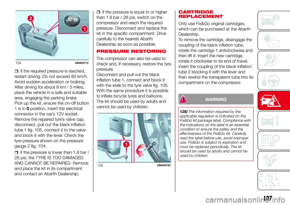
Pick up the kit, ensure the on-off button
1isin0position, insert the electrical
connector in the car’s 12V socket.
Remove the repaired tyre’s valve cap,
disconnect, pull out the black inflation
tube 1 fig. 105, connect it to the valve
and block it with the lever. Check the
tyre pressure shown on the pressure
gauge 2 fig. 104;
if the pressure is lower than 1.8 bar /
26 psi, the TYRE IS TOO DAMAGED
AND CANNOT BE REPAIRED. Remove
and place the kit in its compartment
and contact an Abarth Dealership;
if the pressure is equal to or higher
than 1.8 bar / 26 psi, switch on the
compressor and reach the required
pressure. Disconnect and replace the
kit in the specific compartment. Drive
carefully to the nearest Abarth
Dealership as soon as possible;
PRESSURE RESTORING
The compressor can also be used to
check and, if necessary, restore the tyre
pressure.
Disconnect and pull out the black
inflation tube 1, connect and block it
with the stalk to the tyre valve fig. 105.
With the same procedure it is possible
to inflate bicycle tyres and balloons.
The kit should be used by adults and
cannot be used by children.CARTRIDGE
REPLACEMENT
Only use Fix&Go original cartridges,
which can be purchased at the Abarth
Dealership.
To remove the cartridge, disengage the
coupling of the black inflation tube,
rotate the cartridge 1 anticlockwise and
then lift it. Insert the new cartridge,
rotate it clockwise to its end of travel,
insert the coupling of the black inflation
tube 2 blocking it with the lever and
then rewind the transparent tube into its
compartment on the compressor.
WARNING
128)The information required by the
applicable regulation is indicated on the
Fix&Go kit package label. Compliance with
the indications on the label is an essential
condition to ensure the safety and the
effectiveness of the Fix&Go kit. Carefully
read the label before use, avoid improper
use. Fix&Go is subject to expiration and
must be replaced periodically. The kit
should be used by adults and cannot be
used by children.
104AB0A0371C
105AB0A0372C
107
Page 110 of 192
WARNING
26)Show the package and the label to the
personnel charged with handling the tyre
treated with the tyre repair kit.
27)Fix&Go provides a temporary repair,
therefore the tyre must be examined and
repaired by a specialist as soon as
possible. The sealing fluid is effective at
temperatures between -40°C and +50°C. It
is possible to repair tyres which have
been damaged on tread up to a diameter
of 4mm; however, tyres damaged on
their side cannot be repaired. Before using
Fix&Go kit, ensure that the tyre isn't
excessively damaged and that the rim is in
good condition, otherwise do not use it
and call roadside assistance. Do not
remove foreign bodies from the tyre. Do
not let the compressor turned on for more
than 20 consecutive minutes - overheating
hazard.
JUMP STARTING
If thesymbol on the display turns
on constantly, contact an Abarth
Dealership immediately.
JUMP STARTING
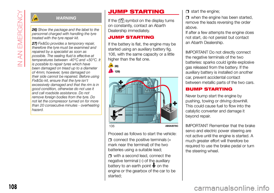
If the battery is flat, the engine may be
started using an auxiliary battery fig.
106, with the same capacity or a little
higher than the flat one.
28)
129)
Proceed as follows to start the vehicle:
connect the positive terminals (+
mark near the terminal) of the two
batteries using a suitable lead;
with a second lead, connect the
negative terminal (–) of the auxiliary
battery to an earth point
on the
engine or the gearbox of the car to be
started;
start the engine;
when the engine has been started,
remove the leads reversing the order
above.
If after a few attempts the engine does
not start, do not persist but contact
an Abarth Dealership.
IMPORTANT Do not directly connect
the negative terminals of the two
batteries: sparks could ignite explosive
gas released from the battery. If the
auxiliary battery is installed on another
car, prevent accidental contact
between metallic parts of the two cars.
BUMP STARTING
Never bump start the engine by
pushing, towing or driving downhill.
This could cause fuel to flow into the
catalytic converter and damage it
beyond repair.
IMPORTANT Remember that the brake
servo and electric power steering are
not active until the engine is started. A
much greater effort will therefore be
required to use the brake pedal or turn
the steering wheel.
106AB0A0078C
108
IN AN EMERGENCY