buttons Abarth 500 2017 Owner handbook (in English)
[x] Cancel search | Manufacturer: ABARTH, Model Year: 2017, Model line: 500, Model: Abarth 500 2017Pages: 192, PDF Size: 6.46 MB
Page 12 of 192
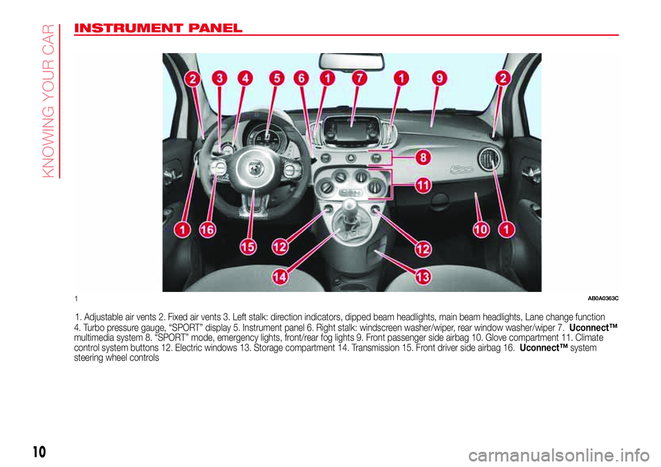
INSTRUMENT PANEL
1. Adjustable air vents 2. Fixed air vents 3. Left stalk: direction indicators, dipped beam headlights, main beam headlights, Lane change function
4. Turbo pressure gauge, “SPORT” display 5. Instrument panel 6. Right stalk: windscreen washer/wiper, rear window washer/wiper 7.Uconnect™
multimedia system 8. “SPORT” mode, emergency lights, front/rear fog lights 9. Front passenger side airbag 10. Glove compartment 11. Climate
control system buttons 12. Electric windows 13. Storage compartment 14. Transmission 15. Front driver side airbag 16.Uconnect™system
steering wheel controls
1AB0A0363C
10
KNOWING YOUR CAR
Page 20 of 192
10)Once you have released the
adjustment lever, always check that the
seat is locked on the guides by trying
to move it back and forth. If the seat is not
locked into place, it may unexpectedly
slide and cause the driver to lose control of
the car.
11)Make sure the backrests are properly
secured at both sides to prevent them from
moving forward, in the event of sharp
braking, with possible impact with of the
passengers.
WARNING
2)The fabric upholstery of the seats has
been designed to withstand long-term
wear deriving from normal use of the car.
Some precautions are however required.
Avoid prolonged and/or excessive rubbing
against clothing accessories such as
metal buckles and Velcro strips which, by
applying a high pressure on the fabric in
a small area, could cause it to break,
thereby damaging the upholstery.
3)Before tilting the backrest, remove any
objects on the seat cushion.
HEAD RESTRAINTS
REAR
(where provided)
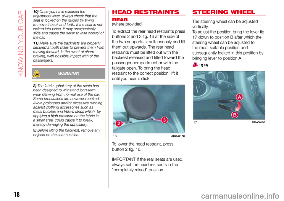
To extract the rear head restraints press
buttons 2 and 3 fig. 16 at the side of
the two supports simultaneously and lift
them out upwards. The rear head
restraints must be lifted out with the
backrest released and tilted toward the
passenger compartment or with the
tailgate open. To bring the head
restraint to the correct position, lift it
until you hear it click.
To lower the head restraint, press
button 2 fig. 16.
IMPORTANT If the rear seats are used,
always set the head restraints in the
"completely raised" position.
STEERING WHEEL
The steering wheel can be adjusted
vertically.
To adjust the position bring the lever fig.
17 down to position B after which the
steering wheel can be adjusted to
the most suitable position and
subsequently locked in this position by
bringing lever to position A.
12) 13)
16AB0A0017C
17AB0A0018C
18
KNOWING YOUR CAR
Page 23 of 192
Theorwarning light will blink on
the instrument panel. The direction
indicators are switched off automatically
when the steering wheel is
straightened.
"FOLLOW ME HOME"
DEVICE
This allows the space in front of the
vehicle to be lit for a set time.
Activation
With the ignition key in the STOP
position or extracted, pull the lever
towards the steering wheel and move it
within 2 minutes of the engine switching
off.
At each single movement of the stalk,
the lights will remain on for an extra
30 seconds up to a maximum of 210
seconds: then the lights are switched
off automatically. The display shows the
time for which the functions remains
active.
The
warning light on the
instrument panel switches on when the
stalk is pulled for the first time and
stays lit until the function switches off
automatically.Deactivation
This function is deactivated turning on
again the headlights, sidelights or
pulling the left lever towards the
steering wheel (unstable position) for
more than 2 seconds, or switching the
starter to MAR.
FRONT FOG
LIGHTS/REAR FOG
LIGHTS
(where provided)
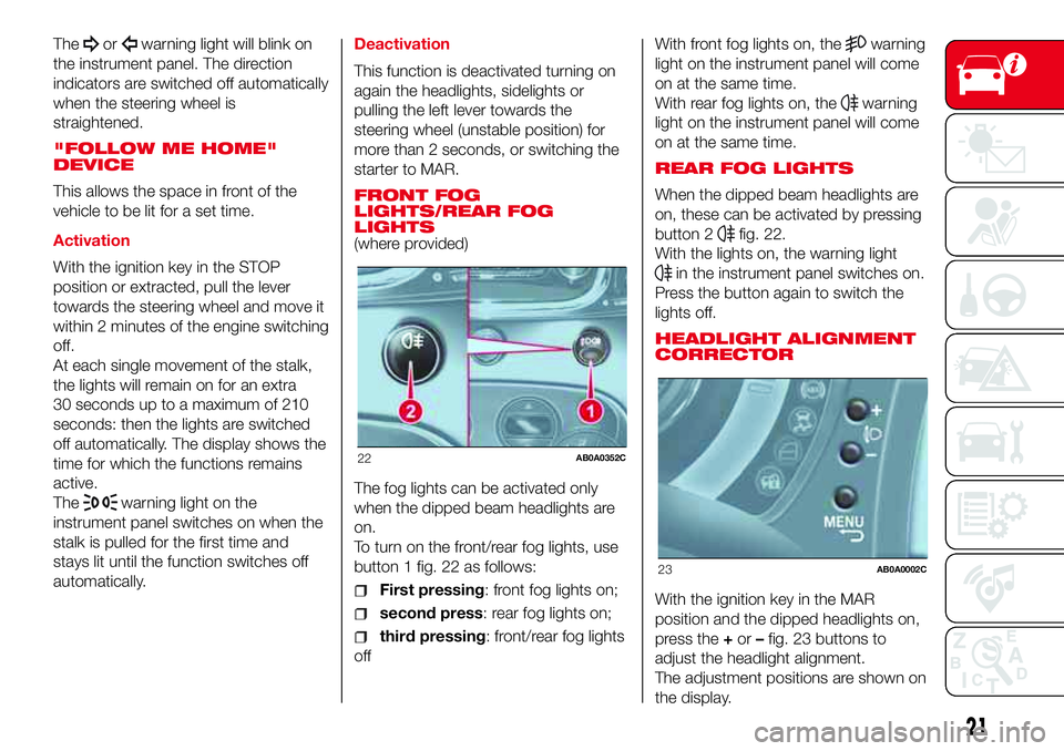
The fog lights can be activated only
when the dipped beam headlights are
on.
To turn on the front/rear fog lights, use
button 1 fig. 22 as follows:
First pressing: front fog lights on;
second press: rear fog lights on;
third pressing: front/rear fog lights
offWith front fog lights on, the
warning
light on the instrument panel will come
on at the same time.
With rear fog lights on, the
warning
light on the instrument panel will come
on at the same time.
REAR FOG LIGHTS
When the dipped beam headlights are
on, these can be activated by pressing
button 2
fig. 22.
With the lights on, the warning light
in the instrument panel switches on.
Press the button again to switch the
lights off.
HEADLIGHT ALIGNMENT
CORRECTOR
With the ignition key in the MAR
position and the dipped headlights on,
press the+or–fig. 23 buttons to
adjust the headlight alignment.
The adjustment positions are shown on
the display.
22AB0A0352C
23AB0A0002C
21
Page 24 of 192
Position 0 - one or two people in the
front seats.
Position1-4passengers.
Position2-4passengers + load in the
luggage compartment.
Position 3 - driver + maximum
permitted load stowed in the luggage
compartment.
IMPORTANT Gas discharge headlights
(Xenon headlights) are automatically
adjusted. Headlight alignment
adjustment is electronic and therefore
cannot be manually adjusted using
the+and–buttons.
WARNING
16)The daytime running lights are an
alternative to the dipped headlights for
driving during the daytime in countries
where it is compulsory to have lights on
during the day; where it is not compulsory,
the use of daytime running lights is
permitted.
17)Daytime running lights cannot replace
dipped beam headlights when driving at
night or through tunnels. The use of
daytime running lights is governed by the
highway code of the country in which
you are driving. Comply with legal
requirements.
ROOF LIGHTS
FRONT CEILING LIGHT
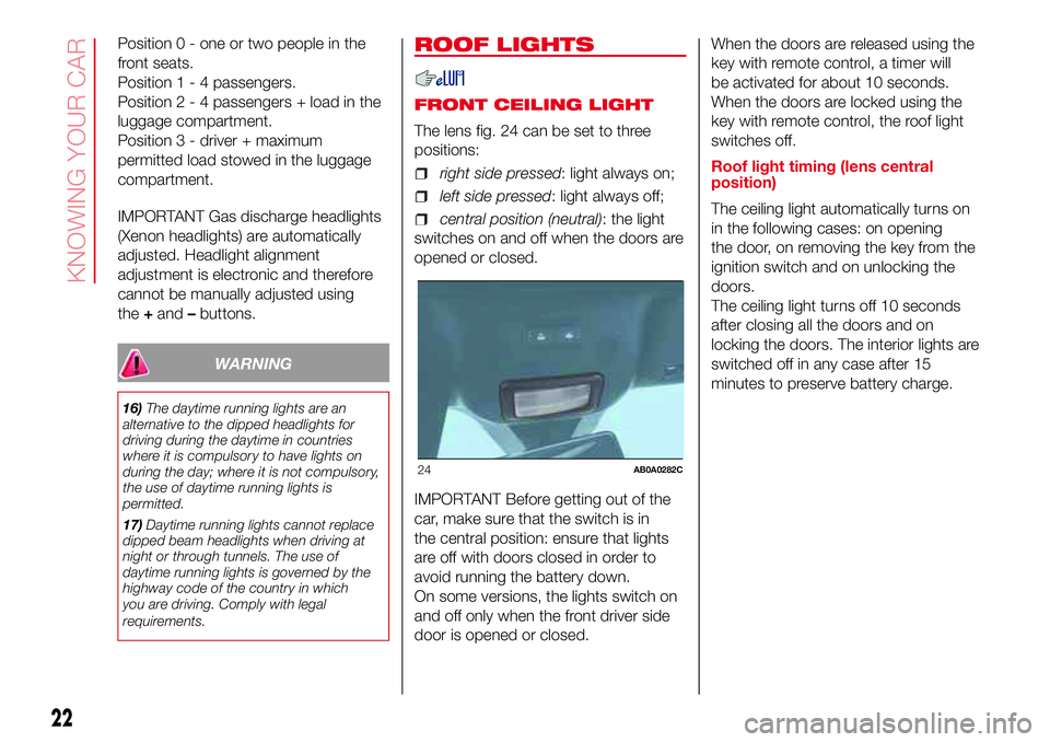
The lens fig. 24 can be set to three
positions:
right side pressed: light always on;
left side pressed: light always off;
central position (neutral): the light
switches on and off when the doors are
opened or closed.
IMPORTANT Before getting out of the
car, make sure that the switch is in
the central position: ensure that lights
are off with doors closed in order to
avoid running the battery down.
On some versions, the lights switch on
and off only when the front driver side
door is opened or closed.When the doors are released using the
key with remote control, a timer will
be activated for about 10 seconds.
When the doors are locked using the
key with remote control, the roof light
switches off.
Roof light timing (lens central
position)
The ceiling light automatically turns on
in the following cases: on opening
the door, on removing the key from the
ignition switch and on unlocking the
doors.
The ceiling light turns off 10 seconds
after closing all the doors and on
locking the doors. The interior lights are
switched off in any case after 15
minutes to preserve battery charge.
24AB0A0282C
22
KNOWING YOUR CAR
Page 30 of 192
3)
Depending on the temperature set by
the user, the automatic climate control
system automatically regulates the
temperature, flow and distribution of the
passenger compartment air, as well as
the recirculation function. These
settings can be changed by the user,
putting the climate control system
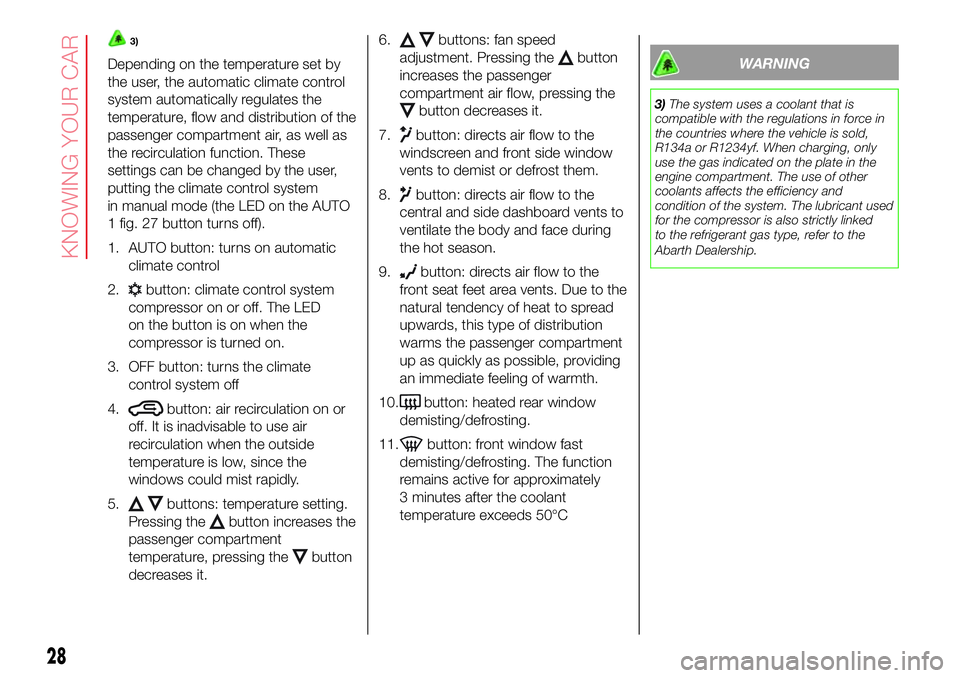
in manual mode (the LED on the AUTO
1 fig. 27 button turns off).
1. AUTO button: turns on automatic
climate control
2.
button: climate control system
compressor on or off. The LED
on the button is on when the
compressor is turned on.
3. OFF button: turns the climate
control system off
4.
button: air recirculation on or
off. It is inadvisable to use air
recirculation when the outside
temperature is low, since the
windows could mist rapidly.
5.
buttons: temperature setting.
Pressing the
button increases the
passenger compartment
temperature, pressing the
button
decreases it.6.
buttons: fan speed
adjustment. Pressing the
button
increases the passenger
compartment air flow, pressing the
button decreases it.
7.
button: directs air flow to the
windscreen and front side window
vents to demist or defrost them.
8.
button: directs air flow to the
central and side dashboard vents to
ventilate the body and face during
the hot season.
9.
button: directs air flow to the
front seat feet area vents. Due to the
natural tendency of heat to spread
upwards, this type of distribution
warms the passenger compartment
up as quickly as possible, providing
an immediate feeling of warmth.
10.
button: heated rear window
demisting/defrosting.
11.
button: front window fast
demisting/defrosting. The function
remains active for approximately
3 minutes after the coolant
temperature exceeds 50°C
WARNING
3)The system uses a coolant that is
compatible with the regulations in force in
the countries where the vehicle is sold,
R134a or R1234yf. When charging, only
use the gas indicated on the plate in the
engine compartment. The use of other
coolants affects the efficiency and
condition of the system. The lubricant used
for the compressor is also strictly linked
to the refrigerant gas type, refer to the
Abarth Dealership.
28
KNOWING YOUR CAR
Page 31 of 192
ELECTRIC WINDOWS
19) 20)
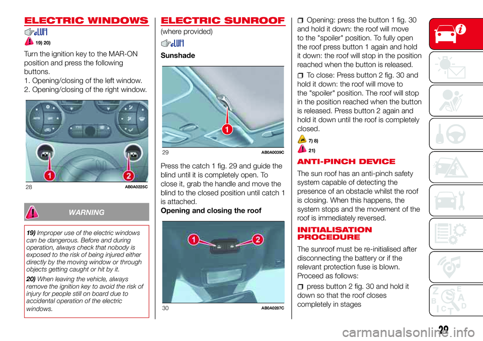
Turn the ignition key to the MAR-ON
position and press the following
buttons.
1. Opening/closing of the left window.
2. Opening/closing of the right window.
WARNING
19)Improper use of the electric windows
can be dangerous. Before and during
operation, always check that nobody is
exposed to the risk of being injured either
directly by the moving window or through
objects getting caught or hit by it.
20)When leaving the vehicle, always
remove the ignition key to avoid the risk of
injury for people still on board due to
accidental operation of the electric
windows.
ELECTRIC SUNROOF
(where provided)
Sunshade
Press the catch 1 fig. 29 and guide the
blind until it is completely open. To
close it, grab the handle and move the
blind to the closed position until catch 1
is attached.
Opening and closing the roof
Opening: press the button 1 fig. 30
and hold it down: the roof will move
to the "spoiler" position. To fully open
the roof press button 1 again and hold
it down: the roof will stop in the position
reached when the button is released.
To close: Press button 2 fig. 30 and
hold it down: the roof will move to
the "spoiler" position. The roof will stop
in the position reached when the button
is released. Press button 2 again and
hold it down until the roof is completely
closed.
7) 8)
21)
ANTI-PINCH DEVICE
The sun roof has an anti-pinch safety
system capable of detecting the
presence of an obstacle whilst the roof
is closing. When this happens, the
system stops and the movement of the
roof is immediately reversed.
INITIALISATION
PROCEDURE
The sunroof must be re-initialised after
disconnecting the battery or if the
relevant protection fuse is blown.
Proceed as follows:
press button 2 fig. 30 and hold it
down so that the roof closes
completely in stages
28AB0A0225C
1
29AB0A0039C
30AB0A0287C
29
Page 32 of 192
after full closing, wait for the sun roof
motor to stop.
EMERGENCY OPERATION
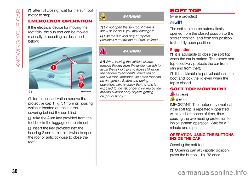
If the electrical device for moving the
roof fails, the sun roof can be moved
manually proceeding as described
below:
for manual activation remove the
protective cap 1 fig. 31 from its housing
which is located on the internal
covering behind the sun blind
take the Allen key provided from the
tool box in the luggage compartment
insert the key provided into the
housing 2 and turn it clockwise to open
the roof or anticlockwise to close the
roof.
WARNING
7)Do not open the sun roof if there is
snow or ice on it: you may damage it
8)Use the sun roof only at "spoiler"
position if a transverse roof rack is fitted.
WARNING
21)When leaving the vehicle, always
remove the key from the ignition switch to
avoid the risk of injury to those still inside
the car due to accidental operation of
the sun roof. Improper use of the roof can
be dangerous. Before and during
operation, always check that no-one is
exposed to the risk of being injured by the
moving sunroof or by objects getting
caught or hit by it.
SOFT TOP
(where provided)
The soft top can be automatically
opened from the closed position to the
spoiler position, and from this position
to the fully open position.
Suggestions
it is advisable to close the soft top
when the car is parked. The closed soft
top effectively protects the car from
rain and from theft;
it is advisable to put valuables in the
boot and lock the lid even when the
top is closed.
SOFT TOP MOVEMENT
22) 23) 24)
9) 10) 11)
IMPORTANT: The motor may overheat
if the soft top is repeatedly operated
within a short space of time, thus
causing the overheating protection to
inhibit system operation. Wait for a
minute and repeat.
OPERATION USING THE BUTTONS
INSIDE THE CAR
Opening the soft top:
Opening partially (spoiler position):
press the button 1 fig. 32 once .
2
1
31AB0A0040C
30
KNOWING YOUR CAR
Page 33 of 192
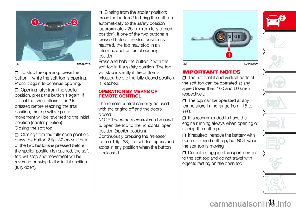
To stop the opening: press the
button 1 while the soft top is opening.
Press it again to continue opening.
Opening fully: from the spoiler
position, press the button 1 again. If
one of the two buttons 1 or 2 is
pressed before reaching the final
position, the top will stop and
movement will be reversed to the initial
position (spoiler position).
Closing the soft top:
Closing from the fully open position:
press the button 2 fig. 32 once. If one
of the two buttons is pressed before
the spoiler position is reached, the soft
top will stop and movement will be
reversed, moving to the initial position
(fully open).
Closing from the spoiler position:
press the button 2 to bring the soft top
automatically to the safety position
(approximately 25 cm from fully closed
position). If one of the two buttons is
pressed before the stop position is
reached, the top may stop in an
intermediate horizontal opening
position.
Press and hold the button 2 with the
soft top in the safety position. The top
will stop instantly if the button is
released before the fully closed position
is reached.
OPERATION BY MEANS OF
REMOTE CONTROL
The remote control can only be used
with the engine off and the doors
closed.
NOTE The remote control can be used
to open the top to the horizontal open
position (spoiler position).
Continuously pressing the "release"
button 1 fig. 33, the soft top opens and
stops in any position when the button
is released.IMPORTANT NOTES
The horizontal and vertical parts of
the soft top can be operated at any
speed lower than 100 and 80 km/h
respectively.
The top can be operated at any
temperature in the range from -18 to
+80.
It is recommended to have the
engine running always when opening or
closing the soft top.
If required, remove the battery with
open or closed soft top, but NOT when
the soft top is moving.
Do not fix luggage transport devices
to the soft top and do not travel with
objects resting on the open top.
32AB0A0287C
1
33AB0A0332C
31
Page 43 of 192
GEAR SHIFT INDICATOR
The GSI (Gear Shift Indicator) system
advises the driver to change gear
through a special indication on the
display.
Through the GSI, the driver is informed
that the gear change will allow a
reduction in fuel consumption.
When the SHIFT (SHIFT UP) icon
is
shown on the display, the GSI is
advising the driver to engage a higher
gear, while the SHIFT (SHIFT DOWN)
icon
advises the driver to engage
a lower gear.
The indication on the instrument panel
remains until the driver shifts gear or the
driving conditions return to a situation
where gearshifting is not required to
improve consumption.
ANALOGUE PRESSURE
GAUGE
The car is equipped with a pressure
gauge for measuring the turbocharger
pressure by means of the analogue
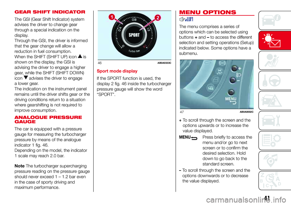
indicator 1 fig. 46.
Depending on the model, the indicator
1 scale may reach 2.0 bar.
NoteThe turbocharger supercharging
pressure reading on the pressure gauge
should never exceed 1 – 1.2 bar even
in the case of sporty driving and
maximum performance.Sport mode display
If the SPORT function is used, the
display 2 fig. 46 inside the turbocharger
pressure gauge will show the word
“SPORT”.
MENU OPTIONS
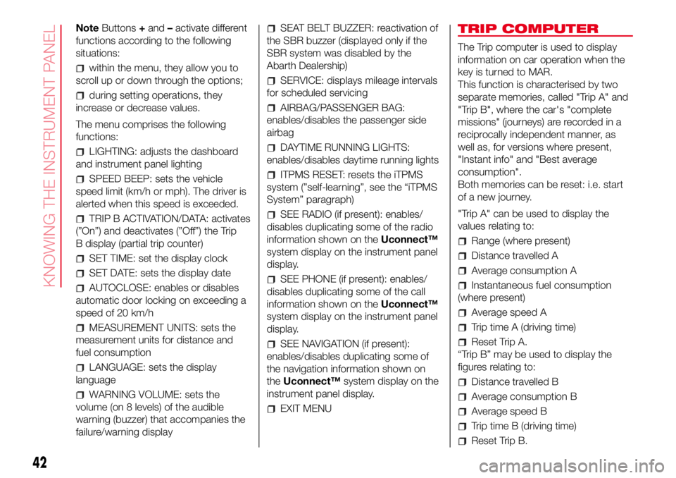
The menu comprises a series of
options which can be selected using
buttons+and–to access the different
selection and setting operations (Setup)
indicated below. Some options have a
submenu.
+To scroll through the screen and the
options upwards or to increase the
value displayed.
MENUPress briefly to access the
menu and/or go to next
screen or to confirm the
desired selection. Hold
down to go back to the
standard screen.
–To scroll through the screen and the
options downwards or to decrease
the value displayed.
46AB0A0333C
47AB0A0002C
41
Page 44 of 192
NoteButtons+and–activate different
functions according to the following
situations:
within the menu, they allow you to
scroll up or down through the options;
during setting operations, they
increase or decrease values.
The menu comprises the following
functions:
LIGHTING: adjusts the dashboard
and instrument panel lighting
SPEED BEEP: sets the vehicle
speed limit (km/h or mph). The driver is
alerted when this speed is exceeded.
TRIP B ACTIVATION/DATA: activates
(”On”) and deactivates (”Off”) the Trip
B display (partial trip counter)
SET TIME: set the display clock
SET DATE: sets the display date
AUTOCLOSE: enables or disables
automatic door locking on exceeding a
speed of 20 km/h
MEASUREMENT UNITS: sets the
measurement units for distance and
fuel consumption
LANGUAGE: sets the display
language
WARNING VOLUME: sets the
volume (on 8 levels) of the audible
warning (buzzer) that accompanies the
failure/warning display
SEAT BELT BUZZER: reactivation of
the SBR buzzer (displayed only if the
SBR system was disabled by the
Abarth Dealership)
SERVICE: displays mileage intervals
for scheduled servicing
AIRBAG/PASSENGER BAG:
enables/disables the passenger side
airbag
DAYTIME RUNNING LIGHTS:
enables/disables daytime running lights
ITPMS RESET: resets the iTPMS
system (”self-learning”, see the “iTPMS
System” paragraph)
SEE RADIO (if present): enables/
disables duplicating some of the radio
information shown on theUconnect™
system display on the instrument panel
display.
SEE PHONE (if present): enables/
disables duplicating some of the call
information shown on theUconnect™
system display on the instrument panel
display.
SEE NAVIGATION (if present):
enables/disables duplicating some of
the navigation information shown on
theUconnect™system display on the
instrument panel display.
EXIT MENU
TRIP COMPUTER
The Trip computer is used to display
information on car operation when the
key is turned to MAR.
This function is characterised by two
separate memories, called "Trip A" and
"Trip B", where the car's "complete
missions" (journeys) are recorded in a
reciprocally independent manner, as
well as, for versions where present,
"Instant info" and "Best average
consumption".
Both memories can be reset: i.e. start
of a new journey.
"Trip A" can be used to display the
values relating to:
Range (where present)
Distance travelled A
Average consumption A
Instantaneous fuel consumption
(where present)
Average speed A
Trip time A (driving time)
Reset Trip A.
“Trip B” may be used to display the
figures relating to:
Distance travelled B
Average consumption B
Average speed B
Trip time B (driving time)
Reset Trip B.
42
KNOWING THE INSTRUMENT PANEL