instrument panel Abarth 500 2020 Owner handbook (in English)
[x] Cancel search | Manufacturer: ABARTH, Model Year: 2020, Model line: 500, Model: Abarth 500 2020Pages: 196, PDF Size: 3.53 MB
Page 9 of 196
KNOWING YOUR CAR
KNOWING THE INSTRUMENT PANEL
SAFETY
STARTING AND DRIVING
IN AN EMERGENCY
SERVICING AND CARE
TECHNICAL DATA
MULTIMEDIA
INDEX
7
Page 11 of 196
KNOWING YOUR CAR
In-depth knowledge of your new vehicle
starts here.
The handbook that you are reading
simply and directly explains how it
is made and how it works.
That’s why we advise you to read it
seated comfortably on board, so that
you can see what is described here for
yourself.INSTRUMENT PANEL ..................... 10
KEYS .............................................. 11
IGNITION DEVICE ........................... 12
FIAT CODE SYSTEM ....................... 13
DOORS ........................................... 14
SEATS ............................................ 15
HEADRESTS ................................... 18
STEERING WHEEL ......................... 19
REAR VIEW MIRRORS .................... 19
EXTERIOR LIGHTS ......................... 20
ROOF LIGHTS ................................ 23
WINDOW WASHING ....................... 24
MANUAL CLIMATE CONTROL
SYSTEM ......................................... 27
AUTOMATIC CLIMATE CONTROL
SYSTEM ......................................... 29
WINDOW WINDERS ....................... 31
ELECTRIC SUNROOF ..................... 31
SOFT TOP ...................................... 33
ENGINE BONNET ........................... 37
LUGGAGE COMPARTMENT ........... 38
9
Page 12 of 196
INSTRUMENT PANEL
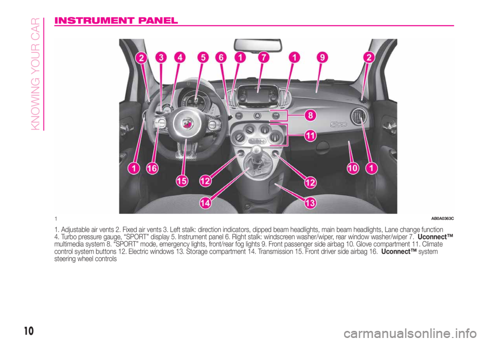
1. Adjustable air vents 2. Fixed air vents 3. Left stalk: direction indicators, dipped beam headlights, main beam headlights, Lane change function
4. Turbo pressure gauge, “SPORT” display 5. Instrument panel 6. Right stalk: windscreen washer/wiper, rear window washer/wiper 7.Uconnect™
multimedia system 8. “SPORT” mode, emergency lights, front/rear fog lights 9. Front passenger side airbag 10. Glove compartment 11. Climate
control system buttons 12. Electric windows 13. Storage compartment 14. Transmission 15. Front driver side airbag 16.Uconnect™system
steering wheel controls
1AB0A0363C
10
KNOWING YOUR CAR
Page 23 of 196
DIPPED HEADLIGHTS/
SIDE LIGHTS
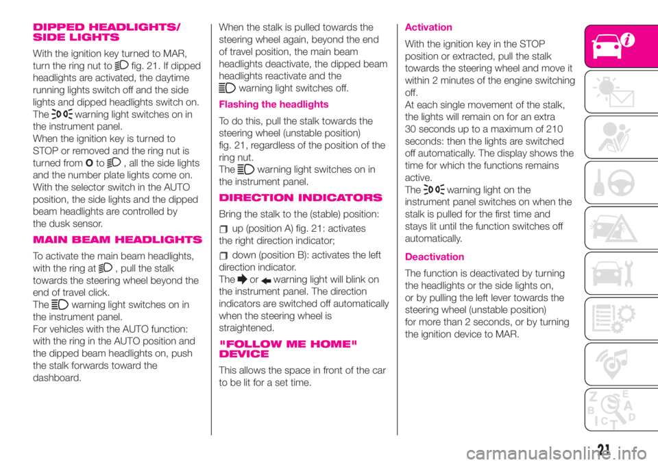
With the ignition key turned to MAR,
turn the ring nut to
fig. 21. If dipped
headlights are activated, the daytime
running lights switch off and the side
lights and dipped headlights switch on.
The
warning light switches on in
the instrument panel.
When the ignition key is turned to
STOP or removed and the ring nut is
turned fromOto
, all the side lights
and the number plate lights come on.
With the selector switch in the AUTO
position, the side lights and the dipped
beam headlights are controlled by
the dusk sensor.
MAIN BEAM HEADLIGHTS
To activate the main beam headlights,
with the ring at
, pull the stalk
towards the steering wheel beyond the
end of travel click.
The
warning light switches on in
the instrument panel.
For vehicles with the AUTO function:
with the ring in the AUTO position and
the dipped beam headlights on, push
the stalk forwards toward the
dashboard.When the stalk is pulled towards the
steering wheel again, beyond the end
of travel position, the main beam
headlights deactivate, the dipped beam
headlights reactivate and the
warning light switches off.
Flashing the headlights
To do this, pull the stalk towards the
steering wheel (unstable position)
fig. 21, regardless of the position of the
ring nut.
The
warning light switches on in
the instrument panel.
DIRECTION INDICATORS
Bring the stalk to the (stable) position:
up (position A) fig. 21: activates
the right direction indicator;
down (position B): activates the left
direction indicator.
The
orwarning light will blink on
the instrument panel. The direction
indicators are switched off automatically
when the steering wheel is
straightened.
"FOLLOW ME HOME"
DEVICE
This allows the space in front of the car
to be lit for a set time.
Activation
With the ignition key in the STOP
position or extracted, pull the stalk
towards the steering wheel and move it
within 2 minutes of the engine switching
off.
At each single movement of the stalk,
the lights will remain on for an extra
30 seconds up to a maximum of 210
seconds: then the lights are switched
off automatically. The display shows the
time for which the functions remains
active.
The
warning light on the
instrument panel switches on when the
stalk is pulled for the first time and
stays lit until the function switches off
automatically.
Deactivation
The function is deactivated by turning
the headlights or the side lights on,
or by pulling the left lever towards the
steering wheel (unstable position)
for more than 2 seconds, or by turning
the ignition device to MAR.
21
Page 24 of 196
AUTO FUNCTION
(for versions/markets, where provided)
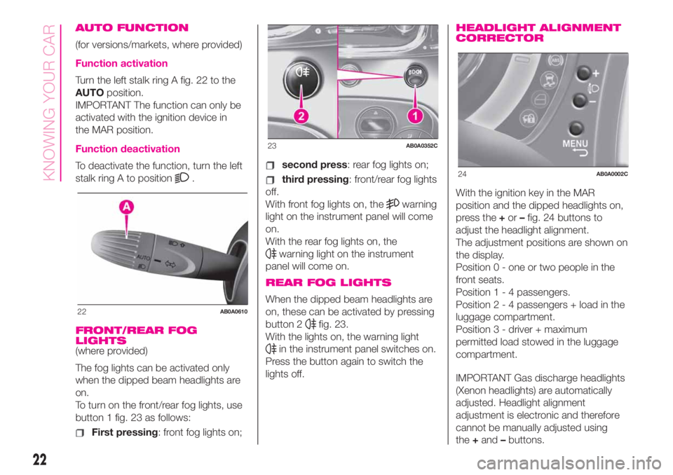
Function activation
Turn the left stalk ring A fig. 22 to the
AUTOposition.
IMPORTANT The function can only be
activated with the ignition device in
the MAR position.
Function deactivation
To deactivate the function, turn the left
stalk ring A to position
.
FRONT/REAR FOG
LIGHTS
(where provided)
The fog lights can be activated only
when the dipped beam headlights are
on.
To turn on the front/rear fog lights, use
button 1 fig. 23 as follows:
First pressing: front fog lights on;
second press: rear fog lights on;
third pressing: front/rear fog lights
off.
With front fog lights on, the
warning
light on the instrument panel will come
on.
With the rear fog lights on, the
warning light on the instrument
panel will come on.
REAR FOG LIGHTS
When the dipped beam headlights are
on, these can be activated by pressing
button 2
fig. 23.
With the lights on, the warning light
in the instrument panel switches on.
Press the button again to switch the
lights off.
HEADLIGHT ALIGNMENT
CORRECTOR
With the ignition key in the MAR
position and the dipped headlights on,
press the+or–fig. 24 buttons to
adjust the headlight alignment.
The adjustment positions are shown on
the display.
Position 0 - one or two people in the
front seats.
Position1-4passengers.
Position2-4passengers + load in the
luggage compartment.
Position 3 - driver + maximum
permitted load stowed in the luggage
compartment.
IMPORTANT Gas discharge headlights
(Xenon headlights) are automatically
adjusted. Headlight alignment
adjustment is electronic and therefore
cannot be manually adjusted using
the+and–buttons.
22AB0A0610
23AB0A0352C
24AB0A0002C
22
KNOWING YOUR CAR
Page 42 of 196
KNOWING THE INSTRUMENT PANEL
This section of the handbook gives you
all the information you need to
understand, interpret and use the
instrument panel correctly.CONTROL PANEL AND
ON-BOARD INSTRUMENTS ........... 41
MENU OPTIONS ............................. 43
TRIP COMPUTER ........................... 44
WARNING LIGHTS AND
MESSAGES .................................... 47
-SEAT BELTS REMINDER.................... 47
-EBD FAILURE .................................... 48
-AIR BAG FAILURE .............................. 48
-LOW BRAKE FLUID/HANDBRAKE
ENGAGED........................................... 49
-“DUALDRIVE” ELECTRIC POWER
STEERING FAILURE ............................ 49
-BRAKE PAD WEAR ............................ 50
-ESC SYSTEM .................................... 50
-INJECTION / EOBD SYSTEM
FAILURE .............................................. 51
-REAR FOG LIGHT .............................. 51
-ABS FAILURE..................................... 51
-iTPMS ................................................ 52
-SIDE LIGHTS AND DIPPED BEAM
HEADLIGHTS/FOLLOW ME HOME ..... 52
-FOG LIGHTS ...................................... 53
-LEFT DIRECTION INDICATOR ............ 53
-RIGHT DIRECTION INDICATOR ......... 53
-MAIN BEAM HEADLIGHTS ................ 53
-DOORS/BONNET/LUGGAGE
COMPARTMENT OPEN ...................... 54
-LOW BATTERY CHARGE ................... 54
-INSUFFICIENT ENGINE OIL
PRESSURE/ENGINE OIL
DETERIORATED .................................. 54
-ENGINE COOLANT TEMPERATURE
TOO HIGH........................................... 55
-ROBOTISED SEQUENTIAL
GEARBOX FAILURE ............................ 55
-SPEED LIMIT EXCEEDED .................. 55-POSSIBLE ICE ON ROAD .................. 56
-PARKING SENSOR FAILURE ............. 56
-SERVICE (SCHEDULED SERVICING)
EXPIRED ............................................. 56
-ASR SYSTEM .................................... 56
-HILL HOLDER FAILURE ..................... 56
-FUEL CUT-OFF SYSTEM.................... 56
-FUEL CUT-OFF SYSTEM FAILURE ..... 57
-EXTERIOR LIGHTS FAILURE .............. 57
-BRAKE LIGHT FAILURE ..................... 57
-FIAT CODE SYSTEM FAILURE ........... 57
-FUEL RESERVE - LIMITED RANGE .... 58
-ENGINE OIL PRESSURE SENSOR
FAILURE INDICATOR........................... 58
-OIL CHANGE ..................................... 58
-PRESS THE CLUTCH PEDAL TO
START ................................................. 58
-FUEL LEVEL SENSOR FAILURE......... 58
-RAIN SENSOR FAILURE .................... 58
-DUSK SENSOR FAILURE ................... 58
-HEADLIGHT ALIGNMENT
CORRECTOR ...................................... 59
40
KNOWING THE INSTRUMENT PANEL
Page 43 of 196
CONTROL PANEL AND ON-BOARD INSTRUMENTS
.
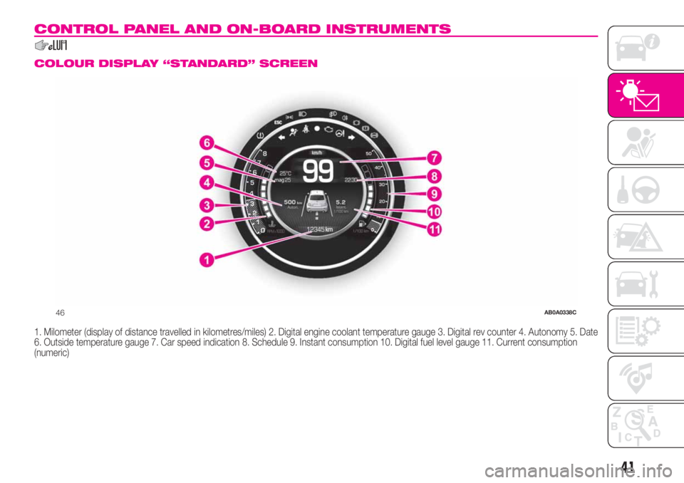
COLOUR DISPLAY “STANDARD” SCREEN
1. Milometer (display of distance travelled in kilometres/miles) 2. Digital engine coolant temperature gauge 3. Digital rev counter 4. Autonomy 5. Date
6. Outside temperature gauge 7. Car speed indication 8. Schedule 9. Instant consumption 10. Digital fuel level gauge 11. Current consumption
(numeric)
46AB0A0338C
41
Page 44 of 196
SPORT MODE
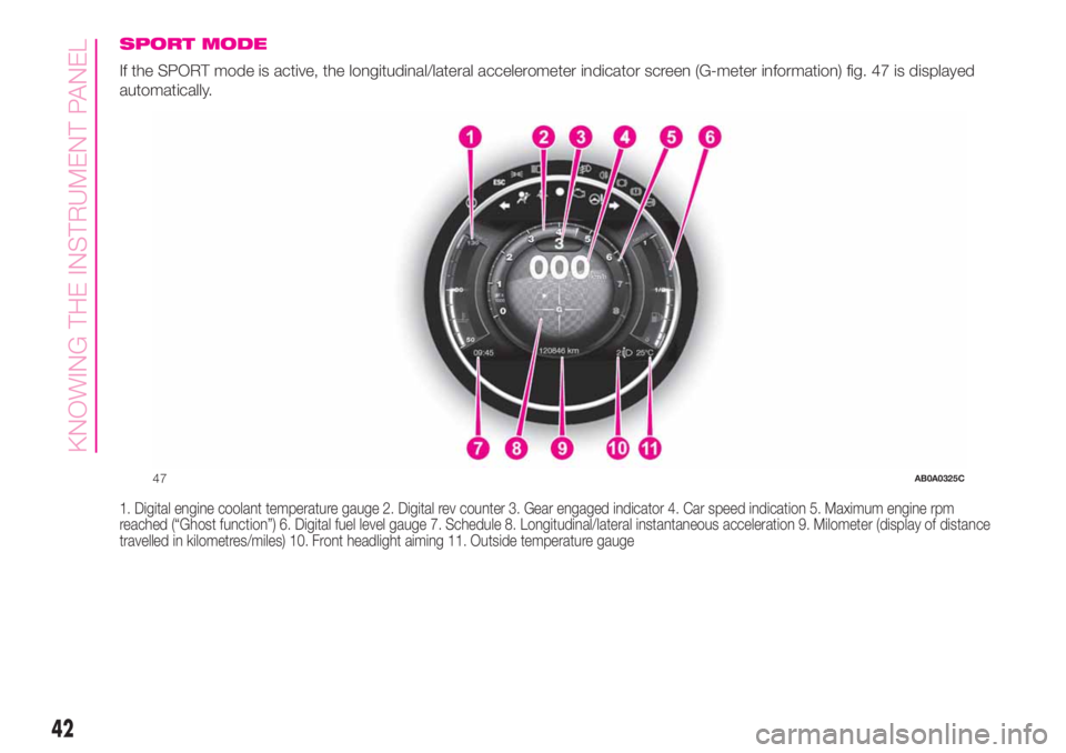
If the SPORT mode is active, the longitudinal/lateral accelerometer indicator screen (G-meter information) fig. 47 is displayed
automatically.
1. Digital engine coolant temperature gauge 2. Digital rev counter 3. Gear engaged indicator 4. Car speed indication 5. Maximum engine rpm
reached (“Ghost function”) 6. Digital fuel level gauge 7. Schedule 8. Longitudinal/lateral instantaneous acceleration 9. Milometer (display of distance
travelled in kilometres/miles) 10. Front headlight aiming 11. Outside temperature gauge
47AB0A0325C
42
KNOWING THE INSTRUMENT PANEL
Page 45 of 196
GEAR SHIFT INDICATOR
The GSI (Gear Shift Indicator) system
advises the driver to change gear
through a special indication on the
display.
Through the GSI, the driver is informed
that the gear change will allow a
reduction in fuel consumption.
When the SHIFT (SHIFT UP) icon
is
shown on the display, the GSI is
advising the driver to engage a higher
gear, while the SHIFT (SHIFT DOWN)
icon
advises the driver to engage
a lower gear.
The indication on the instrument panel
remains until the driver shifts gear or the
driving conditions return to a situation
where gearshifting is not required to
improve consumption.
ANALOGUE PRESSURE
GAUGE
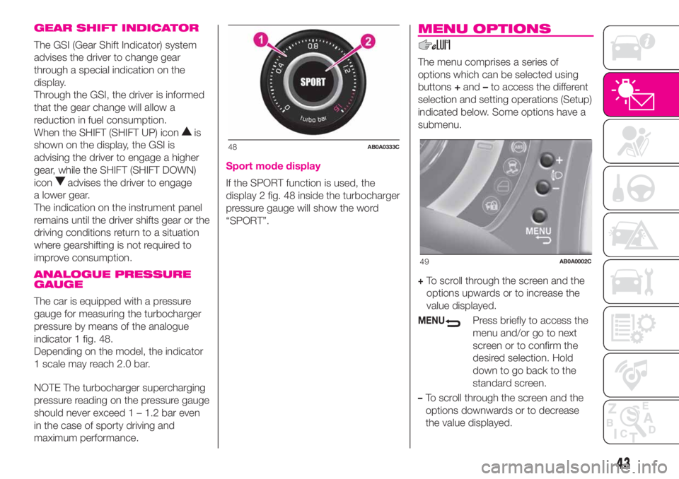
The car is equipped with a pressure
gauge for measuring the turbocharger
pressure by means of the analogue
indicator 1 fig. 48.
Depending on the model, the indicator
1 scale may reach 2.0 bar.
NOTE The turbocharger supercharging
pressure reading on the pressure gauge
should never exceed 1 – 1.2 bar even
in the case of sporty driving and
maximum performance.
Sport mode display
If the SPORT function is used, the
display 2 fig. 48 inside the turbocharger
pressure gauge will show the word
“SPORT”.
MENU OPTIONS
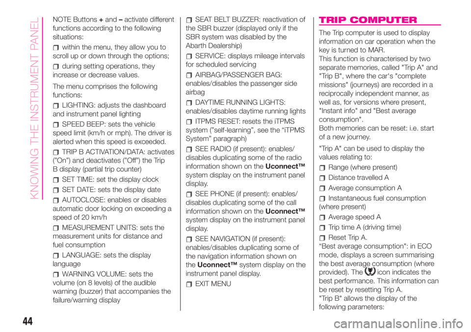
The menu comprises a series of
options which can be selected using
buttons+and–to access the different
selection and setting operations (Setup)
indicated below. Some options have a
submenu.
+To scroll through the screen and the
options upwards or to increase the
value displayed.
MENUPress briefly to access the
menu and/or go to next
screen or to confirm the
desired selection. Hold
down to go back to the
standard screen.
–To scroll through the screen and the
options downwards or to decrease
the value displayed.
48AB0A0333C
49AB0A0002C
43
Page 46 of 196
NOTE Buttons+and–activate different
functions according to the following
situations:
within the menu, they allow you to
scroll up or down through the options;
during setting operations, they
increase or decrease values.
The menu comprises the following
functions:
LIGHTING: adjusts the dashboard
and instrument panel lighting
SPEED BEEP: sets the vehicle
speed limit (km/h or mph). The driver is
alerted when this speed is exceeded.
TRIP B ACTIVATION/DATA: activates
(”On”) and deactivates (”Off”) the Trip
B display (partial trip counter)
SET TIME: set the display clock
SET DATE: sets the display date
AUTOCLOSE: enables or disables
automatic door locking on exceeding a
speed of 20 km/h
MEASUREMENT UNITS: sets the
measurement units for distance and
fuel consumption
LANGUAGE: sets the display
language
WARNING VOLUME: sets the
volume (on 8 levels) of the audible
warning (buzzer) that accompanies the
failure/warning display
SEAT BELT BUZZER: reactivation of
the SBR buzzer (displayed only if the
SBR system was disabled by the
Abarth Dealership)
SERVICE: displays mileage intervals
for scheduled servicing
AIRBAG/PASSENGER BAG:
enables/disables the passenger side
airbag
DAYTIME RUNNING LIGHTS:
enables/disables daytime running lights
ITPMS RESET: resets the iTPMS
system (”self-learning”, see the “iTPMS
System” paragraph)
SEE RADIO (if present): enables/
disables duplicating some of the radio
information shown on theUconnect™
system display on the instrument panel
display.
SEE PHONE (if present): enables/
disables duplicating some of the call
information shown on theUconnect™
system display on the instrument panel
display.
SEE NAVIGATION (if present):
enables/disables duplicating some of
the navigation information shown on
theUconnect™system display on the
instrument panel display.
EXIT MENU
TRIP COMPUTER
The Trip computer is used to display
information on car operation when the
key is turned to MAR.
This function is characterised by two
separate memories, called "Trip A" and
"Trip B", where the car's "complete
missions" (journeys) are recorded in a
reciprocally independent manner, as
well as, for versions where present,
"Instant info" and "Best average
consumption".
Both memories can be reset: i.e. start
of a new journey.
"Trip A" can be used to display the
values relating to:
Range (where present)
Distance travelled A
Average consumption A
Instantaneous fuel consumption
(where present)
Average speed A
Trip time A (driving time)
Reset Trip A.
“Best average consumption": in ECO
mode, displays a screen summarising
the best average consumption (where
provided). The
icon indicates the
best performance. This information can
be reset by resetting Trip A.
"Trip B" allows the display of the
following parameters:
44
KNOWING THE INSTRUMENT PANEL