technical specifications Abarth Grande Punto 2010 Owner handbook (in English)
[x] Cancel search | Manufacturer: ABARTH, Model Year: 2010, Model line: Grande Punto, Model: Abarth Grande Punto 2010Pages: 207, PDF Size: 3.01 MB
Page 136 of 207

134
WARNING
LIGHTS AND
MESSAGES
CAR
MAINTENANCE
TECHNICAL
SPECIFICATIONS
IINDEX
DASHBOARD
AND CONTROLS
SAFETY
DEVICES
CORRECT USE
OF THE CAR
IN AN
EMERGENCY
ENGINE
STARTING
EMERGENCY START-UP
If the
Ysign keeps being displayed, im-
mediately call the Abarth Dealership.
JUMP STARTING fig. 1
If the battery is flat, it is possible to start
the engine using an auxiliary battery with
the same capacity or a little higher than
the flat one. Proceed as follows:
❒connect positive terminals (+near the
terminal) of the two batteries with a
jump lead;
❒with a second lead, connect the nega-
tive terminal (–) of the auxiliary battery
to an earthing point
Eon the engine or
the gearbox of the car to be started;
❒ start the engine;
❒when the engine has been started, re-
move the leads reversing the order
above.
If after a few attempts the engine does not
start, do not insist but contact the near-
est Abarth Dealership.
IMPORTANT Do not directly connect the
negative terminals of the two batteries:
sparks could ignite the flammable gas from
the battery. If the other battery is fitted in
another car, prevent accidental contacts
between the metal parts of the two cars.BUMP STARTING
Never bump start the engine (by pushing,
towing, or coasting downhill) as this could
cause fuel to flow into the catalytic ex-
haust system and damage it beyond repair.
IMPORTANT Remember that the brake
booster and the power steering system
are not operating until the engine is start-
ed, a greater effort will therefore be re-
quired to press the brake pedal or turn
the steering wheel.
The starting procedure must
be carried out by qualified
personnel because incorrect opera-
tions may cause electrical discharge of
considerable intensity. The liquid con-
tained in the battery is poisonous and
corrosive. Avoid contact with the skin
and eyes. Keep naked flames and light-
ed cigarettes away from the battery
and do not cause sparks.
WARNING
fig. 1F0M104Ab
Page 137 of 207
135
WARNING
LIGHTS AND
MESSAGES
CAR
MAINTENANCE
TECHNICAL
SPECIFICATIONS
INDEX
DASHBOARD
AND CONTROLS
SAFETY
DEVICES
CORRECT USE
OF THE CAR
IN AN
EMERGENCY
QUICK TYRE REPAIR
KIT - FIX & GO
automatic
The quick tyre repair kit Fix & Go auto-
matic is placed in the boot.
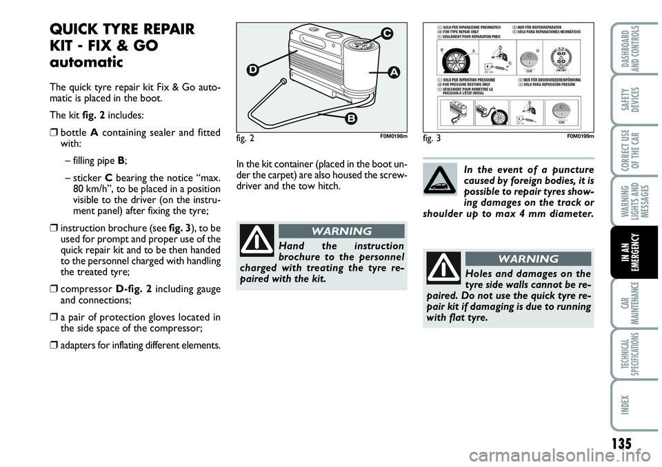
The kit fig. 2includes:
❒bottle A containing sealer and fitted
with:
– filling pipe B;
– sticker Cbearing the notice “max.
80 km/h”, to be placed in a position
visible to the driver (on the instru-
ment panel) after fixing the tyre;
❒instruction brochure (see fig. 3), to be
used for prompt and proper use of the
quick repair kit and to be then handed
to the personnel charged with handling
the treated tyre;
❒compressor D-fig. 2including gauge
and connections;
❒a pair of protection gloves located in
the side space of the compressor;
❒adapters for inflating different elements.In the kit container (placed in the boot un-
der the carpet) are also housed the screw-
driver and the tow hitch.
Hand the instruction
brochure to the personnel
charged with treating the tyre re-
paired with the kit.
WARNING
fig. 2F0M0198mfig. 3F0M0199m
In the event of a puncture
caused by foreign bodies, it is
possible to repair tyres show-
ing damages on the track or
shoulder up to max 4 mm diameter.
Holes and damages on the
tyre side walls cannot be re-
paired. Do not use the quick tyre re-
pair kit if damaging is due to running
with flat tyre.
WARNING
Page 138 of 207
136
WARNING
LIGHTS AND
MESSAGES
CAR
MAINTENANCE
TECHNICAL
SPECIFICATIONS
IINDEX
DASHBOARD
AND CONTROLS
SAFETY
DEVICES
CORRECT USE
OF THE CAR
IN AN
EMERGENCY
IT SHOULD BE NOTICED THAT:
The sealing fluid of the quick tyre repair
kit is effective with external temperatures
between –20 °C and +50 °C.
The sealing fluid has limited life. INFLATING PROCEDURE
The compressor shall not be
operated for more than 20
minutes. Risk of overheating. Tyres
repaired with the quick tyre repair kit
shall be used temporarily only.
WARNING
The cylinder contains ethyl-
ene glycol. The cylinder con-
tains latex: it can cause allergic reac-
tions. It is harmful if ingested or in-
haled and irritant for the eyes and in
case of contact. In case of contact
rinse immediately with water and take
off contaminated clothes. If swal-
lowed, do not induce vomit, rinse out
the mouth, drink a lot of water and
call the doctor immediately. Keep
away from children. This product must
not be used by asthmatics. Do not in-
hale vapours. Call the doctor imme-
diately in case of allergic reactions.
Keep the cylinder in the space provid-
ed for the purpose and far from heat.
The sealing fluid has limited life.
WARNING
Replace the cylinder if sealer
has run out. Do not throw
away the cylinder and the
sealing fluid. Have the sealing
fluid and the cylinder disposed of in
compliance with national and local
regulations.
Put on the protection gloves
provided together with quick
tyre repair kit.
WARNING
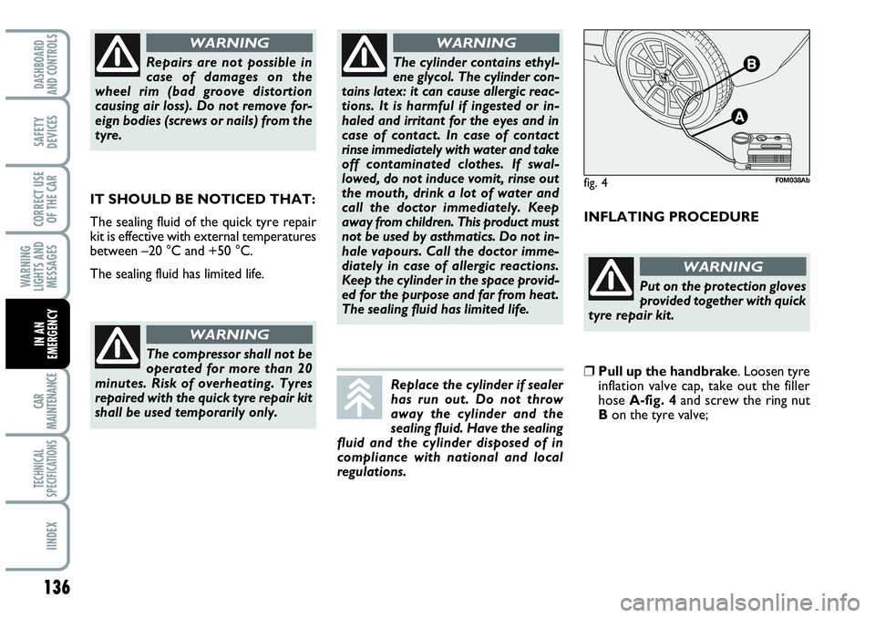
❒Pull up the handbrake. Loosen tyre
inflation valve cap, take out the filler
hose A-fig. 4and screw the ring nut
Bon the tyre valve;
Repairs are not possible in
case of damages on the
wheel rim (bad groove distortion
causing air loss). Do not remove for-
eign bodies (screws or nails) from the
tyre.
WARNING
fig. 4F0M038Ab
Page 139 of 207
137
WARNING
LIGHTS AND
MESSAGES
CAR
MAINTENANCE
TECHNICAL
SPECIFICATIONS
INDEX
DASHBOARD
AND CONTROLS
SAFETY
DEVICES
CORRECT USE
OF THE CAR
IN AN
EMERGENCY
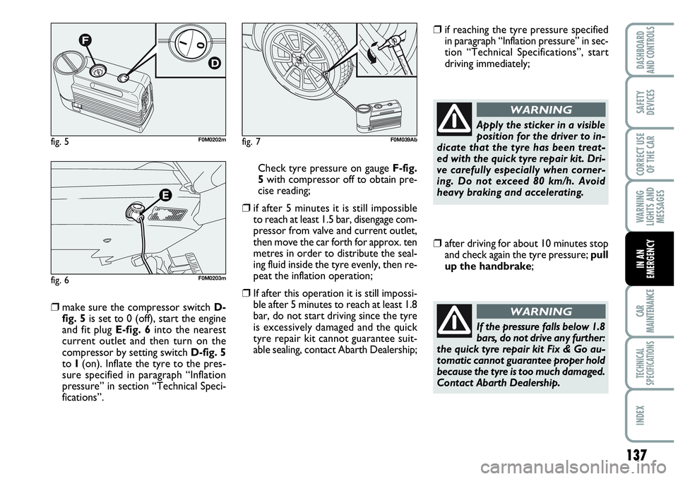
❒make sure the compressor switch D-
fig. 5is set to 0 (off), start the engine
and fit plug E-fig. 6into the nearest
current outlet and then turn on the
compressor by setting switch D-fig. 5
to I(on). Inflate the tyre to the pres-
sure specified in paragraph “Inflation
pressure” in section “Technical Speci-
fications”. Check tyre pressure on gauge F-fig.
5 with compressor off to obtain pre-
cise reading;
❒if after 5 minutes it is still impossible
to reach at least 1.5 bar, disengage com-
pressor from valve and current outlet,
then move the car forth for approx. ten
metres in order to distribute the seal-
ing fluid inside the tyre evenly, then re-
peat the inflation operation;
❒If after this operation it is still impossi-
ble after 5 minutes to reach at least 1.8
bar, do not start driving since the tyre
is excessively damaged and the quick
tyre repair kit cannot guarantee suit-
able sealing, contact Abarth Dealership;
❒if reaching the tyre pressure specified
in paragraph “Inflation pressure” in sec-
tion “Technical Specifications”, start
driving immediately;
Apply the sticker in a visible
position for the driver to in-
dicate that the tyre has been treat-
ed with the quick tyre repair kit. Dri-
ve carefully especially when corner-
ing. Do not exceed 80 km/h. Avoid
heavy braking and accelerating.
WARNING
❒after driving for about 10 minutes stop
and check again the tyre pressure; pull
up the handbrake;
If the pressure falls below 1.8
bars, do not drive any further:
the quick tyre repair kit Fix & Go au-
tomatic cannot guarantee proper hold
because the tyre is too much damaged.
Contact Abarth Dealership.
WARNING
fig. 5F0M0202m
fig. 6F0M0203m
fig. 7F0M039Ab
Page 140 of 207

138
WARNING
LIGHTS AND
MESSAGES
CAR
MAINTENANCE
TECHNICAL
SPECIFICATIONS
IINDEX
DASHBOARD
AND CONTROLS
SAFETY
DEVICES
CORRECT USE
OF THE CAR
IN AN
EMERGENCY
❒if at least 1.8 bar pressure is read, re-
store proper pressure (with engine
running and handbrake on) and restart;
❒drive with the utmost care to the near-
est Abarth Dealership.
FOR CHECKING AND
RESTORING PRESSURE ONLY
The compressor can be also used just for
restoring pressure. Disconnect the quick
connection and connect it directly to the
tyre valve fig. 8; in this way the cylinder is
not connected to compressor and the
sealing fluid will not flow into the tyre. CYLINDER REPLACEMENT
PROCEDURE
To replace the cylinder proceed as fol-
lows:
❒disconnect connection A-fig. 9;
❒turn counter-clockwise the cylinder to
replace and raise it;
❒fit the new cylinder and turn it clock-
wise;
❒connect connection Ato the cylinder
and fit the transparent tube Binto the
proper space.
It is of vital importance to
communicate that the tyre
has been repaired using the quick tyre
repair kit. Hand the instruction
brochure to the personnel charged
with treating the tyre repaired with
the kit.
WARNING
fig. 8F0M040Abfig. 9F0M0206m
Page 141 of 207
139
WARNING
LIGHTS AND
MESSAGES
CAR
MAINTENANCE
TECHNICAL
SPECIFICATIONS
INDEX
DASHBOARD
AND CONTROLS
SAFETY
DEVICES
CORRECT USE
OF THE CAR
IN AN
EMERGENCY
WHEN NEEDING TO
CHANGE A BULB
GENERAL INSTRUCTIONS
❒ When a light is not working, check that
the corresponding fuse is intact before
changing a bulb. For the location of fus-
es, refer to the paragraph “If a fuse
blows” in this section;
❒ Before changing a bulb check the con-
tacts for oxidation;
❒ Burnt bulbs must be replaced by oth-
ers of the same type and power;
❒ Always check the height of the head-
light beam after changing a bulb.
IMPORTANT The headlight inner surface
may be lightly misted over: this is not a
fault but a natural fact due to low tem-
perature and the level of air humidity. It
will disappear as soon the headlights are
turned on. The presence of drops inside
the headlights means water infiltration,
therefore contact Abarth Dealership.
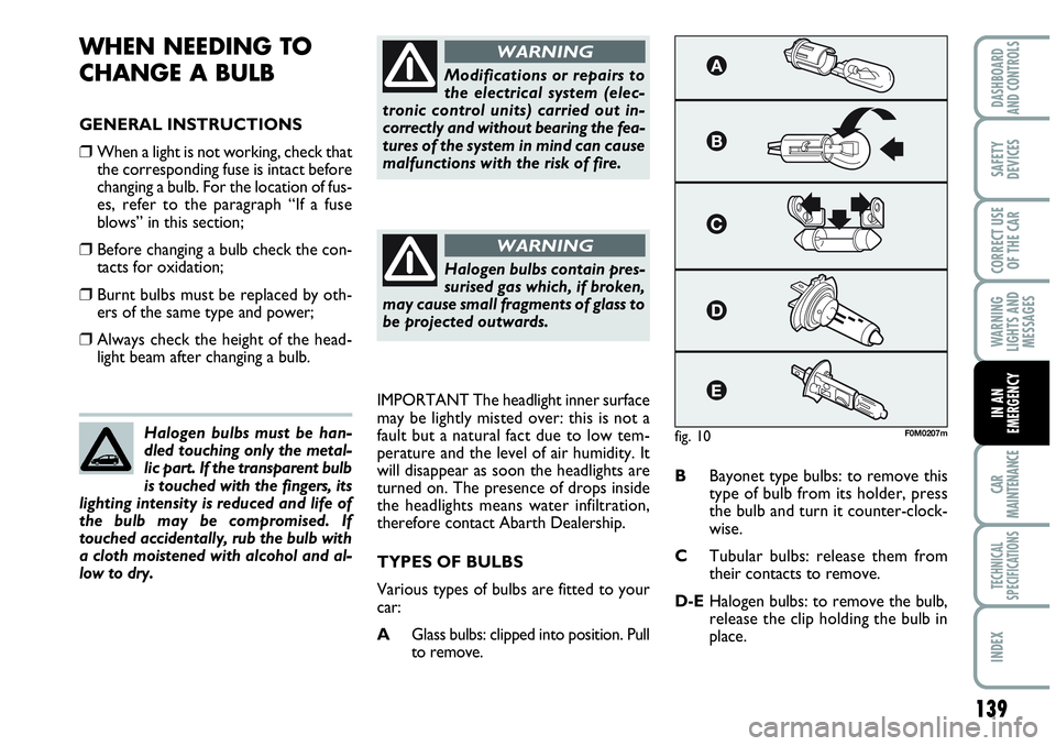
TYPES OF BULBS
Various types of bulbs are fitted to your
car:
AGlass bulbs: clipped into position. Pull
to remove.BBayonet type bulbs: to remove this
type of bulb from its holder, press
the bulb and turn it counter-clock-
wise.
CTubular bulbs: release them from
their contacts to remove.
D-EHalogen bulbs: to remove the bulb,
release the clip holding the bulb in
place. Halogen bulbs must be han-
dled touching only the metal-
lic part. If the transparent bulb
is touched with the fingers, its
lighting intensity is reduced and life of
the bulb may be compromised. If
touched accidentally, rub the bulb with
a cloth moistened with alcohol and al-
low to dry.
Modifications or repairs to
the electrical system (elec-
tronic control units) carried out in-
correctly and without bearing the fea-
tures of the system in mind can cause
malfunctions with the risk of fire.
WARNING
Halogen bulbs contain pres-
surised gas which, if broken,
may cause small fragments of glass to
be projected outwards.
WARNING
fig. 10F0M0207m
Page 142 of 207
140
WARNING
LIGHTS AND
MESSAGES
CAR
MAINTENANCE
TECHNICAL
SPECIFICATIONS
IINDEX
DASHBOARD
AND CONTROLS
SAFETY
DEVICES
CORRECT USE
OF THE CAR
IN AN
EMERGENCY
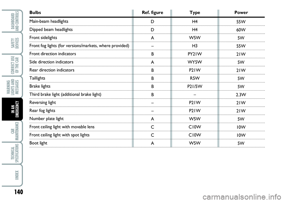
Bulbs Ref. figure Type Power
Main-beam headlights
Dipped beam headlights
Front sidelights
Front fog lights (for versions/markets, where provided)
Front direction indicators
Side direction indicators
Rear direction indicators
Taillights
Brake lights
Third brake light (additional brake light)
Reversing light
Rear fog lights
Number plate light
Front ceiling light with movable lens
Front ceiling light with spot lights
Boot light H4
H4
W5W
H3
PY21W
WY5W
P21W
R5W
P21/5W
–
P21W
P21W
W5W
C10W
C10W
W5W D
D
A
–
B
A
B
B
B
B
–
–
A
C
C
A55W
60W
5W
55W
21W
5W
21W
5W
5W
2.3W
21W
21W
5W
10W
10W
5W
Page 143 of 207
141
WARNING
LIGHTS AND
MESSAGES
CAR
MAINTENANCE
TECHNICAL
SPECIFICATIONS
INDEX
DASHBOARD
AND CONTROLS
SAFETY
DEVICES
CORRECT USE
OF THE CAR
IN AN
EMERGENCY
IF AN EXTERIOR LIGHT
BURNS OUT
For the type of bulb and power rating, see
“When needing to change a bulb”.
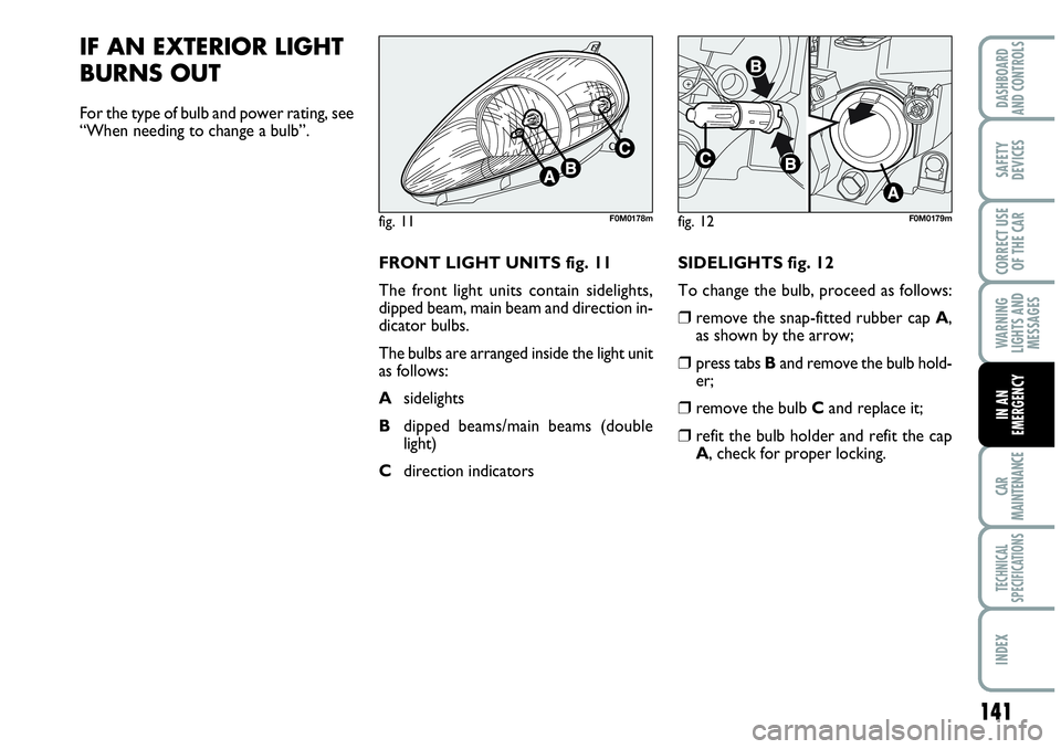
FRONT LIGHT UNITS fig. 11
The front light units contain sidelights,
dipped beam, main beam and direction in-
dicator bulbs.
The bulbs are arranged inside the light unit
as follows:
Asidelights
Bdipped beams/main beams (double
light)
Cdirection indicatorsSIDELIGHTS fig. 12
To change the bulb, proceed as follows:
❒remove the snap-fitted rubber cap A,
as shown by the arrow;
❒press tabs Band remove the bulb hold-
er;
❒remove the bulb Cand replace it;
❒refit the bulb holder and refit the cap
A, check for proper locking.
fig. 11F0M0178mfig. 12F0M0179m
Page 144 of 207
142
WARNING
LIGHTS AND
MESSAGES
CAR
MAINTENANCE
TECHNICAL
SPECIFICATIONS
IINDEX
DASHBOARD
AND CONTROLS
SAFETY
DEVICES
CORRECT USE
OF THE CAR
IN AN
EMERGENCY
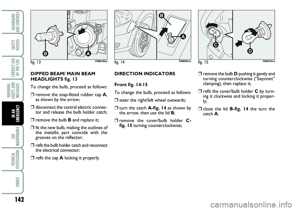
DIPPED BEAM/ MAIN BEAM
HEADLIGHTS fig. 13
To change the bulb, proceed as follows:
❒remove the snap-fitted rubber cap A,
as shown by the arrow;
❒disconnect the central electric connec-
tor and release the bulb holder catch;
❒remove the bulb Band replace it;
❒fit the new bulb, making the outlines of
the metallic part coincide with the
grooves on the reflector;
❒refit the bulb holder catch and reconnect
the electrical connector;
❒refit the cap Alocking it properly.DIRECTION INDICATORS
Front fig. 14-15
To change the bulb, proceed as follows:
❒steer the right/left wheel outwards;
❒turn the catch A-fig. 14as shown by
the arrow, then use the lid B;
❒remove the cover/bulb holder C-
fig. 15turning counterclockwise;
❒remove the bulb Dpushing it gently and
turning counterclockwise (“bayonet”
clamping), then replace it;
❒refit the cover/bulb holder Cby turn-
ing it clockwise and locking it proper-
ly;
❒close the lid B-fig. 14the turn the
catch A.
fig. 13F0M0180mfig. 14F0M0261mfig. 15F0M0181m
Page 145 of 207

143
WARNING
LIGHTS AND
MESSAGES
CAR
MAINTENANCE
TECHNICAL
SPECIFICATIONS
INDEX
DASHBOARD
AND CONTROLS
SAFETY
DEVICES
CORRECT USE
OF THE CAR
IN AN
EMERGENCY
Side fig. 16
To change the bulb, proceed as follows:
❒work on the lens Ato compress the in-
ternal catch B, then pull the unit out-
wards;
❒turn the bulb holder C counterclock-
wise, remove the snap-fitted bulb D
and replace it;
❒refit the bulb holder Cin the lens by
turning it clockwise;
❒refit the unit making sure the catch
clicks into place B.FRONT FOG LIGHTS
(where provided)
Contact Abarth Dealership to have front
fog lights A-fig. 17replaced.
REAR LIGHT UNITS fig. 18-19
Rear light units contain taillights, brake
light and direction indicators bulbs.
The bulbs are arranged inside the light unit
as follows:
Bdirection indicators
Ctaillights
Dtaillights/brake light (double light).
fig. 16F0M0182m
fig. 18F0M0184m
fig. 17F0M041Ab