technical specifications Abarth Grande Punto 2010 Owner handbook (in English)
[x] Cancel search | Manufacturer: ABARTH, Model Year: 2010, Model line: Grande Punto, Model: Abarth Grande Punto 2010Pages: 207, PDF Size: 3.01 MB
Page 146 of 207

144
WARNING
LIGHTS AND
MESSAGES
CAR
MAINTENANCE
TECHNICAL
SPECIFICATIONS
IINDEX
DASHBOARD
AND CONTROLS
SAFETY
DEVICES
CORRECT USE
OF THE CAR
IN AN
EMERGENCY
To change the bulb proceed as follows:
❒open the tailgate then, slacken the two
fastening screws A;
❒disconnect the central electric connec-
tor and pull the lens unit outwards;
❒slacken the screws Eand remove the
bulb holder;
❒remove the bulb to replace B, Cor D
pushing it slightly and turning it coun-
terclockwise (“bayonet” clamping) and
replace it;
❒refit the bulb holder and tighten the
screws E;
❒reconnect the electric connector, suit-
ably refit the unit to the car body and
then tighten the fastening screws A.
fig. 20F0M0208m
fig. 19F0M0185m
REAR FOG LIGHTS fig. 20
Contact Abarth Dealership to have rear
fog lights Areplaced.
Page 147 of 207

145
WARNING
LIGHTS AND
MESSAGES
CAR
MAINTENANCE
TECHNICAL
SPECIFICATIONS
INDEX
DASHBOARD
AND CONTROLS
SAFETY
DEVICES
CORRECT USE
OF THE CAR
IN AN
EMERGENCY
REVERSING LIGHT fig. 21
Contact Abarth Dealership to have re-
versing light Areplaced.THIRD BRAKE LIGHT fig. 22-23
To change the bulb proceed as follows:
❒open the tailgate;
❒remove the rubber caps A-fig. 22;
❒press the catches B-fig. 22and remove
the lens unit C-fig. 23;
❒disconnect the electric connector;
❒press the tabs D-fig. 23and remove
the bulb holder;
❒remove the snap-fitted bulb and re-
place it.NUMBER PLATE LIGHT fig. 24-25
To change the bulb proceed as follows:
❒work in the point shown by the arrow
and remove lens A-fig. 24;
fig. 21F0M0209mfig. 22F0M0210mfig. 23F0M0211m
fig. 24F0M0212m
Page 148 of 207

146
WARNING
LIGHTS AND
MESSAGES
CAR
MAINTENANCE
TECHNICAL
SPECIFICATIONS
IINDEX
DASHBOARD
AND CONTROLS
SAFETY
DEVICES
CORRECT USE
OF THE CAR
IN AN
EMERGENCY
IF AN INTERIOR LIGHT
BURNS OUT
For the type of bulb and power rating, see
“When needing to change a bulb”.
FRONT CEILING LIGHT
To replace the bulbs proceed as follows:
❒work in the points shown by the ar-
rows and remove light A-fig. 26
❒open the protection lid B;❒change the bulb fig. 25releasing it from
the side contacts and making sure the
new bulb is correctly fastened between
the contacts;
❒refit the snap-fitted lens unit.
fig. 26F0M0213m
fig. 27F0M0234m
fig. 25F0M0233m
❒replace bulbs C-fig. 27releasing them
from the side contacts; make sure that
new bulbs are correctly clamped be-
tween contacts;
❒re-close the lid B-fig. 27and secure light
A-fig. 26into its housing locking it
properly.
Page 149 of 207

147
WARNING
LIGHTS AND
MESSAGES
CAR
MAINTENANCE
TECHNICAL
SPECIFICATIONS
INDEX
DASHBOARD
AND CONTROLS
SAFETY
DEVICES
CORRECT USE
OF THE CAR
IN AN
EMERGENCY
BOOT LIGHT fig. 28
To change the bulb, proceed as follows:
❒ open the tailgate;
❒remove the light Alevering in the point
shown by the arrow;
❒open the protection Band replace the
snap-fitted bulb;
❒re-close the protective cover Bon the
lens;
❒refit the light Ainserting it in its cor-
rect position firstly on one end and
then on the other until it clicks into
place.PUDDLE LIGHTS
(for versions/markets,
where provided) fig. 29-30
To change the bulb, proceed as follows:
❒remove the light by pressing clip Awith
a screwdriver;
❒press the bulb protection cover sides
Bon the two fastening pins and turn it;
❒replace the snap-fitted bulb C;
fig. 28F0M0216mfig. 29F0M0217mfig. 30F0M0229m
❒refit bulb protection cover fitting the
two fastening pins;
❒refit the ceiling light inserting first end
Dand then pressing the other end un-
til hearing the locking click of the clip.
Page 150 of 207

148
WARNING
LIGHTS AND
MESSAGES
CAR
MAINTENANCE
TECHNICAL
SPECIFICATIONS
IINDEX
DASHBOARD
AND CONTROLS
SAFETY
DEVICES
CORRECT USE
OF THE CAR
IN AN
EMERGENCY
IF A FUSE BLOWS
GENERAL
The fuse is a protective device for the
electric system: it comes into action (i.e.
it cuts off) mainly due to a fault or im-
proper action on the system.
When a device does not work, check the
efficiency of its fuse: the conductor ele-
ment A- fig. 31must be intact. If not, re-
place the fuse with one of the same amp
rating (same colour).
Bundamaged fuse fig. 31
Cfuse with damaged filament fig. 31.
fig. 31F0M0236m
Never change a fuse with
another with a higher amp
rating, DANGER OF FIRE.
WARNING
Never replace a broken fuse
with anything other than a
new fuse.
If a general fuse (MEGA-
FUSE, MIDI-FUSE, MAXI-
FUSE) cuts in, do not attempt any re-
pair and contact Abarth Dealership.
WARNING
If a fuse blows again, contact
a Abarth Dealership.
WARNING
Before changing a fuse,
check the ignition key has
been removed and that all the other
electric devices have been turned
off/disabled.
WARNING
Page 151 of 207

149
WARNING
LIGHTS AND
MESSAGES
CAR
MAINTENANCE
TECHNICAL
SPECIFICATIONS
INDEX
DASHBOARD
AND CONTROLS
SAFETY
DEVICES
CORRECT USE
OF THE CAR
IN AN
EMERGENCY
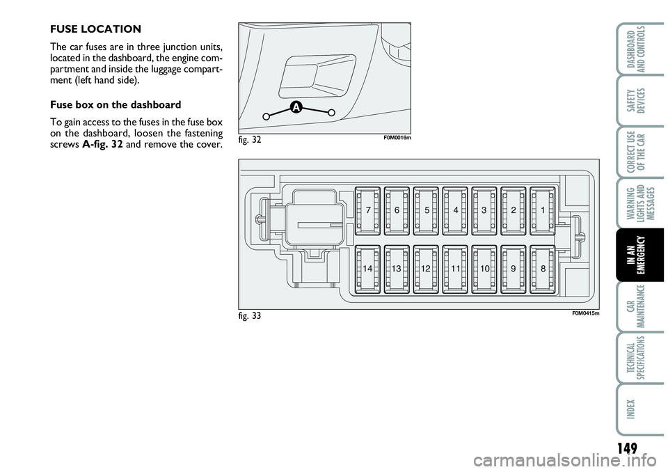
FUSE LOCATION
The car fuses are in three junction units,
located in the dashboard, the engine com-
partment and inside the luggage compart-
ment (left hand side).
Fuse box on the dashboard
To gain access to the fuses in the fuse box
on the dashboard, loosen the fastening
screws A-fig. 32and remove the cover.
fig. 32F0M0016m
fig. 33F0M0415m
3 4 5 6 7
8 9 10 11 12
13 141 2
Page 152 of 207

150
WARNING
LIGHTS AND
MESSAGES
CAR
MAINTENANCE
TECHNICAL
SPECIFICATIONS
IINDEX
DASHBOARD
AND CONTROLS
SAFETY
DEVICES
CORRECT USE
OF THE CAR
IN AN
EMERGENCY
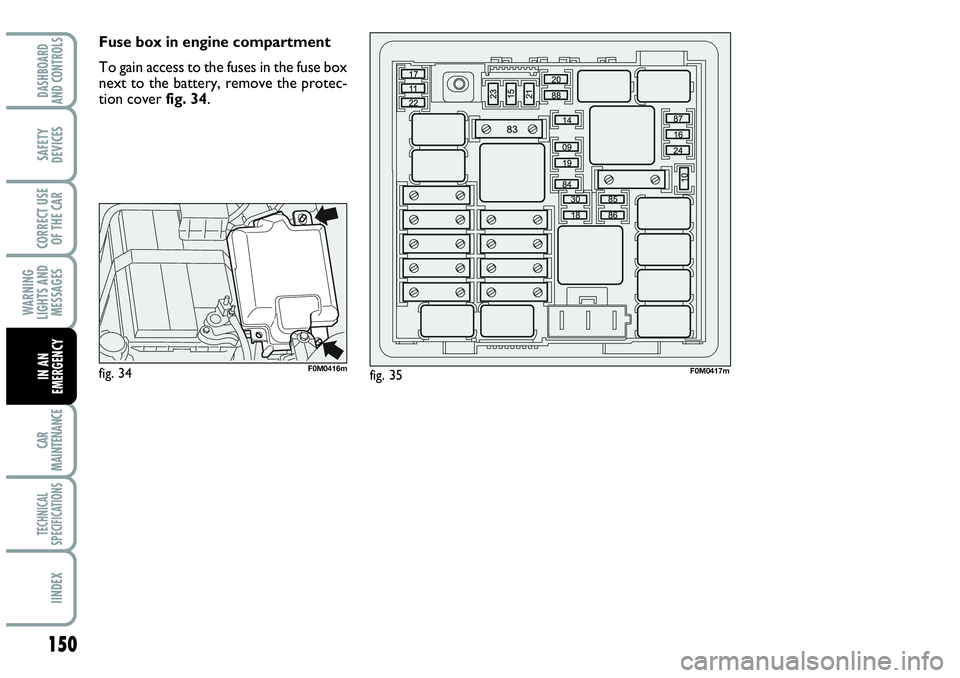
Fuse box in engine compartment
To gain access to the fuses in the fuse box
next to the battery, remove the protec-
tion cover fig. 34.
fig. 34F0M0416mfig. 35F0M0417m
Page 153 of 207

151
WARNING
LIGHTS AND
MESSAGES
CAR
MAINTENANCE
TECHNICAL
SPECIFICATIONS
INDEX
DASHBOARD
AND CONTROLS
SAFETY
DEVICES
CORRECT USE
OF THE CAR
IN AN
EMERGENCY
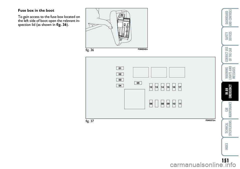
Fuse box in the boot
To gain access to the fuse box located on
the left side of boot open the relevant in-
spection lid (as shown infig. 36).
fig. 37F0M0372m
fig. 36F0M0246m
Page 154 of 207

152
WARNING
LIGHTS AND
MESSAGES
CAR
MAINTENANCE
TECHNICAL
SPECIFICATIONS
IINDEX
DASHBOARD
AND CONTROLS
SAFETY
DEVICES
CORRECT USE
OF THE CAR
IN AN
EMERGENCY
7.5
7.5
5
5
10
5
20
20
20
20 1
8
13
2
5
11
4
6
14
7
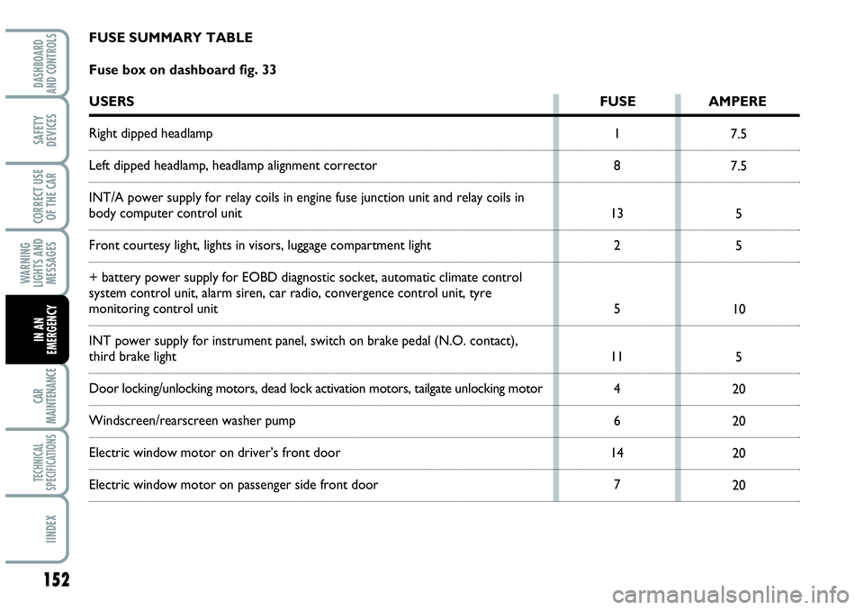
FUSE SUMMARY TABLE
Fuse box on dashboard fig. 33
USERSFUSE AMPERE
Right dipped headlamp
Left dipped headlamp, headlamp alignment corrector
INT/A power supply for relay coils in engine fuse junction unit and relay coils in
body computer control unit
Front courtesy light, lights in visors, luggage compartment light
+ battery power supply for EOBD diagnostic socket, automatic climate control
system control unit, alarm siren, car radio, convergence control unit, tyre
monitoring control unit
INT power supply for instrument panel, switch on brake pedal (N.O. contact),
third brake light
Door locking/unlocking motors, dead lock activation motors, tailgate unlocking motor
Windscreen/rearscreen washer pump
Electric window motor on driver’s front door
Electric window motor on passenger side front door
Page 155 of 207

153
WARNING
LIGHTS AND
MESSAGES
CAR
MAINTENANCE
TECHNICAL
SPECIFICATIONS
INDEX
DASHBOARD
AND CONTROLS
SAFETY
DEVICES
CORRECT USE
OF THE CAR
IN AN
EMERGENCY
5
7.5
5
5 12
9
3
10
USERSFUSE AMPERE
INT power supply for control panel lighting, parking control unit, tyre pressure
monitoring control unit, electric door mirrors movement, rain sensor, electric roof
control unit, by-port infotelematic socket
Air Bag control unit
Instrument panel
INT power supply for switch on brake pedal (NC contact), switch on clutch pedal,
interior heater unit, convergence control unit, car radio preparation system