key Abarth Grande Punto 2010 Owner handbook (in English)
[x] Cancel search | Manufacturer: ABARTH, Model Year: 2010, Model line: Grande Punto, Model: Abarth Grande Punto 2010Pages: 207, PDF Size: 3.01 MB
Page 26 of 207
24
SAFETY
DEVICES
CORRECT USE
OF THE CAR
WARNING
LIGHTS AND
MESSAGES
IN AN
EMERGENCY
CAR
MAINTENANCE
TECHNICAL
SPECIFICATIONS
INDEX
DASHBOARD
AND CONTROLS
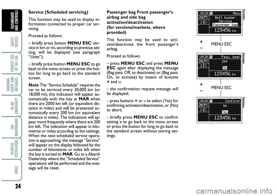
Service (Scheduled servicing)
This function may be used to display in-
formation connected to proper car ser-
vicing.
Proceed as follows:
– briefly press button MENU ESC: ser-
vice in km or mi, according to previous set-
ting, will be displayed (see paragraph
“Units”);
– briefly press button MENU ESCto go
back to the menu screen or press the but-
ton for long to go back to the standard
screen.
NoteThe “Service Schedule” requires the
car to be serviced every 30,000 km (or
18,000 mi); this indication will appear au-
tomatically with the key at MARwhen
there are 2000 km left (or equivalent dis-
tance in miles) and will be presented au-
tomatically every 200 km (or equivalent
distance in miles). The indications will ap-
pear more frequently where there are 200
km left. The indication will appear in kilo-
metres or miles according to the settings.
When the next scheduled service opera-
tion is approaching, the message “Service”
will appear on the display followed by the
number of kilometres or miles left when
the key is turned to MAR. Go to a Abarth
Dealership where the “Scheduled Service”
operations will be performed and the mes-
sage will be reset. Passenger bag Front passenger’s
airbag and side bag
activation/deactivation
(for versions/markets, where
provided)
This function may be used to acti-
vate/deactivate the front passenger’s
airbag.
Proceed as follows:
– press MENU ESCand press MENU
ESCagain after displaying the message
(Bag pass: Off, to deactivate) or (Bag pass:
On, to activate) by means of buttons
+and –;
– the confirmation request message will
be displayed;
– press buttons +or –to select (Yes) for
confirming activation/deactivation, or (No)
to abort;
– briefly press MENU ESCto confirm
setting e to go back to the menu screen
or press the button for long to go back to
the standard screen without storing set-
tings.
MENU ESC
F0M2010g
F0M2008g
F0M2009g
MENU ESC
+
–
+
–
Page 27 of 207

25
SAFETY
DEVICES
CORRECT USE
OF THE CAR
WARNING
LIGHTS AND
MESSAGES
IN AN
EMERGENCY
CAR
MAINTENANCE
TECHNICAL
SPECIFICATIONS
INDEX
DASHBOARD
AND CONTROLS
Exit Menu
This is the last function that closes the cir-
cular setting cycle listed in the initial menu
screen.
Briefly press button MENU ESCto go
back to the standard screen without stor-
ing settings.
Press button –to return to the first menu
option (Speed Beep).TRIP COMPUTER
General features
The “Trip computer” displays information
(with ignition key at MAR), relating to the
operating status of the car. This function
comprises two separate and independent
trips: “Trip A” and “Trip B” concerning
the “complete mission” of the car (jour-
ney).Both functions are resettable (reset - start
of new mission).
“Trip A” shall be used to display the fig-
ures relating to:
– Range
– Trip distance
– Average consumption
– Instant consumption
– Average speed
– Travel time (driving time).
Page 29 of 207
27
SAFETY
DEVICES
CORRECT USE
OF THE CAR
WARNING
LIGHTS AND
MESSAGES
IN AN
EMERGENCY
CAR
MAINTENANCE
TECHNICAL
SPECIFICATIONS
INDEX
DASHBOARD
AND CONTROLS
New mission
Reset can be:
– “manual” resetting by the user, by press-
ing the relevant button;
– “automatic” resetting, when the “Trip dis-
tance” reaches 3999.9 km or 9999.9 km
(according to the type of display) or when
the “Travel time” reaches 99.59 (99 hours
and 59 minutes);
– after disconnecting/reconnecting the
battery.
IMPORTANT The reset operation in the
presence of the screens concerning the
“Trip A” makes it possible to reset only
the information associated with this func-
tion.
IMPORTANT The reset operation in the
presence of the screens concerning the
“Trip B” makes it possible to reset only
the information associated with this func-
tion.Start of journey procedure
With ignition key at MAR, press and keep
button TRIPpressed for over 2 seconds
to reset.
Exit Trip
To quit the Trip function: keep button
MENU ESCpressed for over 2 seconds.
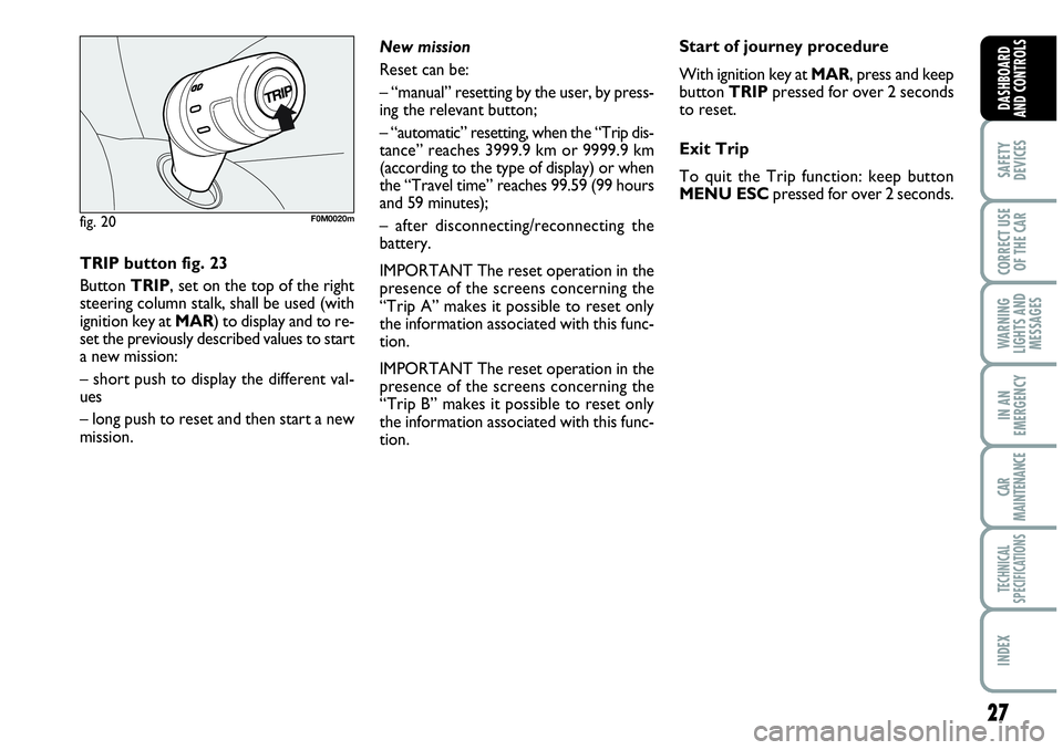
TRIP button fig. 23
Button TRIP, set on the top of the right
steering column stalk, shall be used (with
ignition key at MAR) to display and to re-
set the previously described values to start
a new mission:
– short push to display the different val-
ues
– long push to reset and then start a new
mission.
fig. 20F0M0020m
Page 31 of 207

29
SAFETY
DEVICES
CORRECT USE
OF THE CAR
WARNING
LIGHTS AND
MESSAGES
IIN AN
EMERGENCY
CAR
MAINTENANCE
TECHNICAL
SPECIFICATIONS
INDEX
DASHBOARD
AND CONTROLS
Tilting the back rest fig. 22a
Pull handle Aupwards, the back rest will
tilt and the seat can slide forward by push-
ing the back rest.
Bringing back the back rest the seat will
return to its original position (mechani-
cal memory).
Check that the seat is firm-
ly locked in the runners by
trying to move it back and forth.
WARNING
fig. 22aF0M007Ab
REAR SEATS
To tilt rear seats refer to paragraph
“Extending the boot” in this section.
Upholstery of your car has
been designed to withstand
wear deriving from common
use of the car. You are how-
ever recommended to avoid strong
and/or continuous scratching with
clothing accessories such as metallic
buckles, studs, Velcro fastenings and
the like, since these items cause cir-
cumscribed stress of the cover fabric
that could lead to yarn breaking, and
damage the cover as a consequence.
fig. 22bF0M089Ab
Seat warming (for versions/
markets, where provided) fig. 22b
With ignition key at MAR, press button
Fto switch the seat warming on/off. The
led on the button will light up when the
function is on.
Page 34 of 207

32
SAFETY
DEVICES
CORRECT USE
OF THE CAR
WARNING
LIGHTS AND
MESSAGES
IN AN
EMERGENCY
CAR
MAINTENANCE
TECHNICAL
SPECIFICATIONS
INDEX
DASHBOARD
AND CONTROLS
DOOR MIRRORS
Adjustment fig. 27
This operation is only possible with igni-
tion key at MAR.
Proceed as follows:
❒use switch Bto select the mirror re-
quired (left or right);
❒to adjust the mirror move the switch
Cin the four directions.
It can be moved using the lever Ato two
different positions: normal or antiglare.Folding
When required (for example when the
mirror causes difficulty in narrow spaces)
it is possible to fold the mirror moving it
from position 1-fig. 28to position 2.
When driving the mirrors shall
always be in position 1-fig. 28.
As the driver’s door mirror is
curved, it may slightly alter
the perception of distance.
WARNING
Demisting/defrosting
(for versions/markets,
where provided)
Mirrors are fitted with resistors that will
activate when turning the heated rear win-
dow on (by pressing button
().
IMPORTANT This function is timed and
it will turn off automatically a few minutes
later.
fig. 26F0M0028m
fig. 27F0M0030m
fig. 28F0M0250m
Page 48 of 207

46
SAFETY
DEVICES
CORRECT USE
OF THE CAR
WARNING
LIGHTS AND
MESSAGES
IN AN
EMERGENCY
CAR
MAINTENANCE
TECHNICAL
SPECIFICATIONS
INDEX
DASHBOARD
AND CONTROLS
Heated rear window and door
mirror demisting/defrosting button
(for versions/markets,
where provided) G
Press this button to activate heated rear
window demisting/defrosting.
When this function is on, the button led
is on.
This function is timed and switches off au-
tomatically after about 20 minutes or by
pressing again the button or by turning the
engine off. It will not be switched on au-
tomatically when restarting the engine.
IMPORTANT Do not apply stickers on the
inside of the rear window over the heat-
ing filaments to avoid damage that might
cause it to stop working properly.
Switching the climate control
system off (OFF) E
Press button Eto turn the system off.
When turned off the system conditions
are the following:
❒set temperature displays off;
❒air recirculation is on;
❒conditioner compressor off;
❒fan off.
Heated rear window can be turned on or
off also when the system is off.
IMPORTANT The system will store the
temperatures set before turning off and
will resume them when pressing any but-
ton (except heated rear window); if the
function corresponding to the button
pressed is off it will be turned on; if on it
will be kept active.
Press AUTOto turn the system in au-
tomatic mode.ADDITIONAL HEATER
(for versions/markets,
where provided)
This device shall be used to speed up pas-
senger compartment warming when it is
very cold.
The additional heater turns off automati-
cally after reaching the required comfort
conditions.
Automatic two-zone climate
control system
The additional heater will switch on au-
tomatically after turning the ignition key
to ON.
Manual Heater and Climate
control system
The additional heater will switch on au-
tomatically by turning knob Ato the last
red sector and turning the fan on (knob
B) to the first speed at least.
IMPORTANT Heater works only with
low outside temperature and engine
coolant temperature.
IMPORTANT Heater will not turn on if
the battery voltage is not sufficient.
Page 49 of 207
47
SAFETY
DEVICES
CORRECT USE
OF THE CAR
WARNING
LIGHTS AND
MESSAGES
IIN AN
EMERGENCY
CAR
MAINTENANCE
TECHNICAL
SPECIFICATIONS
INDEX
DASHBOARD
AND CONTROLS
EXTERNAL LIGHTS
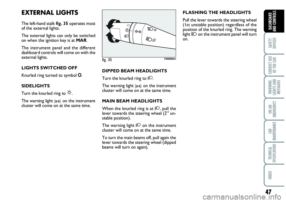
The left-hand stalk fig. 35operates most
of the external lights.
The external lights can only be switched
on when the ignition key is at MAR.
The instrument panel and the different
dashboard controls will come on with the
external lights.
LIGHTS SWITCHED OFF
Knurled ring turned to symbol O.
SIDELIGHTS
Turn the knurled ring to
6.
The warning light
3on the instrument
cluster will come on at the same time.DIPPED BEAM HEADLIGHTS
Turn the knurled ring to
2.
The warning light
3on the instrument
cluster will come on at the same time.
MAIN BEAM HEADLIGHTS
When the knurled ring is at
2, pull the
lever towards the steering wheel (2ndun-
stable position).
The warning light
2on the instrument
cluster will come on at the same time.
To turn the main beams off, pull again the
lever towards the steering wheel (dipped
beams will turn on again).FLASHING THE HEADLIGHTS
Pull the lever towards the steering wheel
(1st unstable position) regardless of the
position of the knurled ring. The warning
light
1on the instrument panel will turn
on.
fig. 35F0M0060m
Page 50 of 207
48
SAFETY
DEVICES
CORRECT USE
OF THE CAR
WARNING
LIGHTS AND
MESSAGES
IN AN
EMERGENCY
CAR
MAINTENANCE
TECHNICAL
SPECIFICATIONS
INDEX
DASHBOARD
AND CONTROLS
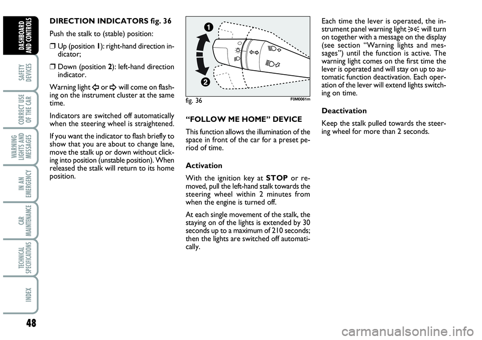
DIRECTION INDICATORS fig. 36
Push the stalk to (stable) position:
❒Up (position 1): right-hand direction in-
dicator;
❒Down (position 2): left-hand direction
indicator.
Warning light
Îor ¥will come on flash-
ing on the instrument cluster at the same
time.
Indicators are switched off automatically
when the steering wheel is straightened.
If you want the indicator to flash briefly to
show that you are about to change lane,
move the stalk up or down without click-
ing into position (unstable position). When
released the stalk will return to its home
position.“FOLLOW ME HOME” DEVICE
This function allows the illumination of the
space in front of the car for a preset pe-
riod of time.
Activation
With the ignition key at STOPor re-
moved, pull the left-hand stalk towards the
steering wheel within 2 minutes from
when the engine is turned off.
At each single movement of the stalk, the
staying on of the lights is extended by 30
seconds up to a maximum of 210 seconds;
then the lights are switched off automati-
cally. Each time the lever is operated, the in-
strument panel warning light
3will turn
on together with a message on the display
(see section “Warning lights and mes-
sages”) until the function is active. The
warning light comes on the first time the
lever is operated and will stay on up to au-
tomatic function deactivation. Each oper-
ation of the lever will extend lights switch-
ing on time.
Deactivation
Keep the stalk pulled towards the steer-
ing wheel for more than 2 seconds.
fig. 36F0M0061m
Page 51 of 207

49
SAFETY
DEVICES
CORRECT USE
OF THE CAR
WARNING
LIGHTS AND
MESSAGES
IIN AN
EMERGENCY
CAR
MAINTENANCE
TECHNICAL
SPECIFICATIONS
INDEX
DASHBOARD
AND CONTROLS
WINDOW WASHING
The right stalk fig. 37controls windscreen
wiper/washer and heated rear window
wiper/washer operation.
WINDSCREEN WASHER/
WIPER
The device can only work when the igni-
tion key is atMAR.
The stalk ring nut can be moved to four
different positions:
Owindscreen wiper off;
≤intermittent;
≥continuous slow;
¥continuos fast.
Moving the stalk to A(unstable position)
operation is limited to the time the stalk
is held in this position. When the stalk is
released it returns to its original position
automatically stopping the wiper.Never use the window wiper
to remove ice or snow from
the windscreen. In these con-
ditions, the wiper is submitted
to excessive effort that results in motor
protection cutting in and wiper opera-
tion inhibition for few seconds as a con-
sequence. If operation is not restored
(also after restarting the car by the ig-
nition key) contact Abarth Dealership.
With ring nut at
≤, wiping speed is au-
tomatically adapted to the car speed.
IMPORTANT Replace wiper blades as
specified in section “Car maintenance”.
fig. 37F0M0062m
Page 52 of 207
50
SAFETY
DEVICES
CORRECT USE
OF THE CAR
WARNING
LIGHTS AND
MESSAGES
IN AN
EMERGENCY
CAR
MAINTENANCE
TECHNICAL
SPECIFICATIONS
INDEX
DASHBOARD
AND CONTROLS
RAIN SENSOR (for versions/
markets, where provided)
The rain sensor is located behind the dri-
ving mirror in contact with the windscreen
and has the purpose of automatically ad-
just, during the intermittent operation, the
frequency of the windscreen wiper
strokes as to the rain intensity.
IMPORTANT Keep clean the glass in the
sensor area.
Activation
Move the right-hand stalk knurled ring to
≤fig. 37.
The activation of the rain sensor is sig-
nalled by a control acquisition “stroke”.
Through the set up menu it is possible to
increase the sensitivity of the rain sensor.
The increase of the sensitivity of the rain
sensor is signalled by a control and acqui-
sition “stroke”.
Operating the windscreen washer with
the rain sensor activated the normal wash-
ing cycle is performed at the end of which
the rain sensor resumes its normal auto-
matic function.Deactivation
Change the stalk knurled ring position
from
≤fig. 37or turn the ignition key
to STOP.
At next engine starting (key at MAR), the
sensor will not be reactivated even if the
knurled ring is still at
≤fig. 37. To ac-
tivate the rain sensor you have to move
the knurled ring from
≤to another po-
sition and then again to
≤.
Rain sensor activation will be indicated by
at least one wiper “stroke” even if the
windscreen is dry.
The rain sensor is able to recognize and
automatically adjust itself in the presence
of the following particular conditions:
❒ impurities on the controlled surface
(salt, dirt, etc.);
❒difference between day and night.
IMPORTANT Streaks of water may cause
unrequired blade moving. “Smart washing” function
Pulling the stalk towards the steering wheel
(unstable position) operates the wind-
screen washer.
Keeping the stalk pulled for more than half
a second, with just one movement it is
possible to operate the washer jet and the
wiper at the same time.
The wiper stops working three strokes af-
ter releasing the stalk.
A further stroke after 6 seconds com-
pletes the wiping operation.