Abarth Punto Evo 2012 Owner handbook (in English)
Manufacturer: ABARTH, Model Year: 2012, Model line: Punto Evo, Model: Abarth Punto Evo 2012Pages: 270, PDF Size: 3.53 MB
Page 151 of 270
150
KNOWING
YOUR VEHICLE
SAFETY
STARTING
AND DRIVING
WARNING LIGHTS
AND MESSAGES
IN AN
EMERGENCY
MAINTENANCE
AND CARE
TECHNICAL
SPECIFICATIONS
CONTENTS
Strong radio-frequency interference
could inhibit the regular operation of
the TPMS system.
This condition will be indicated by a message.
The message will disappear automatically as
soon as the interference ceases to disturb the
system.
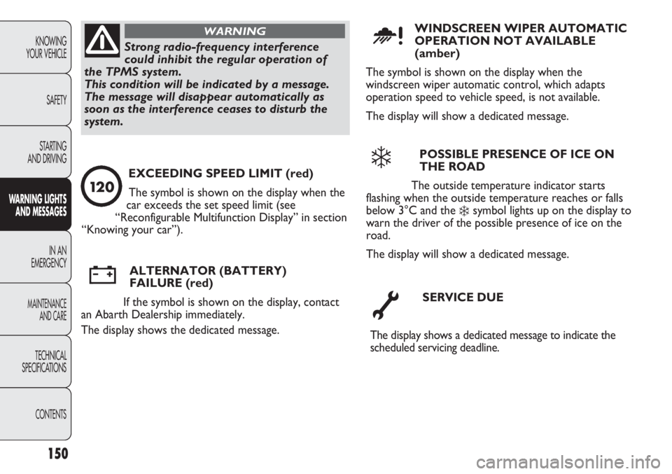
WARNINGWINDSCREEN WIPER AUTOMATIC
OPERATION NOT AVAILABLE
(amber)
The symbol is shown on the display when the
windscreen wiper automatic control, which adapts
operation speed to vehicle speed, is not available.
The display will show a dedicated message.
u
POSSIBLE PRESENCE OF ICE ON
THE ROAD
The outside temperature indicator starts
flashing when the outside temperature reaches or falls
below 3°C and the
❄symbol lights up on the display to
warn the driver of the possible presence of ice on the
road.
The display will show a dedicated message.
❄
SERVICE DUE
The display shows a dedicated message to indicate the
scheduled servicing deadline.
õ
ALTERNATOR (BATTERY)
FAILURE (red)
If the symbol is shown on the display, contact
an Abarth Dealership immediately.
The display shows the dedicated message.w
EXCEEDING SPEED LIMIT (red)
The symbol is shown on the display when the
car exceeds the set speed limit (see
“Reconfigurable Multifunction Display” in section
“Knowing your car”).
12 0
Page 152 of 270

STARTING THE ENGINE
EMERGENCY STARTING
If the instrument panel warning light
Ystays on
permanently, contact an Abarth Dealership immediately.
IN AN EMERGENCY
In an emergency we recommend that you call the free-phone number found on the Warranty Booklet. You can
also find the Abarth Dealership nearest to you on the web site www.fiat.com.
This procedure must be performed by
expert personnel because incorrect
actions could cause electrical discharge of
considerable intensity. Furthermore, battery
fluid is poisonous and corrosive: avoid contact
with skin and eyes. Keep naked flames away
from the battery. No smoking. Do not cause
sparks.
WARNING
IMPORTANT For the jump starting procedure, refer to
“Knowing your car” section, paragraph “Start&Stop
system”.
fig. 126F0U187Ab
151
KNOWING
YOUR VEHICLE
SAFETY
STARTING
AND DRIVING
WARNING LIGHTS
AND MESSAGES
IN AN
EMERGENCY
MAINTENANCE
AND CARE
TECHNICAL
SPECIFICATIONS
CONTENTS
JUMP STARTING fig. 126
If the battery is flat, the engine may be started using an
auxiliary battery with the same capacity or a little higher
than the flat one. It is advisable to contact an Abarth
Dealership to check/replace the battery.
Page 153 of 270
152
KNOWING
YOUR VEHICLE
SAFETY
STARTING
AND DRIVING
WARNING LIGHTS
AND MESSAGES
IN AN
EMERGENCY
MAINTENANCE
AND CARE
TECHNICAL
SPECIFICATIONS
CONTENTS
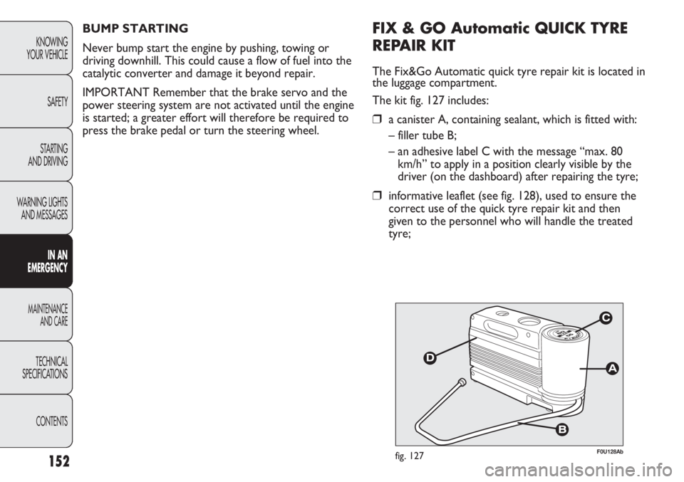
F0U128Abfig. 127
FIX & GO Automatic QUICK TYRE
REPAIR KIT
The Fix&Go Automatic quick tyre repair kit is located in
the luggage compartment.
The kit fig. 127 includes:
❒a canister A, containing sealant, which is fitted with:
– filler tube B;
– an adhesive label C with the message “max. 80
km/h” to apply in a position clearly visible by the
driver (on the dashboard) after repairing the tyre;
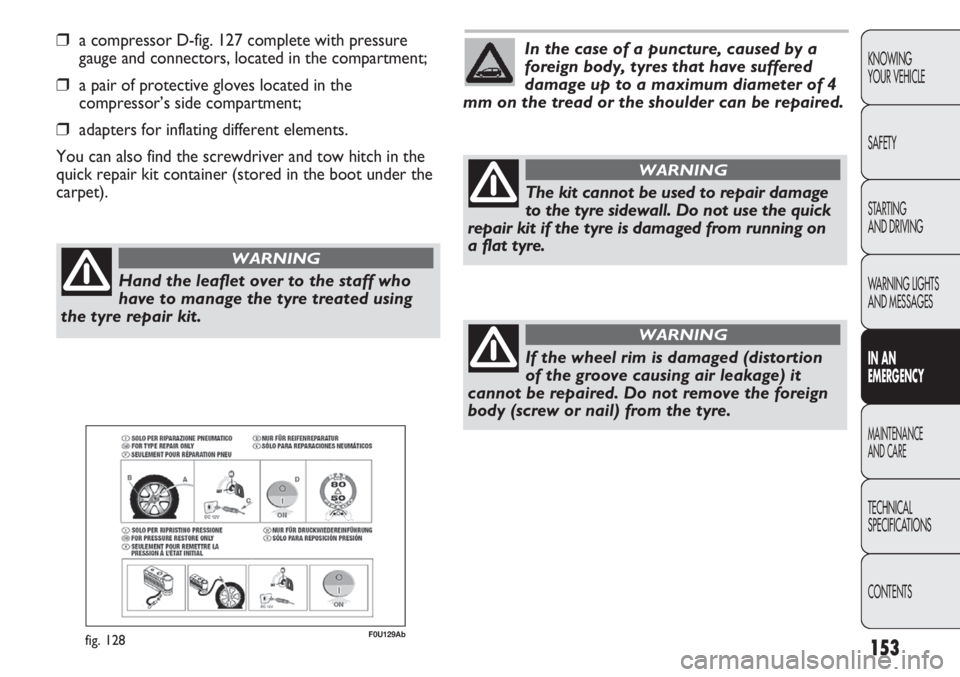
❒informative leaflet (see fig. 128), used to ensure the
correct use of the quick tyre repair kit and then
given to the personnel who will handle the treated
tyre; BUMP STARTING
Never bump start the engine by pushing, towing or
driving downhill. This could cause a flow of fuel into the
catalytic converter and damage it beyond repair.
IMPORTANT Remember that the brake servo and the
power steering system are not activated until the engine
is started; a greater effort will therefore be required to
press the brake pedal or turn the steering wheel.
Page 154 of 270
153
KNOWING
YOUR VEHICLE
SAFETY
STARTING
AND DRIVING
WARNING LIGHTS
AND MESSAGES
IN AN
EMERGENCY
MAINTENANCE
AND CARE
TECHNICAL
SPECIFICATIONS
CONTENTS
❒a compressor D-fig. 127 complete with pressure
gauge and connectors, located in the compartment;
❒a pair of protective gloves located in the
compressor’s side compartment;
❒adapters for inflating different elements.
You can also find the screwdriver and tow hitch in the
quick repair kit container (stored in the boot under the
carpet).
F0U129Abfig. 128
Hand the leaflet over to the staff who
have to manage the tyre treated using
the tyre repair kit.
WARNING
In the case of a puncture, caused by a
foreign body, tyres that have suffered
damage up to a maximum diameter of 4
mm on the tread or the shoulder can be repaired.
The kit cannot be used to repair damage
to the tyre sidewall. Do not use the quick
repair kit if the tyre is damaged from running on
a flat tyre.
WARNING
If the wheel rim is damaged (distortion
of the groove causing air leakage) it
cannot be repaired. Do not remove the foreign
body (screw or nail) from the tyre.
WARNING
Page 155 of 270
Replace the bottle containing out of date
sealant fluid. Dispose of the bottle and
the sealant liquid properly. Dispose of
according to the national and local regulations in
force.
154
KNOWING
YOUR VEHICLE
SAFETY
STARTING
AND DRIVING
WARNING LIGHTS
AND MESSAGES
IN AN
EMERGENCY
MAINTENANCE
AND CARE
TECHNICAL
SPECIFICATIONS
CONTENTS
The cylinder contains ethylene glycol.
Contains latex: may cause an allergic
reaction. Harmful if swallowed. Irritant for the
eye. May cause irritation if inhaled or on
contact. Avoid contact with eyes, skin and
clothes. In the event of contact, wash
immediately with plenty of water. Do not
induce vomiting if swallowed. Rinse your mouth
and drink plenty of water. Call a doctor
immediately. Keep away from children. The
product must not be used by asthmatics. Do not
breathe in the vapours during insertion and
suction. Call a doctor immediately if allergic
reactions are noted. Store the bottle in the
specific compartment, away from sources of
heat. The sealant fluid has a limited life.
WARNINGIMPORTANT INFORMATION:
The sealing fluid of the quick tyre repair kit is effective at
external temperatures of between -20 °C and +50 °C.
The sealing fluid will expire.
Do not operate the compressor for
longer than 20 consecutive minutes. Risk
of overheating. The quick repair kit is not
suitable for definitive repairs. Tyres may only be
repaired temporarily.
WARNING
Page 156 of 270
F0U131Abfig. 130F0U130Abfig. 129
INFLATION PROCEDURE
Wear on the protective gloves provided
together with quick tyre repair kit.
WARNING
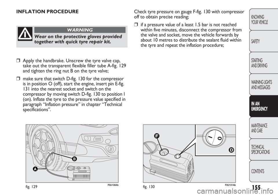
Check tyre pressure on gauge F-fig. 130 with compressor
off to obtain precise reading;
❒if a pressure value of a least 1.5 bar is not reached
within five minutes, disconnect the compressor from
the valve and socket, move the vehicle forwards by
about 10 metres to distribute the sealant fluid within
the tyre and repeat the inflation procedure;
155
KNOWING
YOUR VEHICLE
SAFETY
STARTING
AND DRIVING
WARNING LIGHTS
AND MESSAGES
IN AN
EMERGENCY
MAINTENANCE
AND CARE
TECHNICAL
SPECIFICATIONS
CONTENTS
❒Apply the handbrake. Unscrew the tyre valve cap,
take out the transparent flexible filler tube A-fig. 129
and tighten the ring nut B on the tyre valve;
❒make sure that switch D-fig. 130 for the compressor
is in position O (off), start the engine, insert pin E-fig.
131 into the nearest socket and switch on the
compressor by moving switch D-fig. 130 to position I
(on). Inflate the tyre to the pressure value specified in
paragraph “Inflation pressure” in chapter “Technical
specifications”.
Page 157 of 270

156
KNOWING
YOUR VEHICLE
SAFETY
STARTING
AND DRIVING
WARNING LIGHTS
AND MESSAGES
IN AN
EMERGENCY
MAINTENANCE
AND CARE
TECHNICAL
SPECIFICATIONS
CONTENTS
F0U133Abfig. 132
❒after driving for about 10 minutes, stop and check
the tyre pressure fig. 132 again; remember to put the
handbrake on;
Apply the adhesive label in a position
clearly visible by the driver as a reminder
that the tyre has been treated with the quick
repair kit. Drive carefully, particularly on bends.
Do not exceed 80 km/h. Do not accelerate and
brake suddenly.
WARNING
F0U132Abfig. 131
❒if in this case a pressure of at least 1.8 bar is not
reached within five minutes of switching on the
compressor, do not continue driving because the tyre
is too damaged and the hold cannot be guaranteed
using the kit. Contact an Abarth Dealership;
❒if the tyre reaches the pressure specified in the
“Inflation pressure” paragraph in the “Technical
Specifications” chapter, start driving immediately;
Page 158 of 270

157
KNOWING
YOUR VEHICLE
SAFETY
STARTING
AND DRIVING
WARNING LIGHTS
AND MESSAGES
IN AN
EMERGENCY
MAINTENANCE
AND CARE
TECHNICAL
SPECIFICATIONS
CONTENTS
Inform the dealership that the tyre has
been repaired using the quick tyre repair
kit. Hand the instruction brochure over to the
personnel charged with treating the tyre
repaired with the kit.
WARNING
FOR CHECKING AND RESTORING
PRESSURE ONLY
The compressor can also be used solely for restoring
pressure. Release the quick coupling and connect it
directly to the tyre valve fig. 133; in this way, the
cylinder will not be connected to the compressor and
no sealant will be injected.
F0U134Abfig. 133
If the pressure has fallen below 1.8 bar,
do not drive any further: the automatic
Fix&Go Automatic quick tyre repair kit cannot
guarantee the correct hold because the tyre is
too damaged. Contact an Abarth Dealership.
WARNING
❒if at least 1.8 bar pressure is read, restore the correct
pressure (with engine running and handbrake on) and
restart;
❒drive with the utmost care to the nearest Abarth
Dealership.
Page 159 of 270

CHANGING A BULB
GENERAL INSTRUCTIONS
❒When a light is not working, check that the
corresponding fuse is intact before changing a bulb.
For the location of fuses, refer to the paragraph “If a
fuse blows” in this section;
❒before changing a bulb check the contacts for
oxidation;
❒burnt bulbs must be replaced by others of the same
type and power;
❒always check the height of the headlight beam after
changing a bulb for safety reasons.
158
KNOWING
YOUR VEHICLE
SAFETY
STARTING
AND DRIVING
WARNING LIGHTS
AND MESSAGES
IN AN
EMERGENCY
MAINTENANCE
AND CARE
TECHNICAL
SPECIFICATIONS
CONTENTS
Changes or repairs to the electrical
system (electronic control units) carried
out incorrectly and without due consideration
for the technical specifications of the system
may lead to malfunctioning and generate a fire
hazard.
WARNING
Halogen lamps contain pressurised gas.
If they break, glass fragments could fly
everywhere.
WARNING
F0U135Abfig. 134
CYLINDER REPLACEMENT
PROCEDURE
To replace the cylinder, proceed as follows:
❒disconnect A-fig. 134;
❒turn the bottle anticlockwise to replace and raise it;
❒fit the new cylinder and turn it clockwise;
❒connect connection A to the canister and fit the
transparent tube B in the special compartment.
Page 160 of 270

159
KNOWING
YOUR VEHICLE
SAFETY
STARTING
AND DRIVING
WARNING LIGHTS
AND MESSAGES
IN AN
EMERGENCY
MAINTENANCE
AND CARE
TECHNICAL
SPECIFICATIONS
CONTENTS
Halogen bulbs must be handled by holding
the metallic part only. Touching the
transparent part of the bulb with your
fingers may reduce the intensity of the light
emitted and even compromise the life of the bulb
itself. In the event of accidental contact, wipe the
bulb with an alcohol-soaked cloth and leave to dry.
fig. 135F0U137Ab
IMPORTANT The internal surface of the light may
appear slightly misty: this does not indicate a fault, and is
actually caused by low temperature and the degree of
humidity in the air. Misting will rapidly disappear when
the headlights are switched on. The presence of drops
inside the headlights indicates infiltration of water.
Contact an Abarth Dealership.
TYPES OF BULBS
Different types of bulbs fig. 135 are installed on the car:
A Glass bulbs: clipped into position.
Pull to remove.
B Bayonet type bulbs: to remove this type of bulb from
its holder, press the bulb and turn it anticlockwise.C Tubular bulbs: release them from their contacts to
remove.
D-E Halogen bulbs: to remove the bulb, release the clip
holding the bulb in place.