ACURA INTEGRA 1994 Service Repair Manual
Manufacturer: ACURA, Model Year: 1994, Model line: INTEGRA, Model: ACURA INTEGRA 1994Pages: 1413, PDF Size: 37.94 MB
Page 101 of 1413
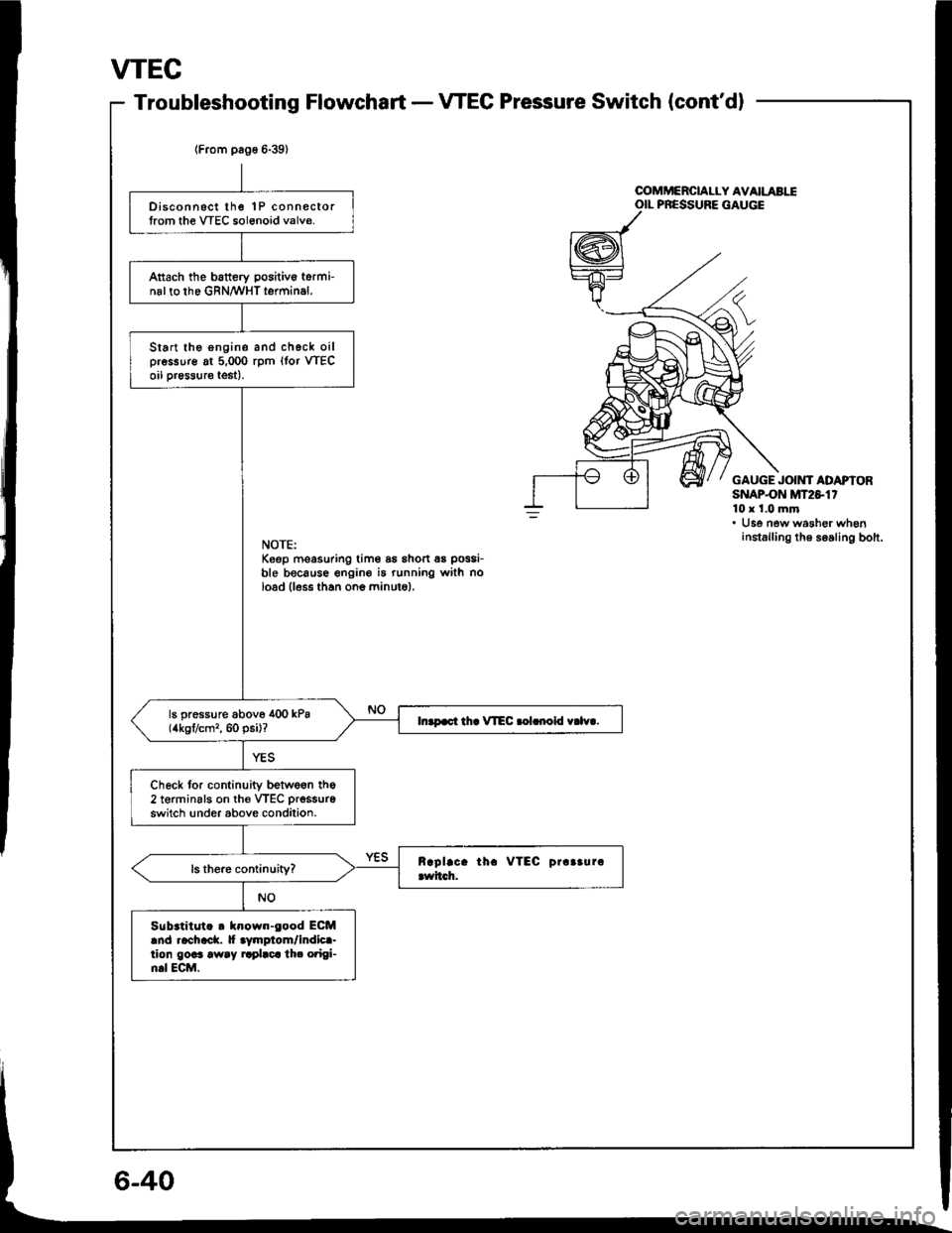
VTEC
Troubleshooting FlowchartVTEC Pressure Switch (cont'dl
lFrom pag6 6-39)
Disconnsct lhe 1P connectortrom the VTEC sol6noid valve.
Attach the battery positivo torminal to the GRN/WHT terminal.
Start the engine and chgck oilpressure at 5,000 rpm (lor VTECoil pr€ssure test).
ls pressure above 400 kPa(4kgt/cm,, 60 psi)?In.p.ct th. VIEC .olrnoid v.lv..
Check tor continuity betwe6n the2 terminsls on th€ VTEC prsssure
switch !nder above condition.
Sub.titut. . klown-eood ECMand rachack. |f aymplom/indica-tion goaa away rrplaca th. o?igi-n.l ECM.
u
OOMMERCIALLY AVAILABIIOIL PRESSURE GAUGE
GAUGE JOIMf ADAPIORSNAPON MT2S1'10x 1.0 mm. Use new washer wheninstalling th6 soaling bolt.NOTE:Keep moasuring tim6 as shon 6s possi-
ble because engine i5 running with noload lless than ono minuto).
Page 102 of 1413
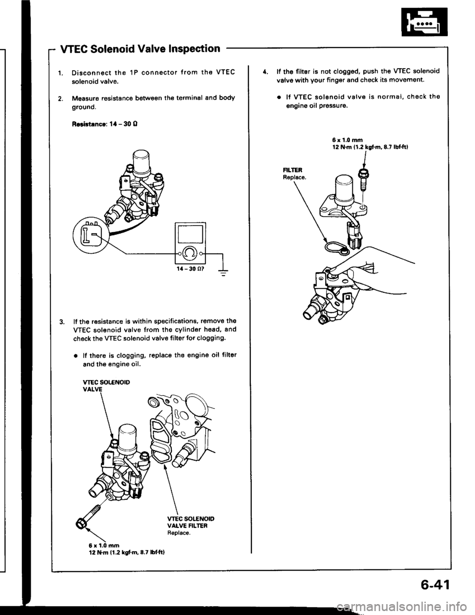
WEC Solenoid Valve Inspection
Disconnect the 1P connector trom the VTEC
solenoid valve.
M€asurs resistance between th€ terminal 8nd body
grouno.
R.3bt!nc!: 1l - 30 O
lf the resistance is within specificstions, romove the
WEC sol€noid valve from the cvlindor hsad, and
check the VTEC solenoid valve filter for clogging.
. lf there is clogging, replacs the engin€ oil filter
and the engine oil.
VTEC SOT.CNOTD
12 tTln 11.2 kg[.m,8.7 lbttt]
6-41
4. lf th6 filter is not clogged, push the VTEC solenoid
valv€ with your finger and check its movement.
. lf VTEC solsnoid valve is normal, check the
engins oil pr€ssure.
6x1.0mm
Page 103 of 1413
VTEC
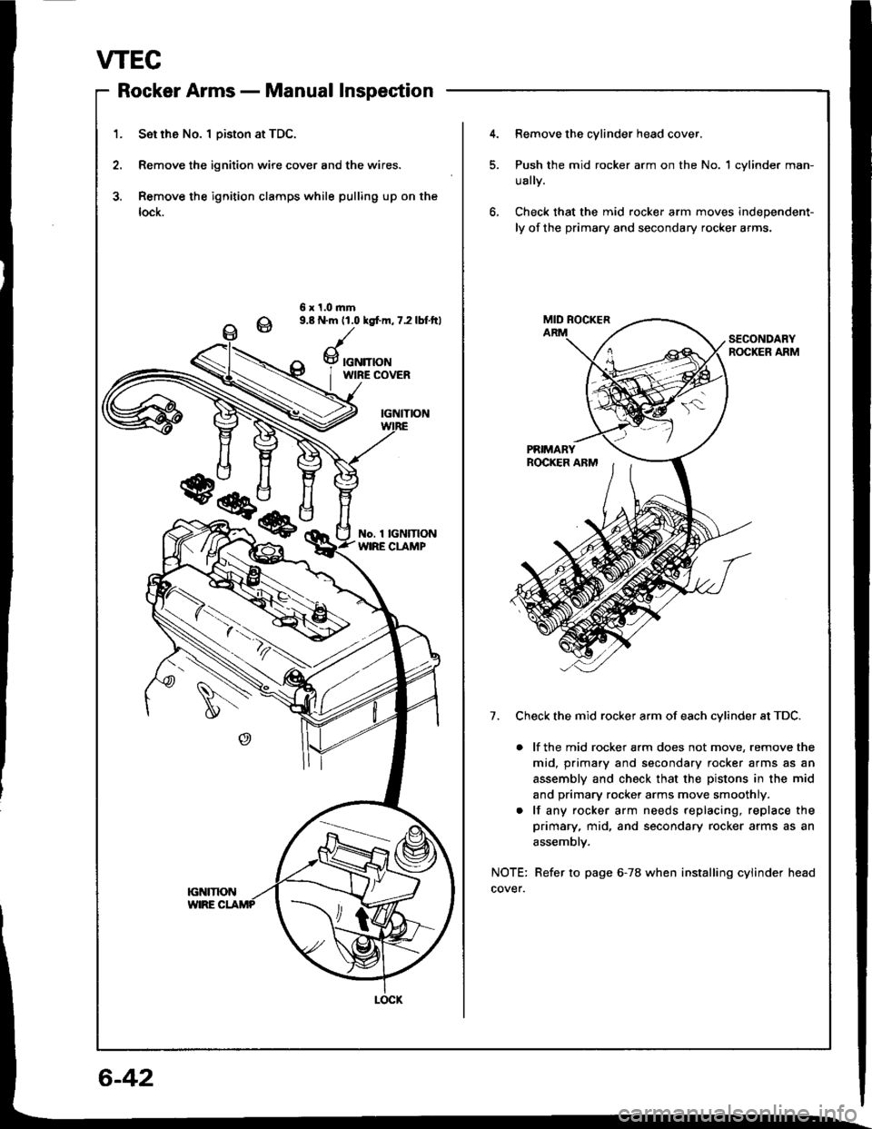
Rocker Armsnlrungf rtrrrri' - rYrorrtrcr rrrDPEUtrl,rl
1. Set rh6 No. I Diston at TDC.
2. Remove the ignition wire cover and the wires.
3. Remove the ignition clamps while pulling up on the
lock.
4.Remove the cylinder head cover.
Push the mid rocker arm on the No. 1 cylinder man-
ually.
Check that the mid rocker arm moves independent-
ly of the primary and secondary rocker arms.
6 x 1.0.nm9.8 N.m 11.0 lgfm, 7.2 lbf.ftl
SECONDARYROCKER ARM
7. Check the mid rocker arm of each cvlinder at TDC.
. lf the mid rocker arm does not move, remove the
mid, primary and secondary rocker arms as an
assembly and check that the pistons in the mid
and primary rocker arms move smoothly.
. lf any rocker arm needs replacing, replace the
primary, mid, and secondary rocker arms as an
assemblv.
NOTE: Refer to page 6-78 when installing cylinder head
cover.
w
Page 104 of 1413
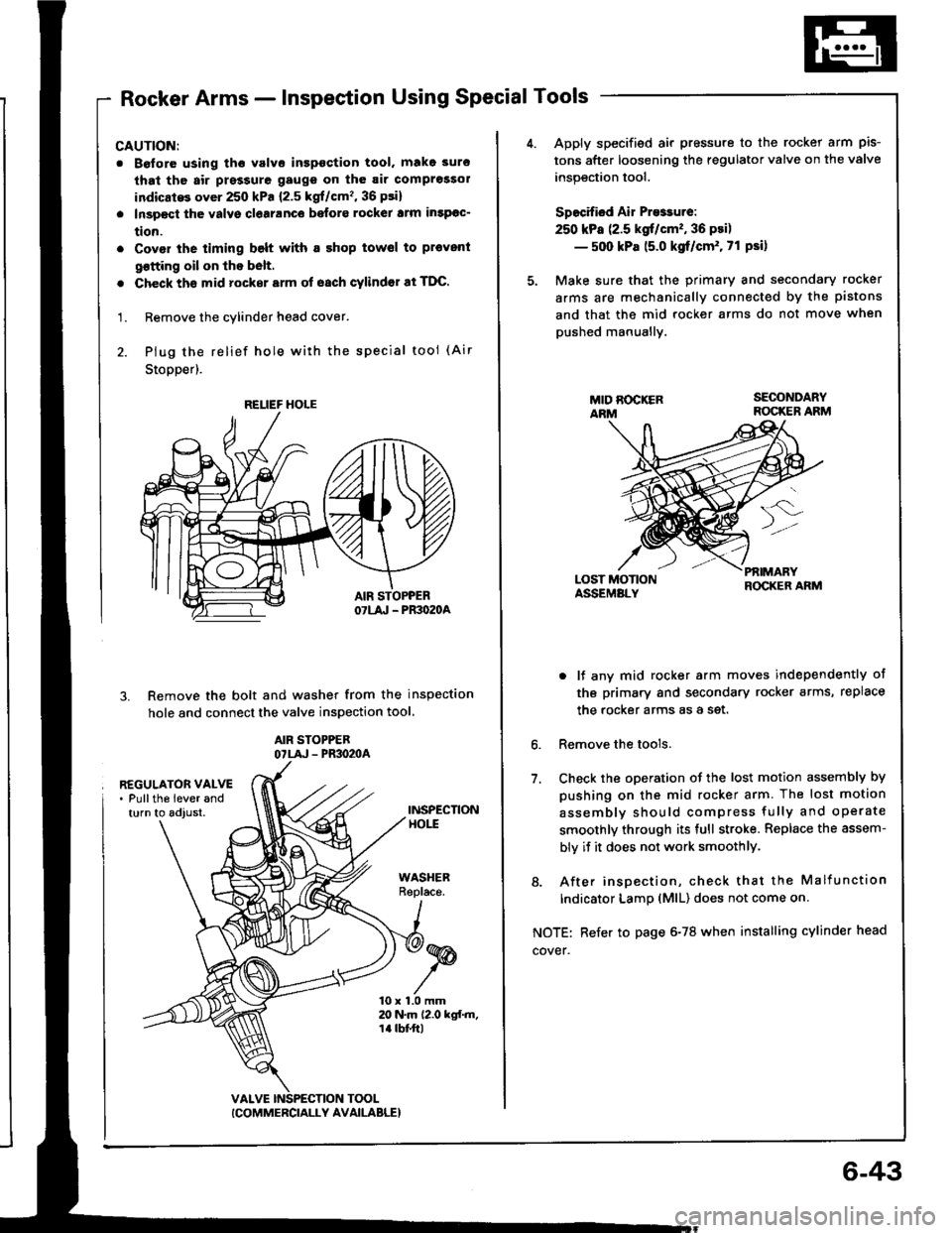
Rocker Arms - Inspection Using Special Tools
CAUTION:
. Boforo using tho valvo inspoction tool. make 3uro
that th6 air prsssure gaugs on th6 air comprossol
indicatG over 250 kPa {2.5 kgf/cm'�, 36 psi}
. Inspect the valvs clearanco befors rockel lrm insPoc-
tion.
. Covor the timing belt with a shop towsl to pl€vent
qotting oil on lhe b6lt.
. Check ths mid rocker srm of oach cylindor at TDC.
1. Remove the cylinder head cover.
2. Plug the relief hole wiih the special tool (Air
Stopper).
Remove the bolt and washer from the inspection
hole and connect the valve inspection tool
AIR STOPPEBOTLA' - PR3O2OA
3.
REGULATOR VALVE. Pullths lever andturn to adjust.INSPECTIONHOtt
WASHERReplace.
10 x 1.0 mm20 N.m 12.0 kgf.m,1a tbt'ft|
TOOL
RELIEF HOLE
ICOMMERCIALLY AVAILABLE}
6-43
Apply specified air pressure to the rocker arm pis-
tons after loosening the regulator valve on the valve
inspection tool.
Specified Air Presrure:
250 kPa (2.5 kgt/cm'�, 36 psi)
- 500 kPa 15.0 kgf/cm'. 71 Psi)
Make sure that the primary and secondary rocker
arms are mechanically connected by the pistons
and that the mid rocker arms do not move when
pushed manuallv.
LOST MOTIONASSEMALY
PfiIMARYROCKER ARM
6.
7.
o lf any mid rocker arm moves independently of
tho primary and secondary rocker arms, replace
the rocker arms as a set.
Remove the tools.
Check the oDeration of the lost motion assembly by
pushing on the mid rocker arm. The lost motion
assemblv should compress fully and operate
smoothly through its full stroke. Replace the assem-
bly if it does not work smoothlY.
8. After insoection, check that the Malfunction
Indicator LamD (MlL) does not come on
NOTE: Refer to page 6-78 when installing cylinder head
cover.
Page 105 of 1413
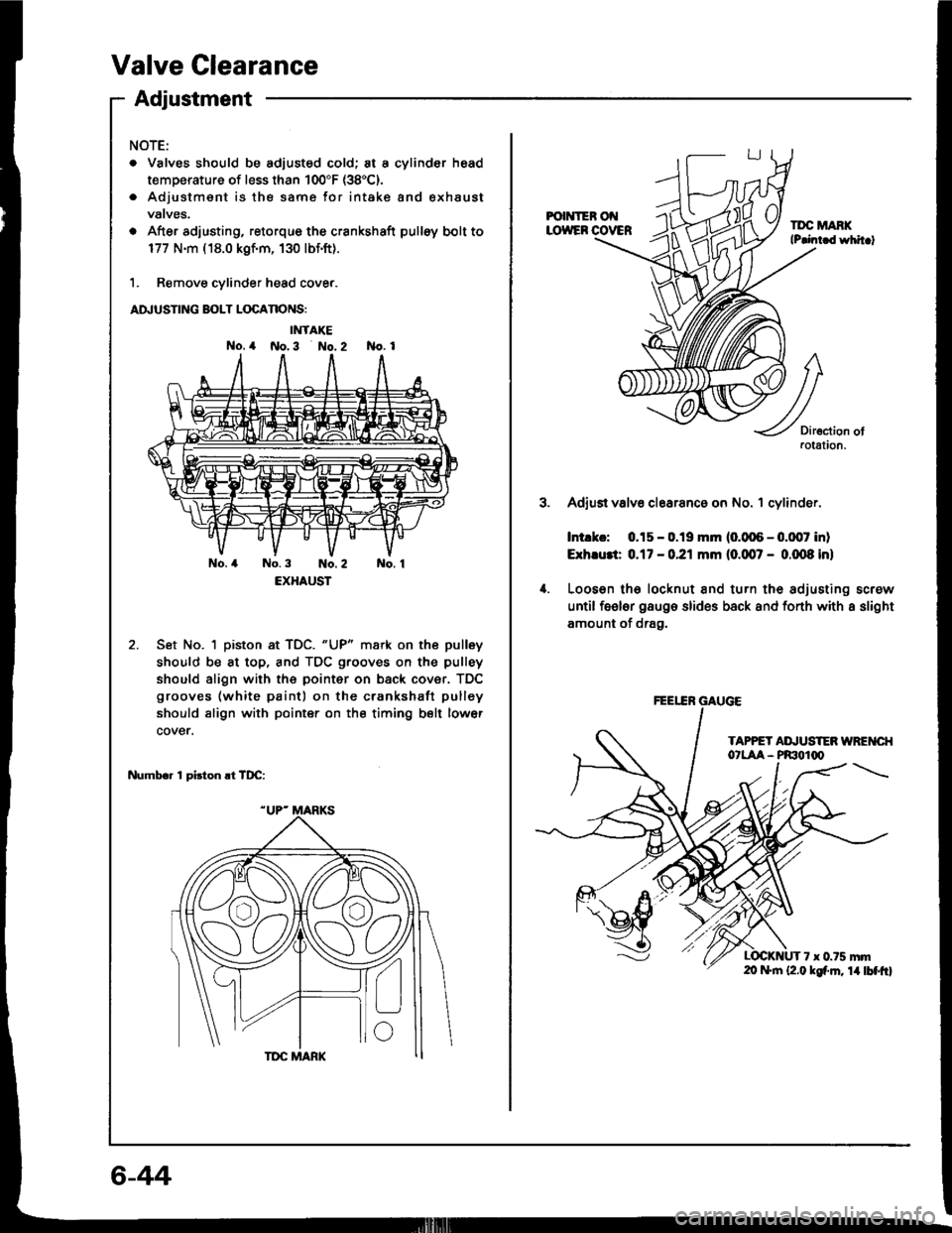
Valve Clearance
Adiustment
NOTE:
. Valves should be adjusted cold; at a cylinder head
temperature of less than 100"F (38'C).
. Adjustmsnt is the same for intake and exhaust
vatves.
o After adjusting, retorque the crankshaft pulloy bolt to
177 N.m ( 18.0 kgf.m, 130 lbf.ft).
1. Remove cylinder head cove..
ADJUSTING BOLT LOCANONS:
IMTAKE
No. 4 No.3 No. 2 No. 1
No.4 No.3 No.2 No. 1
EXHAUST
Set No. 1 piston at TDC. "UP" mark on the pulley
should be at top, and TDC grooves on the pulley
should align with the pointer on back cover. TDC
grooves (white paint) on the crankshatt pulley
should align with pointer on the timing belt lower
cover.
Numbr. 1 pirton .t TDC:
6-44
FOI{IER Ot{LOWEF COVERTDC MANKlP.int d whit.t
3.
4.
Diroction ofaotation.
Adjust valv6 clearanc6 on No. 1 cylinder.
Intlkc: 0.15 - 0.19 mm (0.006 - 0.0,07 inl
Exh.u3t 0.17 - 0.21 mm (0.007 - 0.m8 inl
Looson lh6 locknut and turn the adjusting screw
until feeler gaugo slides back and fonh with a slight
amount of drag.
TAPPET AI\,USTEN WREI{CI{O'LAA - PRIOIq'
7 x 0.75 mrn20 f+|n (2.0 kgf'm. 14lbtftl
FEEEN GAUGE
Page 106 of 1413
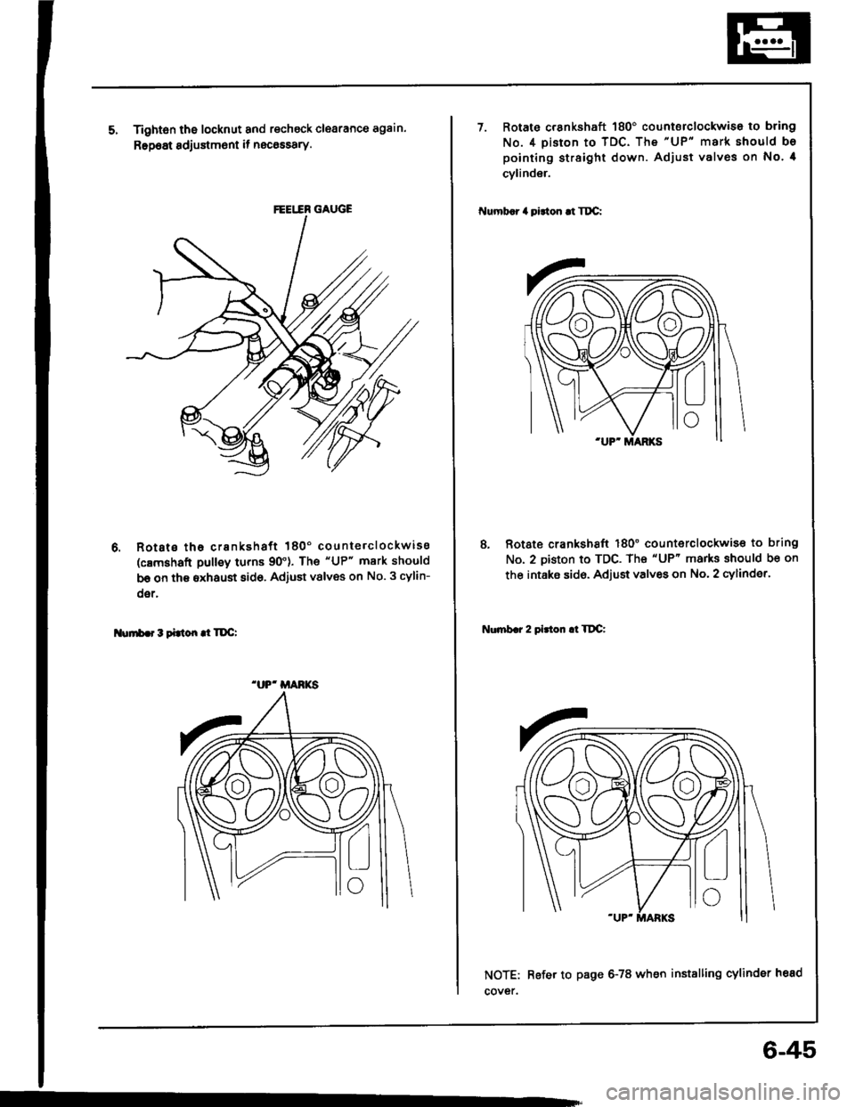
Tightsn the locknut and recheck clearance again.
Rep6at sdjustm6nt if necossary.
Rotsts tha crankshaft 180' counterclockwiss
(c8mshaft pulley turns 90'). The "UP" mark should
be on th€ sxhaust 8id6, Adiust vslves on No. 3 cylin-
oer,
Nurrb.r3tittondTDC:
FEEI.IR GAUGE
.UP' MANKS
7. Rotato crankshaft 180' countsrclockwise to bring
No.4 piston to TDC. The "UP" mark should bo
pointing straight down. Adjust valves on No. 4
cylinder.
Numb.r 4 pidon .t Tt C:
8, Rotate crankshaft 180" counterclockwis€ to bring
No. 2 piston to TDC. The "UP" marks should be on
the intaks sid6. Adjust valves on No. 2 cylinder.
Nonb.r 2 pirton .l TltC:
NOTE: Refer to page 6-78 when installing cylinder head
cover.
6-45
Page 107 of 1413
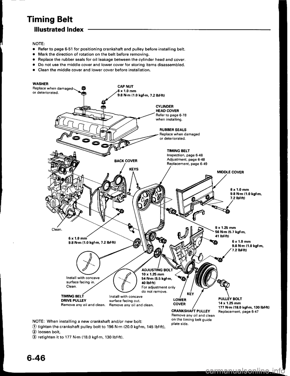
Timing Belt
. ReJerto page 6-51 for positioning crankshaft and pulley before installing belt.. Mark the direction of rotation on the belt before removing.
. Replace the rubber seals for oil leakage between the cylinder head and cover.. Do not use the middle cover and lower cover for storing items disassembled.
. Clean the middle cover and lower cover before installation.
lllustrated lndex
NOTE:
WASHERReplace whenCAP NUTx 1,0 mm9.8 N.m 11.0 kgf.m,7,2lbttrlor deteriorated.
CYLINDERHEAO COVERReter to page 6'78when installing.
RUBBER SEALSReplace when damagedor deteriorated,
TIMING BELTInsp€ctaon, page 6-48Adjustment. page 6-48R€placement. page 6'49
MIDDLE COVER
5xl,0mm9.8 N.m (1.0 kgt m,7.2 rbtftt
8 x 1.25 mm56 N.m 15.7 kgt m,41 tbtftl6x1.0mm9.8 N.m (1.0 kgt.m,7.2lbf ftl6x1.0mm9.8 N.m {1.0 kgl.m,7.2lbf.ftl
Installwith concavesurface lacing in.Clean.
TIMING SELDRIVE PULLEYRemove any oil and clean.
10 x 1.25 mm5a N.m 15.5 kgl.m.(} tbf.ftlFor adiustment onlydo not remove.
BOLTInstallwith concavesurface tacing out.Remove any oiland clesn.1il x 1.25 mm177 N.m 118,0 kgtm, 130lbtft)Replacement, page 6-47
COVER
PULLEYRemove any oil and cleanon the timing belt guideplate side.NOTE: When installing a new crankshaft and/or new bolt:
O tighten the crankshaft pulley bolr to 196 N.m (20.0 kgf.m. 145 lbf.ft),
@ loosen bolt,
@ retighten it to 177 N.m fl8.0 kgf.m, 130 lbnft).
3-E
6-46
Page 108 of 1413
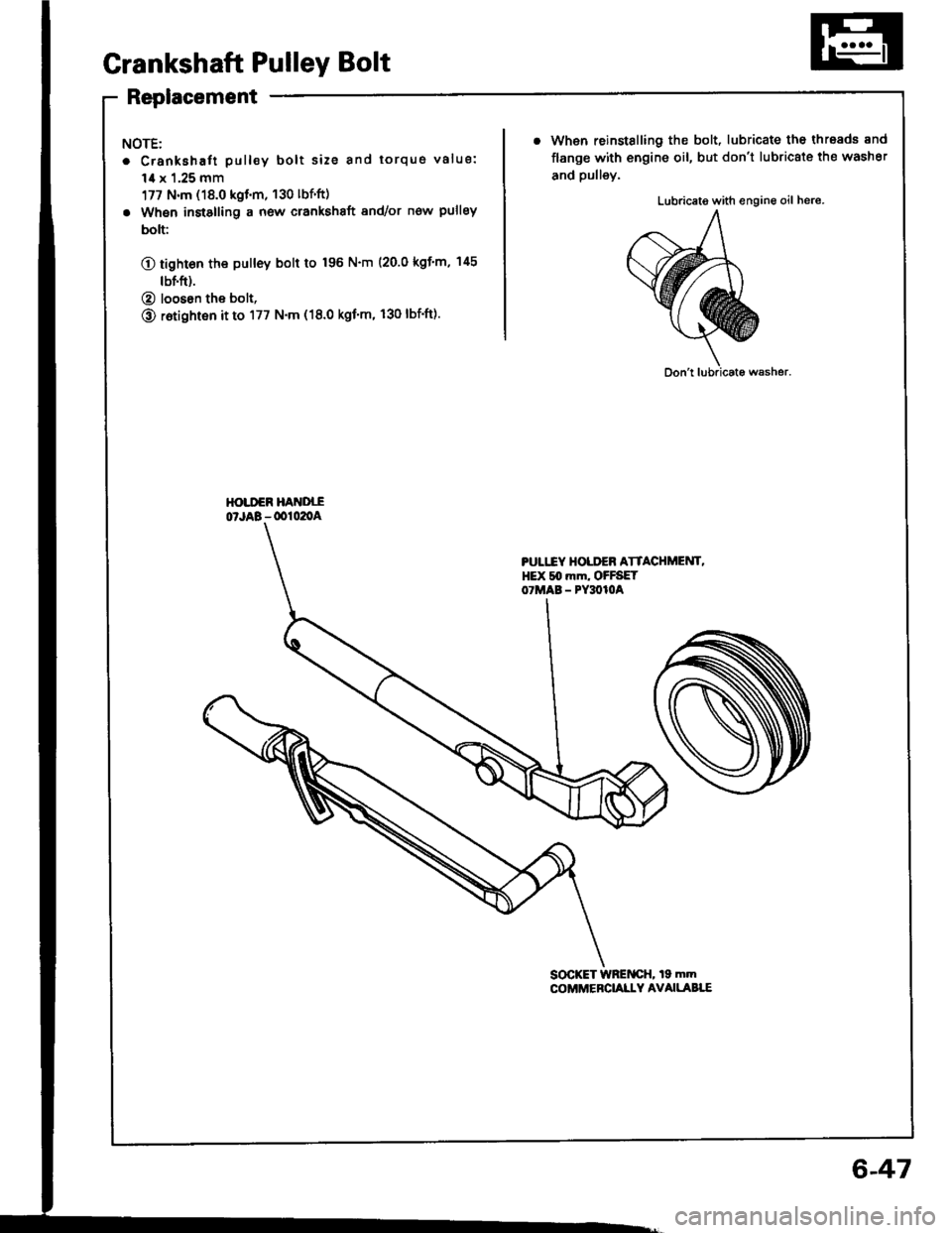
Grankshaft Pulley Bolt
Replacement
NOTE:
. Crankshaft pull€y bolt size and torqus value:
1,0 x 1.25 mm
177 N.m (18.0 kgt.m, 130 lbf'ft)
. When instslling a new crankshaft 8nd/or now pulley
bolt:
O tight6n the pulley bolt to 196 N'm (20.0 kgf'm, 145
tbf.ft).
@ looson the bolt,
@ r6tighten it to 177 N.m (18.0 kgf'm, 130 lbf'ft).
. When reinstalling the bolt, lubricate the thresds 8nd
flange with engine oil, but don't lubricate the washer
and pulley.
Lubriceto with engine oil hers.
SOCKET WRENCH, 19 mmCOi'MEBCI,ALLY AVAILABT.E
PULITY HOLDEB ATTACHMEUT,HEX slt mm, OFFSETOTMAB - PY3O1OA
6-47
Page 109 of 1413
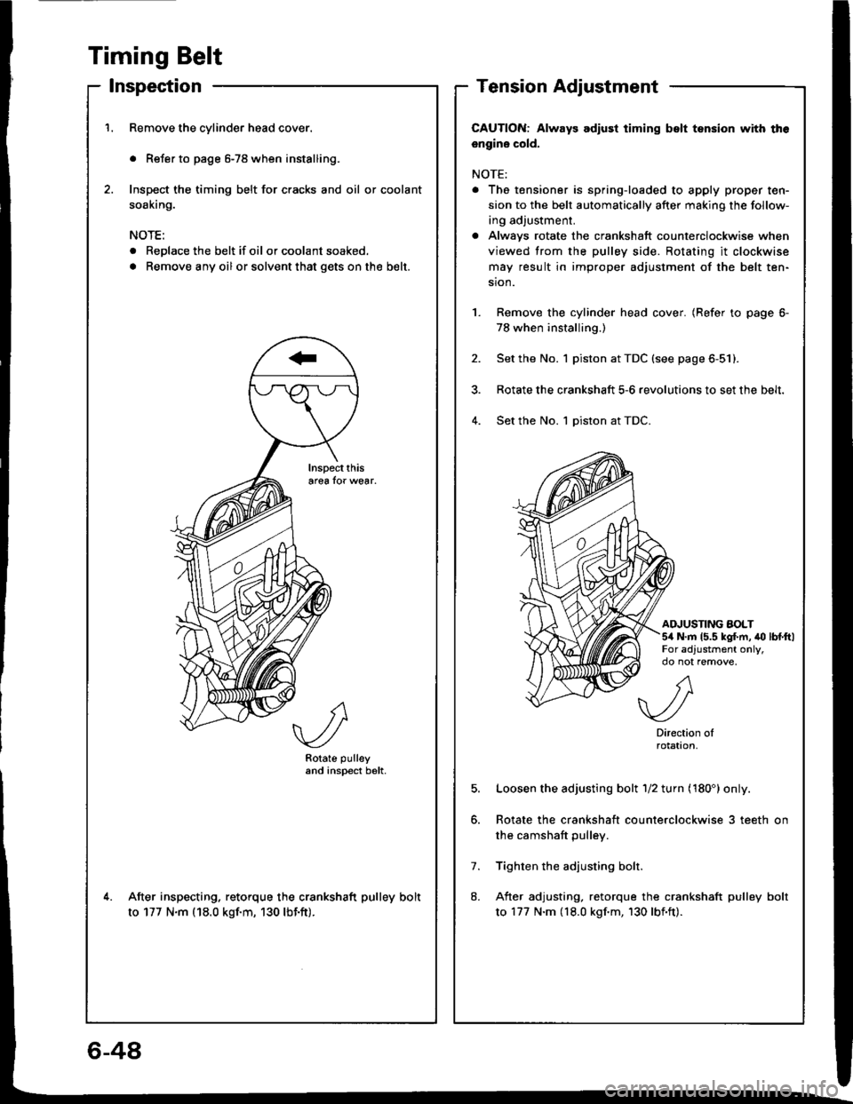
Timing Belt
lnspection
Remove the cylinder head cover.
. Refer to page 6-78 when installing.
Inspect the timing belt for cracks and oil or coolant
soaking.
NOTE:
. Replace the belt if oil or coolant soaked.
. Remove any oil or solvent that gets onthe b€lt.
Rotate pulleyand inspect b6lt.
After inspecting. retorque the crankshaft pulley bolt
to 177 N.m (18.0 kgf.m, 130 lbf.ft).
Tension Adjustment
CAUTION: Always adlust timing bslt tsnsion with th6
engine cold.
NOTE:
. The tensioner is spring-loaded to apply proper ten-
sion to the belt automatically after making the follow-
ing adjustment.
a Alwavs rotate the crankshaft counterclockwise when
viewed trom the pulley side. Rotating it clockwise
may result in improper adjustment of the belt ten-
sion.
Remove the cylinder head cover. (Refer to page 6-
78 when installing.)
Set the No. 1 piston at TDC (see page 6-51).
Rotate the crankshaft 5-6 revolutions to set the belt.
Set the No. 1 piston at TDC.4.
AINUSTING AOLT5/a N.m 15.5 kg{.m, to lbtftlFor adjustment only,
5.
7.
8.
A
.//\v-/
Directionrotat|on,
Loosen the adjusting bolt 1/2 turn (180') only.
Rotate the crankshaft counterclockwise 3 teeth on
the camshaft pulley.
Tighten the adjusting bolr.
After adjusting, retorque the crankshaft pulley bolt
to 177 N.m (18.0 kgf.m, 130 lbf'ft).
6-48
Page 110 of 1413
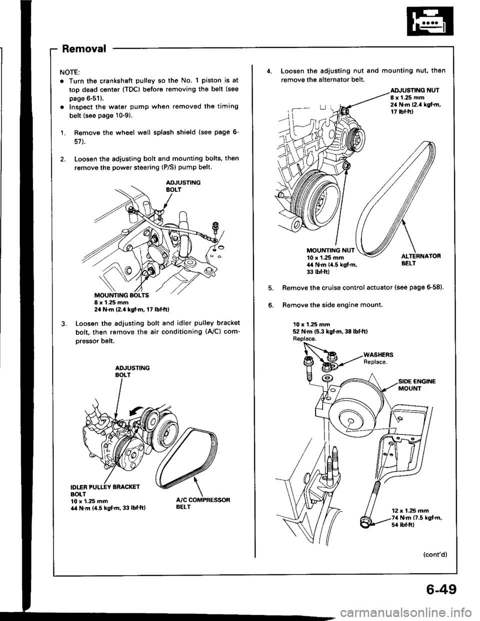
Removal
NOTE:
. Turn the crankshaft pulley so the No. 1 piston is at
top dead center {TDC) before removing the belt (see
page 6-51).
. Inspect the water pump when removed the timing
belt {see page 10-9).
Remove the wheel well splash shield (see page 6-
57 ).
Loosen the adiusting bolt and mounting bolts, then
remove the power steering (P/S) pump belt.
I x 1.25 mm2a N.m l2.a kgt.m, 17 lbt ttl
Loosen the adjusting bolt and idler pulley bracket
bolt, then remove the air conditioning (Ay'C) com-
oresso. belt.
D1INBOLT10 x 1.25 mmira N.m (4.5 kgf.m, 33 lbf'ttl
AOJUSTING
ADJUSNNG
BELT
4. Loosen the adiusting nut and mounting nut, then
remove the alternator belt.
NUTI x 1.25 mm24 N.m {2.a lgf.rn,17 tbf.ftl
MOUNTING NUT10 x 1.25 mm4,t N.m lia.5 kgl.m,33 tbt ftl
Remove the cruise control actuator (see page G58).
Bemove the side engine mount.
10 x 1.25 mm52 N.m 15.3 kgt m, 38 lbtftl
CNGINCMOUNT
12 x 1.25 mm74 N.m (7.5 kgt m,s4 lbf.trl
(cont'd)
6-49