transmission oil ACURA INTEGRA 1994 Service Repair Manual
[x] Cancel search | Manufacturer: ACURA, Model Year: 1994, Model line: INTEGRA, Model: ACURA INTEGRA 1994Pages: 1413, PDF Size: 37.94 MB
Page 25 of 1413
ll
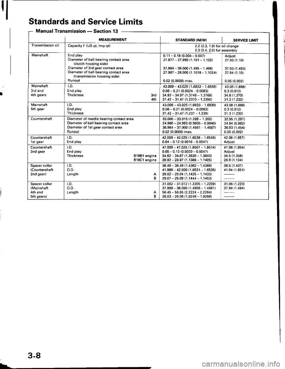
Standards andService Limits
Manual TransmissionSection 13
MEASUREMENTSTANDARD {NEWISERVICE UMIT
Transmission oilCapacity f {US qt, lmp q02.2 {2.3, 1.9}lor oilchange2.3 (2.4, 2.0) lor assembly
MainshaftEnd playDiameter ot ball bearing contact area(clutch housing side)Diameter of 3rd gear contact areaDiameter of ball besring contact area(transmission housing side)Runo!t
0.11 - 0.18 {0,004 - 0.007)27 .977 - 27 s90 l.1.101 - 1 .1021
37.984 - 38.000 {1.495 - 1.495}27.987 - 28.000 {r.1018 - 1.1024}
0.02 (0.0008) max.
Adjust27.93 (1.10)
37.93 {1.493)21 .94 /.1.10!'
0.05 (0.002)
Mainshafi
3rd and4lh gears
t.D.
End playThickness3rd4th
43.009 - 43.025 11.6933 , 1.6939)0.06 - 0.21 (0.0024 0.0083)34.92 - 31.97 (1.3748 - 1.3768)31.12 - 31.17 11.2370 - 1.23SOl
43.08 t 1 .696)0.3 (0.012)
34.8 (1.370)
31.3 (1.2321
Mainshaft5th geart.D.End playThickness
43.009 - 43.025 (1.6933 - 1.6939)0.06 - 0.21 (0.0024 - 0.0083)31.42 - 31.47 t1.237 -1.2391
43.08 {1.696)0.3 (0.012)
31.3 (1.232)
CountershaftDiameter of needle bearing conlact areaDiameter of ball boaring contact areaDiameter of 1st gear contact areaBunout
33.000 - 33.015 (1.299 - 1.300)24.980 - 24.993 {0.9835 - 0.9840)36.984 - 37.000 (1.4561 - 1.4567)0.02 10.0008) max.
32.95 \1.297)24.94 (0.982)
36.93 {1.454)0.05 t0.002)
Countershaftlst geart.D.End play42.009 - 42.025 11.6539 - 1.6545)0.04 - 0.12 (0.0016 - 0.0047)42.08 (1.657)
Adjust
Countershaft2nd gearLD.End playThickness 81881 engino818C1 6ngine
47.009 - {7.025 11.8507 - 1.85r4)0.05 - 0.12 (0.0020 - 0.0047)34.62 - 34.67 (1.3630 - 1.3650)28.92 - 28.97 (1.1386 - 1.1405)
47.0811.854)Adjust3{.5 (1.358)
28.8 (1.134)
Spacer collar(Countershaft
2nd gear)
t.D.o.D.LengthB
36.48 - 36.49 (1.4352 - 1.4366)41.989 - 42.00011.6531 - 1.6535)29.02 - 29.04 (1.r42s - 1.1433)29.07 - 29.09 (1.1444 - 1.1453)
36.5 (1.437)
41.94 (1.651)
Spacer collar{ l'rainshaft4th andsth gears)
t.D.o.D.LengthB
31.002 - 31.012 (1.2205 - '1.2209)
37.989 - 38.000 (1.4956 - 1.4951)56.45 - 56.55 12.2224 - 2.2264126.03 - 26.08 (1.0248 - 1.0268)
31.06 ('1.223)
37.94 (1.494)
3-8
Page 29 of 1413
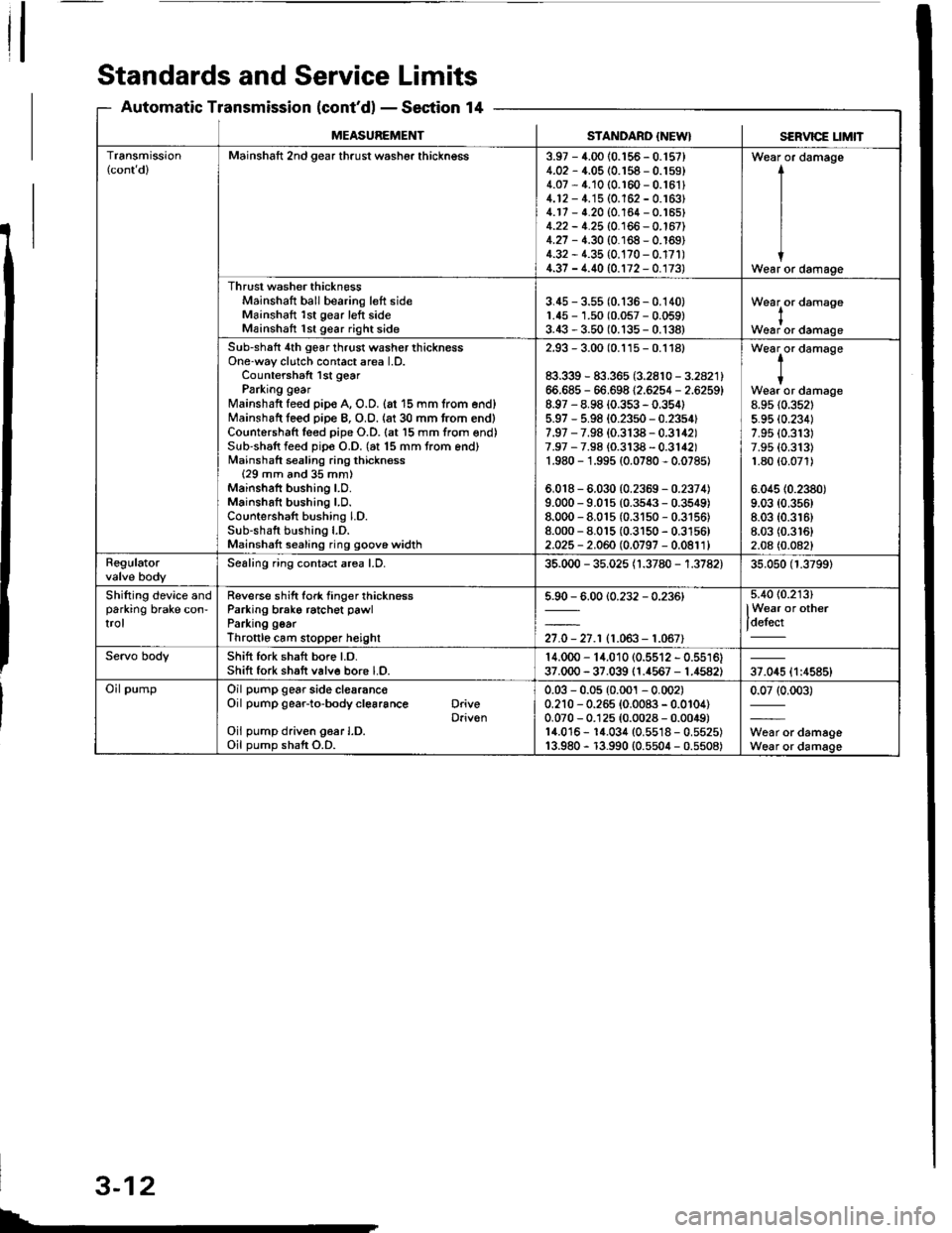
Standards and Service Limits
Automatic Transmission (cont'dl - Section 14
SERVICE t_tMtTMEASUREMENTSTANDARD {NEW}
Transmission(cont dlMainshaft 2nd gear thrust washer thickngss3.97 - 4.00 {0.156 - 0.'t57}4.02 - 4.05 (0.158 - 0.159)4.07 - 4.10 (0.r60 - 0.16114.12 - 4.'15 (0.162 - 0.163)4.17 - 4.20 (0.164 - 0.'�t65)4.22 - 4.25 (0.166 - 0.167)4.27 - 4.30 {0.168 - 0.169)4.32 - 1.35 {0.170 - 0.17r)4.37 - 4.40 (0.172 - 0.173)
Wear or damage
I
I
IWear or damage
Thrust washer thicknessMainshaft ball bearing left sideMainshaft 1st gear left sideMainshatt 1st gear right side
3.45 - 3.55 (0.136 - 0.140)1.45 - 1.50 (0.057 - 0.059)3.43 - 3.50 (0.135 - 0.138)
Wearlor damase
Woar or damage
Sub-shaft 4th gear thrust washer thicknessOne-way clutch contact area l.D.Countershaft lst gearParking gearMainshaft feed pip€ A, O.D. {at 15 mm trom end}Mainshaft leed piDe B, O.O. {at 30 mm from end)Countershaft leed pipe O.D. (at l5 mm from end)Sub-shaft feed pip€ O.D. (at 15 mm trom end)Mainshaft sealing ring thickness{29 mm and 35 mm)Mainshaft bushing LO.Mainshaft bushing LD.Countershaft bushing LD.Sub-shaft bushing l.D.Mainshatt sealing ring goove widlh
2.93 - 3.00 (0.115 - 0.1181
83.339 - 83.365 (3.2810 - 3.2821)66.685 - 66.698 12.6254 - 2.6259)8.97 - 8.98 {0.353 - 0.354)5.97 - 5.98 (0.23s0 - 0.2354f7.97 - 7.98 (0.3138 - 0.3142)7.97 - 7.98 {0.3138 - 0.3142)1.980 - 1.995 (0.0780 - 0.07851
6,018 - 6.030 (0.2359 - 0.2374)9.000 - 9.015 (0.3s43 - 0.3549)8.000 - 8.01s (0.31s0 - 0.3156)8.000 - 8.015 (0.3150 - 0.3156)2.025 - 2.060 (0.0797 - 0.0811)
t-
tWear or damage8.95 {0.352t5.95 (0.2341
7.95 (0.313)
7.9s (0.313)
1.80 {0.071)
6.045 (0.2380)
9.03 (0.356)
8.03 (0.3r6)
8.03 (0.3161
2.08 (0.0821
RegulatorSealing ring contact area LD.35.000 - 35.025 {1.3780 - 1.3782)35.050 (1.3799)
Shifting device andparking brake con-trol
Reverse shift fork tinger thicknessParking brako ratchet pawlParking goarThroftlo cam slopper heighl
5.90 - 6.00 {0.232 - 0.236)
27.0 - 27.r (1.063- 1.067)
5.4O {0.213)
lWear or other
t_'--'
Servo bodyShift fork shaft bore Lo.Shift fork shaft v6lve bore LO.14.000 - 14.010 (0.5512 - 0.5516)37.000 - 37.039 (1.{567 - 1.4582)37.045 {1:4585}
Oil pumpOil pump gear side clearanc€Oil pump gear-to-body cl€6rance DriveDriv€nOil pump driven g6ar I.D.Oil pump shaft O.D.
0.03 - 0.05 (0.001 - 0.002)0.210 - 0.265 {0.0083 - 0.0104)0.070 - 0.125 (0.0028 - 0.0049)14.016 - 1{.034 (0.5518 - 0.5525)13.980 - r3.990 {0.5504 - 0.5508)
0.07 (0.003)
W6ar or damageWear or damage
L
3-12
Page 34 of 1413
![ACURA INTEGRA 1994 Service Repair Manual Design Specifications
]TEMMETRICENGLISHNOIES
: vENSTONSOveralllength 3 DOOR
4 DOOR
Ov€rallWidth
Overall Height 3 DOOR
4 DOOR
Wheelbase 3 DOOR
4 DOOR
Track F/R
Ground Clearance
Seating Capacity
4.38 ACURA INTEGRA 1994 Service Repair Manual Design Specifications
]TEMMETRICENGLISHNOIES
: vENSTONSOveralllength 3 DOOR
4 DOOR
Ov€rallWidth
Overall Height 3 DOOR
4 DOOR
Wheelbase 3 DOOR
4 DOOR
Track F/R
Ground Clearance
Seating Capacity
4.38](/img/32/56982/w960_56982-33.png)
Design Specifications
]TEMMETRICENGLISHNOIES
:' vENSTONSOveralllength 3 DOOR
4 DOOR
Ov€rallWidth
Overall Height 3 DOOR
4 DOOR
Wheelbase 3 DOOR
4 DOOR
Track F/R
Ground Clearance
Seating Capacity
4.380 mm
4.525 mm
'1,710 mm
1,335 mm
1,370 mm
2,570 mm
2,620 mm
't,475/1,470 mm
150 mm
Four (3 DOOR)
172.1in
178.1 in
67.3 in
52.6 in
101.2 in
103.1 in
5|8.1/57.9 in
Five (4 DOOR)
,rerght (usA)cross V€hicle Weight Rating {GVWR)3,680lbs
'le,ght {CANADA)Gross Vehicls Weight Rating {GVWR)1,670 kg
:\GINEType81881 engine
818C1 engine
Cylinder Arrangement
Bore and Stroke
Displacement
Compression Ratio
81881
818C1
81881
B18C I
81881
B 18C1
81881
818C1
engrne
engane
engrne
engine
engine
engine
engine
engine
L!brication Systom
OilPump Displacement
Wster Pump Displacement
FuelRequired
81881
B18C 1
81881
B 18C1
91881
engrne
engrne
engine
engine
engine
818C1 engine
Water-cooled, 4-stroke DOHC
gasoline engine
Watercooled, 4-stroke DOHC
VTEC gasoline engine
Inline 4-cylinder, transverse
81.0 x 89.0 mm
81.0 x 87.2 mm
1,834 cm3 (mf )
1,797 cm3 (m{)
3.19 x 3.50 in
3.19 x 3.43 in
112 cu-in
110 cu-in
9.2:1
10.0 : 1
Eelt driven, OOHC 4 valve per cylinder
Belt driven, DOHC VTEC
4 valve per cylinder
Forced and wet sump, trochoid pump
50, {53 US qt, 44 lmp qt)/minute'l
71 f {75 US qt, 62 lmp qt)/minute"
140 f (148 US qt, 123 lmp qt)/minute*!
140 f (148 US qt. 123 lmp qt)/minute*'
UNLEADED gasoline with 86 Pump
Octane Numb€r or higher
Premium UNLEADED gasoline wilh
91 Pump Octane Number or higher
STARTERTypo
NormalOutput
NominalVoltage
Hour Rating
Direction of Rotation
Weight
Gear reduction
1.4 kW
12V
30 seconds
Clockwise as viewed lrom g6ar end
3.7 k9 | 8.3lbs
CLUTCHClutch Type
Clutch Facing Area
M/TSingle plate dry, diaphragm spring
Torq!e converter
203 cm'� I 31 sq-in
TRANSMISSIONTransmission Type M/T
Primary Reduction
Synchronized 5-speed forward, 1 reverse
Electronically controlled
4-speed automatic. 1 rcverse
Diract 1 : 1
'1: At 6,000 engine
'2: At 7,600 engine
rpm
rpm
(cont'd)
3-17
Page 35 of 1413
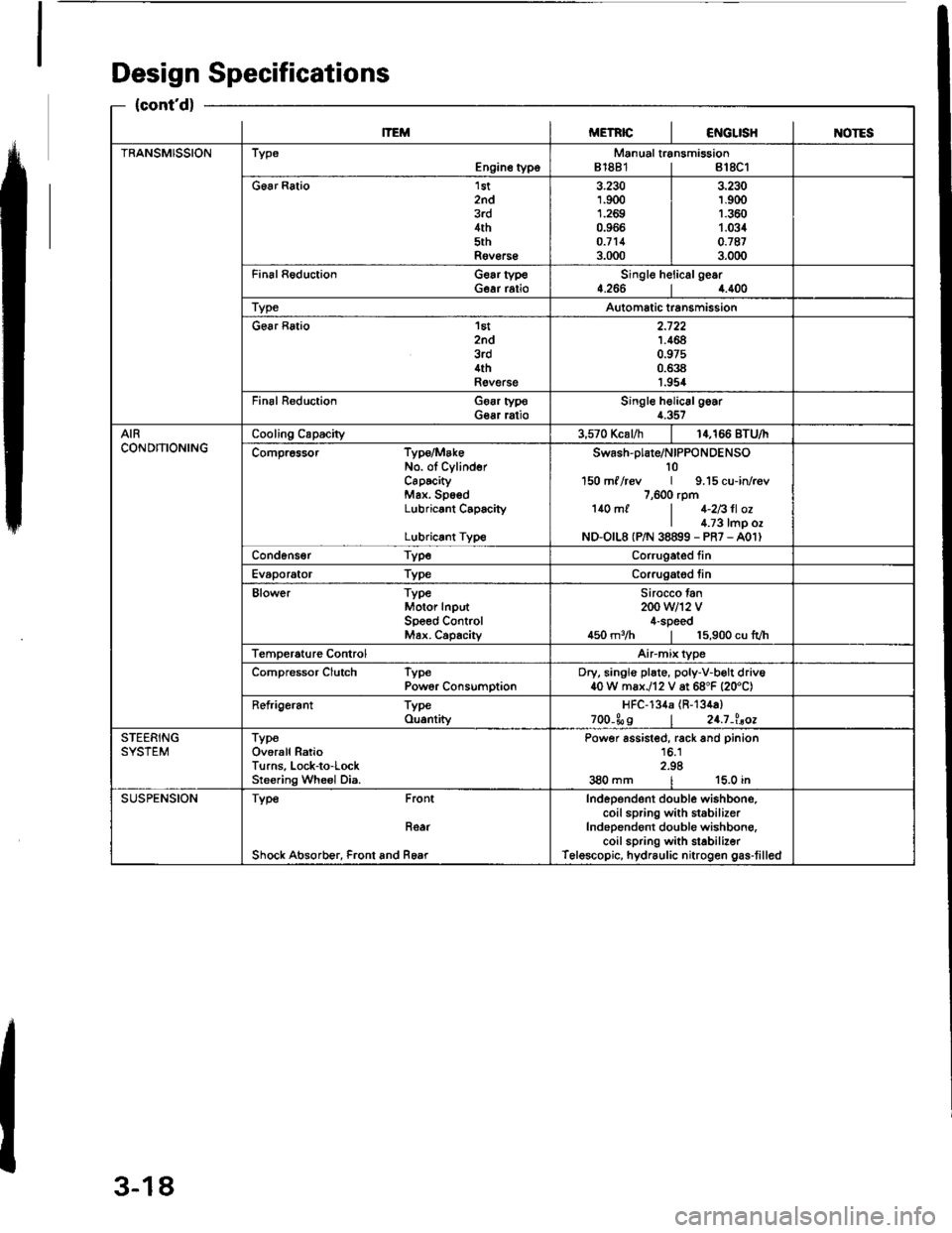
Design Specifications
{cont'd}
lTEMMETRICI€iIGLISHINOTES
TRANSMISSIONTypeEngine typoManual transmission81881 | 818C1
G6ar Ratio 1st2nd3rd4th5thRov€rs€
3.2301.9001.2690.966o.7113.000
3.230r.9(X)1.3601.0340.'t873.000
Fin6l Reduction Gear typeGear ratioSingle helicalge.r4.2664.400
TypeAutomatic transmission
Gear Ratio 'l6t
znd3rd4thRevelse
2.7221.4640.97s0.6381.954
Final R€duction Goar typoGear ratioSingle helic6lgoar4.357
AIRCONDITIONINGCooling Capacity3,570 Kcal/h14,166 BTU/I
Compr6ssor Type/MakeNo. ol CylinderCaPtcityMax. SpsedLubricant C6pacity
Lubricrnt Type
swash-plare/NIPPoNDENSO10150 ml /rcv | 9.15 cu-in/r€v7,600 rpm140 mf | 1-2Bll ozI l.;3 tmp ozND-O|L8 (P/N 38899 - PR7 - A01)
Cond6ns€r TypeCorrugated fin
Evaporator TypeCorrugatod tin
Blower TypeMotor InputSpeed ControMax. Capachy
Sirocco tan200 w12 v4-speed450 m3/h | 15,900 cu lvh
Temperature ControlAirmix type
Compressor Clutch TypePowor ConsumptionDry, singlo plate, poly-V-b€lt driv640 W max./12 V at 68"F {20'C)
Refrigerant TypeOu.ntityHFC-134a (R-134a)
zoo-Ss I 24.7-l.aoe
STEERINGSYSTEMTypeOverall RatioTurns, Lock-to-LockSreering Wheel Dia.
Power assisted, rack and pinion16.12.98380 mm | 15.0 in
SUSPENSIONType Front
Roar
Shock Absorb€r, Front and Rear
Independent double wishbono,coil spring with st6bilizerIndependont double wishbong.coil spring with stabilizerTelescopic, hydraulic nitrogen gas-tilled
3-18
Page 40 of 1413
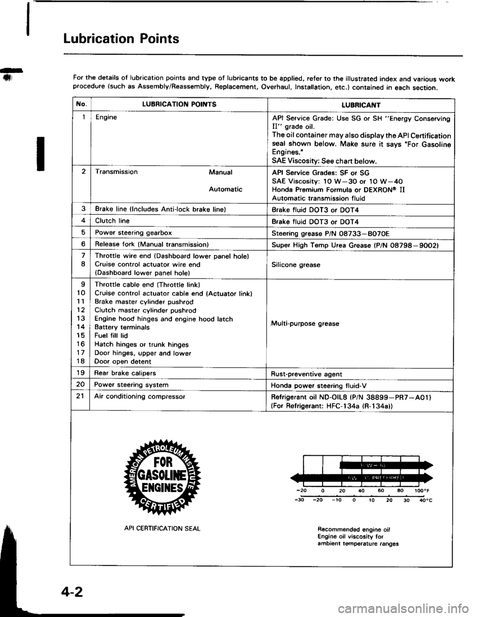
Lubrication Points
For the details ol lubrication points and type of lubricants to be spplied, reter to the illustrated index and various workprocedure (such as Assembly/Reassembly, Replacement, Overhaul, Instatlation, etc.) contained in each section.
No.LUBRICATION POII\ITSLUBRICAI\IT
IEngineAPI Service Grade: Use SG or SH "Energy Conserving
II" grade oil.
The oil container may also display the API Certifications€al shown below. Make sure it says'For GasolineEngines.'
SAE Viscosity; See chan below.
Transmission Manual
Automatic
API Service Grades: SF or SG
SAE Viscosity: 1O W-3O or 1O W-4O
Honda Premium Formula or DEXRON@ II
Automatic transmission fluid
3Brake line (lncludes Anti-lock brake linelBrake fluid DOT3 or DOT4
4Clutch lineBfake tluid DOT3 or DOT4
Power steering gearboxSteoring grease P/N 08733-BO7OE
Release fork (Manual transmission)Supe. High Temp Urea Grease (P/N O8798*9OO2)
8
Throttle wire end {Dashboard lower Danel holel
C.uise cont.ol actuatot wire end
{Dashboard lower Danel holel
Silicone grease
I
10'I '�l
12
13
14
15
to
17
18
Throttle cable end (Throttle linkl
Cruise control actuator cable end lActuator link)
Brake master cvlinder Dushrod
Clutch master cylinder pushrod
Engine hood hinges and engine hood latch
Batte.v terminals
Fuel fill lid
Hatch hinges or trunk hinges
Door hinges. upper and lowet
Door oDen detent
.Multi-purpose grease
19Rear brake calioersRust-p,eventive agant
20Power steering systemHonda power steering tluid-V
21Air conditioning compressorRetrigerant oit ND-otL8 |PlN 38899-pR7-A01)(For Relrigerant: HFC-134a (R-134a))
-20 0 20 r}() 60 ao loooF
-30 -20 -'to o 10 20 30 40"c
Recolnmendod engine oilEngine oil viscosity torambient tgmpelalure rangos
API CERTIFICATION SEAL
Page 52 of 1413
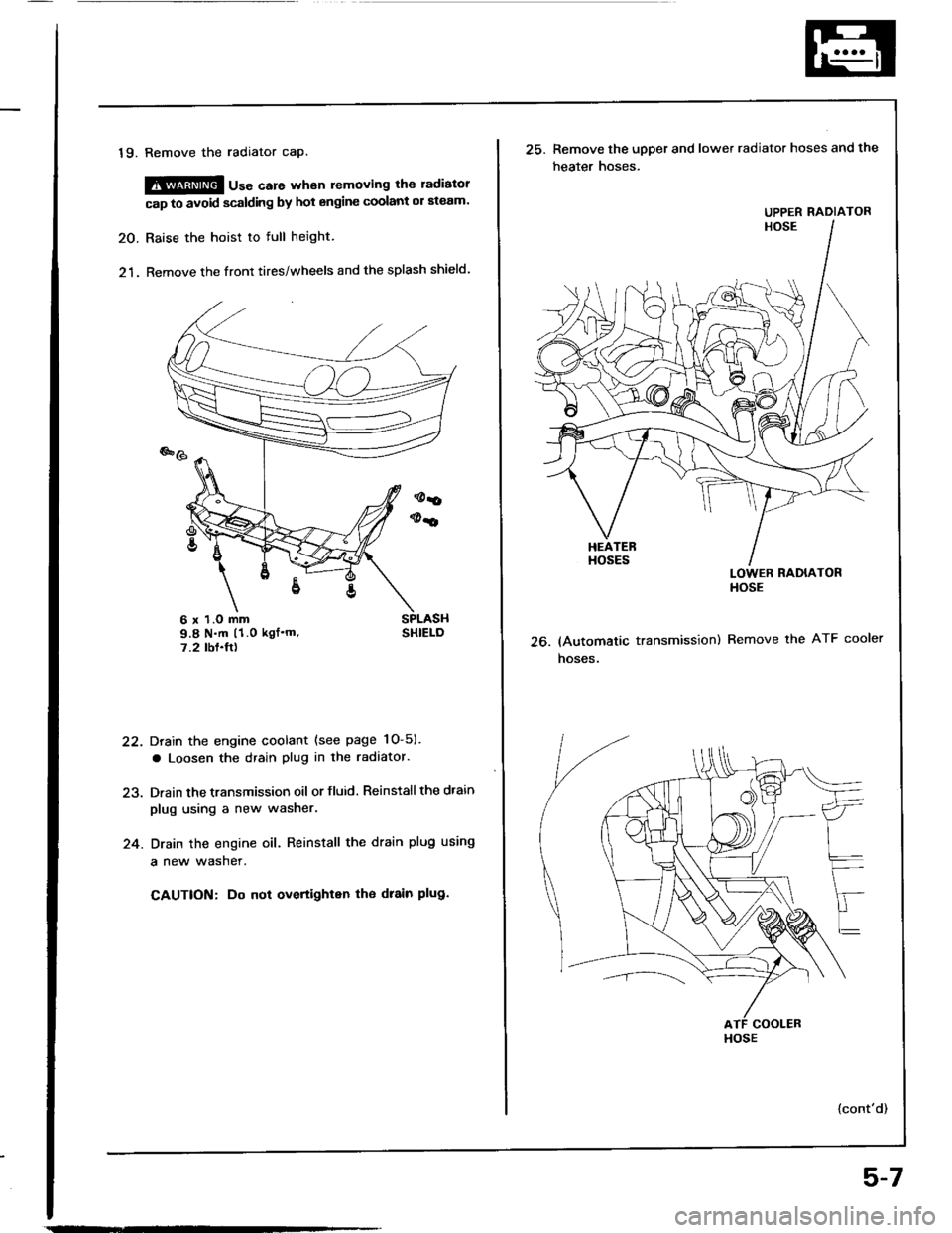
19. Remove the radiator cap.
@@ u"" care whan removing the ladiatol
cap to avoid scalding by hot engine coolant ol ateam.
20. Raise the hoist to full height.
21. Remove the front tires/wheels and the splash shield.
Drain the engine coolant (see page 1O-5).
a Loosen the drain plug in the radaator.
Drain the transmission oil or fluid. Reinstall the dtain
plug using a new washer.
Drain the engine oil. Reinstall the drain plug using
a new wasner.
CAUTION: Do not overtighten tho drain plug.
22.
24.
6 x 1.O mm9.8 N.m (1.0 kgf'm'7.2 tbf.ft)26.
25. Remove the upper and lower radiator hoses and the
heater hoses.
LOWER RADIATORHOSE
(Automatic transmission) Remove the ATF cooler
hoses.
{cont'd)
UPPER RADIATOR
HOSE
5-7
Page 143 of 1413
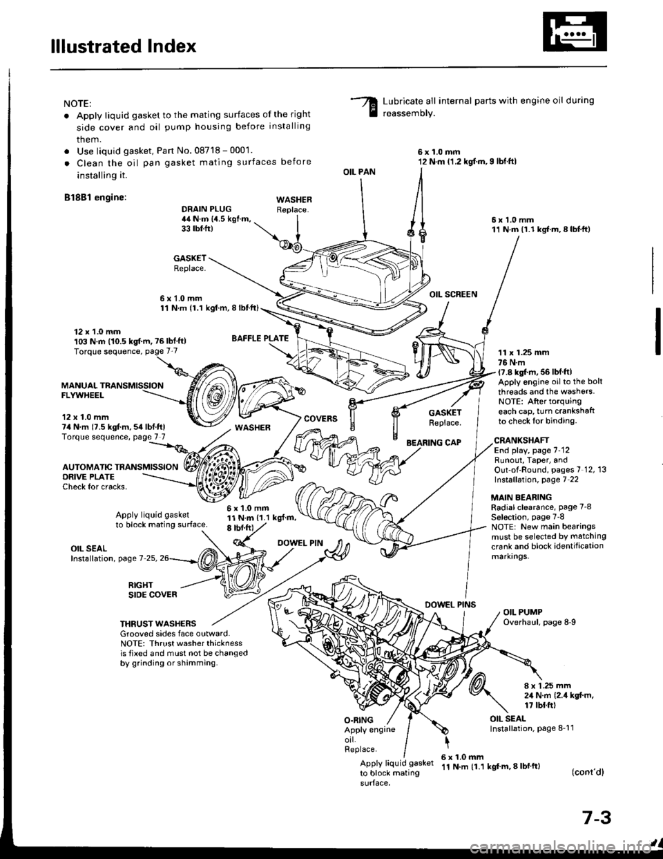
lllustrated Index
NOTE:
. Apply liquid gasket to the mating surfaces of the right
side cover and oil pump housing before installing
them.
. Use liquid gasket, Pan No.08718 - 0001.
. Clean the oil pan gasket mating surfaces before
installing it.
Bl8Bl engine: wAsHEF
Lubricate all internal parts with engine oil during
reassemory.
6x1.0mm12 N.m (1.2 kgf.m,I lbf.ftl
6x1.0mm11 N.m (1.1 kgf.m,8lbtft)
OIL SCREEN
11 x 1.25 mm76 N.m17.8 kgl.m, 56 lbf ftlApply engine oilto the bolt
threads and the washers.NOTE: After torquingeach cap, turn crankshaftto check lor binding.
DRAIN PLUG44 N.m {4.5 kgf.m,33 tbtfr)
GASKETReplace.
6x1.0mm1'l N.m {1.1 kgt.m, I lbtft)
OIL PAN
O.RING
GASKETReplace.
BEARING CAP
12 x 1.0 mm103 N.m (10.5 kgf.m, ?6lbf ft)
MANUALFLYWHEEL
'12 x 1.0 mm74 N.m {7.5 kgt m,54lbf.ftlTorque sequence, page 7 7
DRIVE PLATECheck for cracks,
AUTOMATIC TRANSMISSION
WASHER
6x1.0mm11 N.m {1.1 kgl.m,8 tbf.frt
CRANKSHAFTEnd play, page 7-12Runout, Taper, andOut-of-Round, pages 7 12, 13Instsllation, page 7 22
MAIN BEARINGRadial clearance, page 7-8
Sel€ction, page 7-8NOTE: New main bearingsmust be selected by matching
crank and block identificationmarkrngs.
Apply liquid gasket
to block mating surface.
OIL SEALInstallation, page 7-25,
RIGHTSIDE COVERDOWEL PINSOIL PUMPOverhaul, page 8-9THRUST WASHERSGrooved sides face outward.NOTE: Thrust washer thicknessis tixed and must not be changedby grinding or shamming.
8 x 1 .25 mm2,1 N.m {2.4 kgt m,17 tbt.ft)
OIL SEALInstallation, page 8-11Apply engrneorl.Replace.
Apply liquid gasket
to block mating
6x1.0mm'11 N.m {1.1 kgf'm, 8 lbl ft)(conr'dl
7-3
Page 345 of 1413
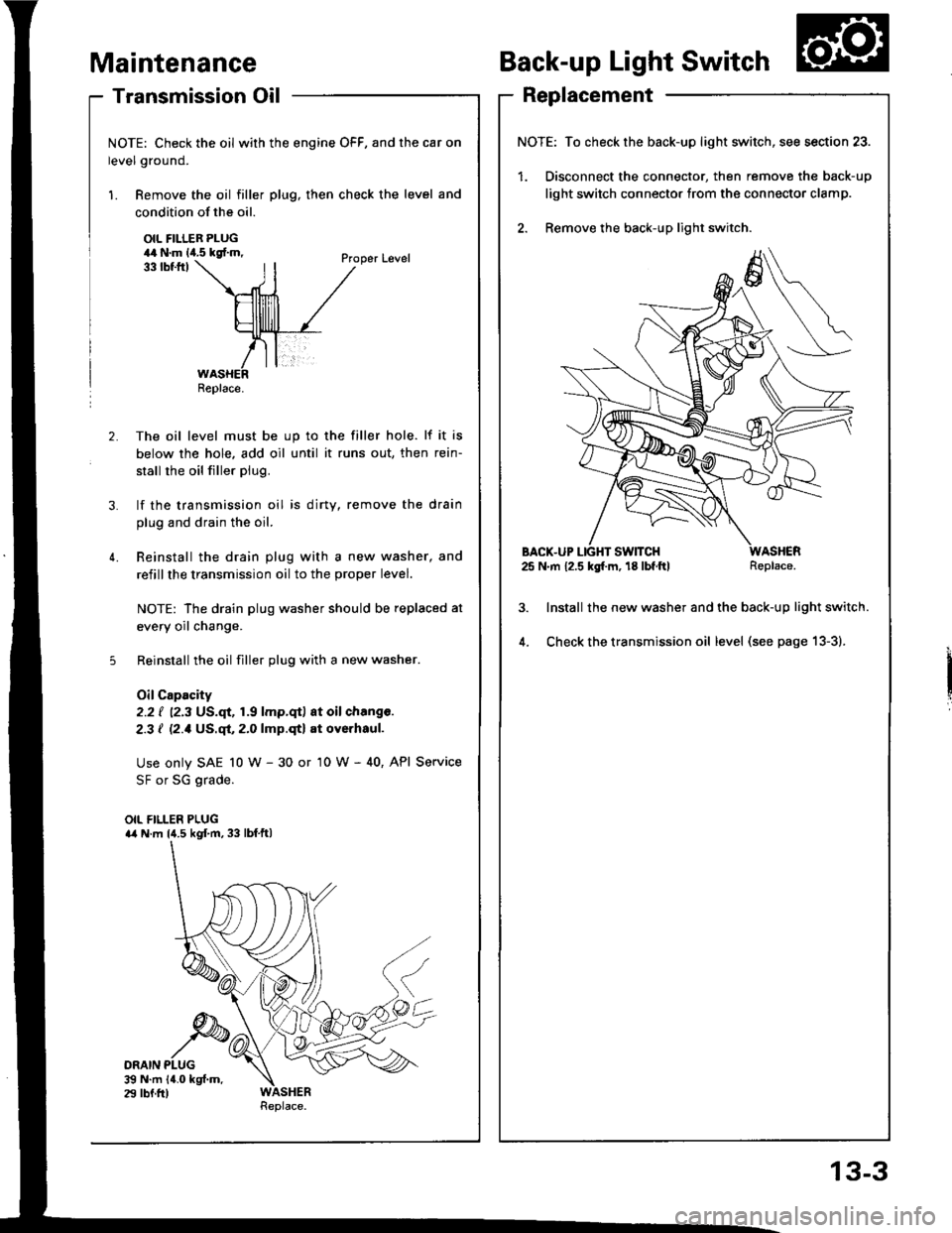
- Transmission Oil
NOTE: Check the oil with the engine OFF, and the car on
level ground.
1. Remove the oil filler plug, then check the level and
Maintenance
condition of the oil.
OIL FILLER PLUG44 N.m lia.5 kgf.m,
ORAIN PLUG$ N.m 14.0 kgf.m.29 lbf.fr)
33 tbtftlProper Level
2. The oil level must be up to the filler hole. lf it is
below the hole. add oil until it runs out, then rein-
stall rhe oil filler plug.
3. lf the transmission oil is dirty, remove the drain
plug and drain the oil.
4. Reinstall the drain plug with a new washer, and
refillthe transmission oil to the proper level.
NOTE: The drain plug washer should be replaced at
every oil change.
5 Reinstall the oil filler plug with a new washer.
OilCapacity
2.2 ( ''2.3 US.qt,1.9 lmp.qt) at oil chang€.
2-3 I l2.1Us.ql,2.0lmp.qtl at oyerhaul.
Use only SAE 10 w - 30 or '10 W - 40, API Service
SF or SG grade.
OIL FILLER PLUGa4 N.m l{.5 kgf.m, 33 lbf.ftl
Back-up Light Switch
Replacement
NOTE: To check the back-up light switch,
1. Disconnect the connector, then rem(
light switch connector trom the conn
2. Remove the back-up light switch.
BACX-UP LIGHT SWITCH25 N.m 12.5 kg[.m, 18 lbf.ftl
lnstall the new washer and the back-
Check the transmission oil level (see
Replace.
/itch, see section 23.
remove the back-up
]onnector clamp.
-up light switch.
) page 13-3).
Replace.
13-3
Page 346 of 1413

Transmission Assembly
Removal
Mskc aurs iack! and safoty Etands aro placod proper-
ly lsl8 saqtion 1|.
Apply parking brake tnd block rear whccl! to car
will not roll ofl stand3 and f.ll on you while wotking
undrr it.
CAUTION: Use tondcr coyar3. to avoid drmlging
plintsd 3qrfaca3,
Disconn€ct the negative {-) cable from the battery,
then the positive (+) cable.
Drain the transmission oil, then reinstall the drain
plug with a new washer (see page 13-3),
Remove the intake air duct and the air cleaner hous-
ing assembly,
AIR CITANERHOUSING
13-4
4. Disconnect the back-up light switch connoctor and
the transmission ground wir€.
5, Remove the lower radiator hose clamp trom ths
transmission hanger B.
BACK.UP LGHTsuTcH cot{t{EcToR
lnaNsMttistoNGROUND WIRE
tnaNsi ssloNHANGEB B
o.
1.
R€move the wire harness clamPs.
Disconnect the stsrt€r motor cables and the vahicla
soeed sensor (VSS) connector.
VSS OONNECTOR
Page 350 of 1413
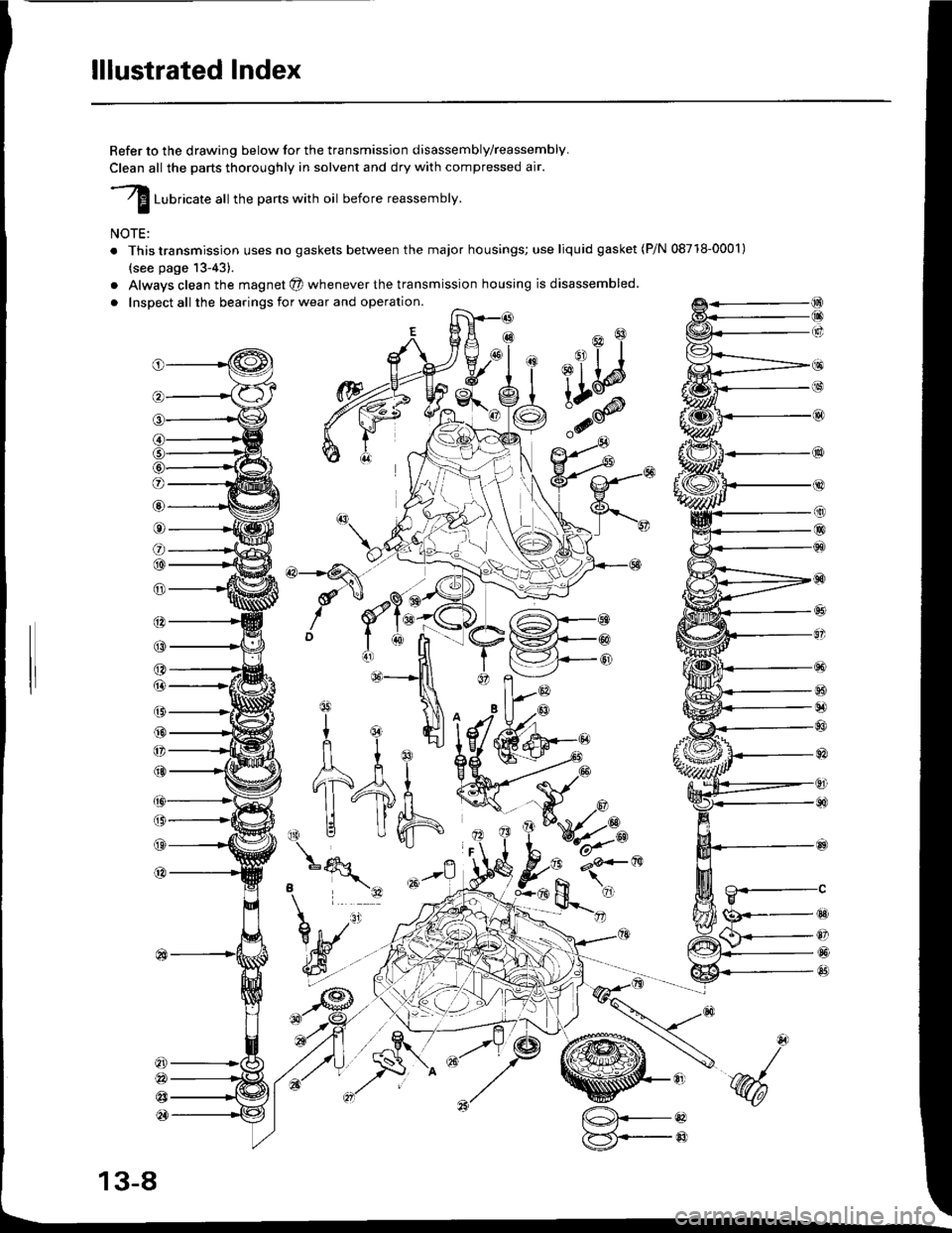
lllustrated Index
Refer to the drawing below for the transmission disassembly/reassembly.
Clean all the parts thoroughly in solvent and dry with compressed air.
I ruurlcate att the parts with oil before reassembly.
NOTE:
. This transmission uses no gaskets between the major housings; use liquid gasket (P/N 08718-0001)
{see page 13-43).
a
a
Alwavs clean the magnet @ whenever the transmission housing is disassembled.
Inspect all the bearings for wear and operation.
(9
@
@
tqqlnl^'1ult I Ej
nl
11-4fi
,\|j Uh
o
@
o
@@
@
@
(3
(,
@
@
@
a
@
@
@
@
B
tg
Y
o
@
@
@
*N
13-8
[@.--oaF5i,--@:7