engine ACURA INTEGRA 1994 Service Repair Manual
[x] Cancel search | Manufacturer: ACURA, Model Year: 1994, Model line: INTEGRA, Model: ACURA INTEGRA 1994Pages: 1413, PDF Size: 37.94 MB
Page 235 of 1413

Th. ll.lfunction Indicltor Lamp
lMlll at!y3 on o. cornaa on alt6ltwo aacond!.
Connect the SCS short connectorto th6 sorvice check connector(see page 11-34).
Turn the ignition switch ON.
Go to iolfdiagnostic Proceduros(se€ pago 11-34).Does the MIL indicate anv Oi-agnostic Trouble Code (DTC)?
Romove th€ SCS shon connectorlrom the service ch€ck connector.
Turn the ignition switch OFF.
Try to start the engine.
Connect the test harness betweenthe ECM and connectors (see
page 11-37).
Turn the ignition switch ON.
Measure voltage botween D4 (+ )terminal and D22 { - ) terminal.
connect the SCS shonconnector to servlcecheck connector.ls there approx. 5 V?
Ropair shon to body g.ound inBRN/WHT wire betwoon th6 ECMlD4) end sorvlco chock connocto?.Measure voltage be_tween D4 {+} terminaland body ground.
- R6pair open in BRN/WHT witobotwoon EcM lD4) and s6rv-ice chock connactor.- Repoir opon in BLK wiro bo-twoon 36rvi@ chock connectoaand G4Ol.
ls there approx. 5 V?
InsDoct ECU {ECM) 115 A) tuse inth6 undeFhood luse/relav box.
- Rsolaco ECU {ECM} (15 Allus€.- R6pair shon in YEL/WHT wilobotw6on ECU lEcMl 115 A)fuso and PGM-FI main rolay.
Remove the scs shortConnector from theservice check con-nector.
ls the luss OK?
NOTE:
a When there is no code stored, the MIL willstay on if the service check con-
nector is shorted.
a tf this svmotom is intermittent, check for:
- A loose ECM fuse (15A) in the under-hood tuse/relay box
- A loose No. 24 fuse (ACG) (ALT) ( 1 5A: B1 8B 1 engine, 2OA: B18C 1 en-
gine) in the under-dash fuse/relay box- An intermittent short in the BRN/WHT wire between the ECM (D4) and
the service check connector- An intermittent oDen in the BLK wire between the service check con-
nector and G4O1- An intermittent shon in the GRN/ORN wire between the ECM (A 13) and
the gauge assembly.- An intermittent short in the YELMHT wire between the ECM (D19) and
the MAP sensor- An intermittent short in the YEL/BLU wire between the ECM (D20) and
the TP sensor
o ooooo ooo ooo o loooooooo liii:$A$.Ps,l o oo ooo ooooo
o oooo ooo o o ooo I oooooooooooooooooo
D4 (+)
l"oo,o'.
D22 t-l
uu,l
'NOTE: After repair, disconnect the SCS ShortConnsctor, test drive the car, and recheckthe MIL
lor a code.
(cont'd)
(To page 1 'l -44)lTo page 1 1-44)
11-43
Page 236 of 1413

(From page 1 1-43)
Inspect the No. 24ACG {ALT) (lG)(15 A: 81881 engine, 2OA:818C1 enginel fuse in the under-dash fuse/relav box.
- R.pllr .hon in BLK|rEL wlr6batr.v€qr undariair luro/Fbybox lnd FGM-FI m.in .obv.- noebco lto. 24 ACG {lG) nLT)(15 A: 81881 ongin., 2OA:Bl8Cl onein.l tu!6.
ls the fuse OK?
Turn the ignition switch ON.
Disconnect the 3P connector oteach sensor one al a time:. MAP sensor. TP sensor
Rcplaoo thg lgnlor that caur6dth. llght to Oo out.Does the MIL remain ON?
Turn the ignition switch OFF.
connect the test harness.Disconnect the "D" connectorfrom th€ ECM only, not the mainwire harness (see page 11-37).
Check tor continuity betweenbody ground and D19, O2O ter-minals,
- Bapai? rhod ro body g.ound inYEL/WHT wi.e boiwoon ECM(Dl9) .nd MAP ..n3or.- R.p!k shon to body ground inYEL/BLU wire b.lwo6n ECM(O2Ol .nd TP 3on!or.
Reconnect all tho sensor con-necrors,Reconnect the "D" connector torhe ECM.
Turn the ignition switch ON.
{To page 11-45}
System
Control Module (ECMI (cont'dl
PGM-FI
Engine
Dt9I
I oooooooooo ooo I oooooooo I omoool o oooooooooo | |I ooooooooooooo I oooooooo 1o('oe(lo I ooooooooooo | |-lD2O I
\-.J
Continuity?
(From page 11-43)
Disconnect "A" con-nector from the ECM.
Subrtltute r knowngood ECM.nd rochock. ll lymptom/indics-tlon g@a rw!y, rephco tho origi-n.l ECM.
ls the MIL ON?
Ropair short to bodygiound in GRN/ORNwir6 botwoon tho ECMlA131 6nd MlL.
11-44
Page 238 of 1413

PGM-FI System
Heated Oxygen Sensor lHO2Sl
ztRcot{lAELEiIE'{T
HEATER
- --.'!- - -__-
lrPl _l !l-
-fi-l: The Malfunction Indicator Lamp (MlL) indicates Diagnostic Troubls Code (DTC) 1: A problsm in
/? the Heated Oxygen Sonsor (HO2S| circuit.
The Heated Oxygen Sensor IHO2S) det€cts th6 oxygon contont in th6 exhaust gas and signals th6 ECM. In operation,
the ECM receiv€s th6 signals trom the sensor and vari€s the duration during which tu6l is iniocted. To stabilize thd sen-aor's output, tho sensor has 8n intarnal heater and the sensor olemant is coatod with a catslyst. The HO2S is installod
in TWC housing (B18Cl engine) or exhaust pipe B (Bl8Bl €ngine).
sEl{SORTERMII{ALS
:tz-t6l-/ --.- \
VOLTAGE (V}sTotcHtoltETncAIR-FUEL BANO
HEATEBTEBMIT{ALSRICH - AN. - LEAI{FUELRATIO- Th! mll h.. bo.n raportad on.- Wlth thr SCS rhon coon cto.connoctad lr.. p!9. 1t-341,cod. t l. Indlcltrd.
Oo th€ ECM Res€t Procodure {soopag€ 11-35).
Stan the 6ngine. Hold th6 engine
A3,qgq rpm with no load {A/T in
Lryl or lll position, M/T in nourralluntil the radiator lan com6s on.then lot it idle lor ot least on6minutg beforo road t€6tin0.
Connoct ths SCS short connoctorto th6 sorvic€ check connectorlsoo p.g6 1 1-34).
Rood t€st witlthe automatictransmission in L?l position (M/T:4th gear).Stsrting st l,600 rpm, acc6lorateu6ing wide open throttlo for atlesgt 5 seconds. Thsn dgcol€rstefor at lorst 5 s€conds with th€throttlo completoly closed.
Intarmittd[ t llurc, lyri.m b Of!l thla tlmc. Ch.ck lor poor con-nacdona o? loota wlrat |l C223(loc.trd at right $ock towo.l,Cr 13 (HO2S| lnd ECM.
Ooes the MIL blink and doos itindic6t6 cod6 1?
Go to plga and partonn tad fotcod. 43 lr.a p.go l1-501.
1 1-46
Page 242 of 1413

PGM-FI System
rj-t
--t-.
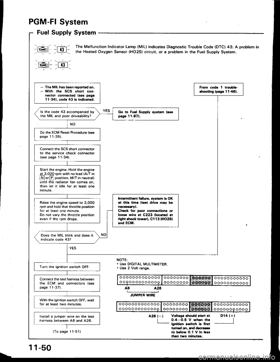
Fuel Supply System
-+-lt@t- -t 13 |- ' "- - --i--
T,-n The Maltunction Indicator Lamp (MlL) indicares Diagnostic Trouble Code (DTC) 43: A problem in
- L:!-i - the Heated Oxygen Sensor (HO2S) circuit. or a probtem in the Fuel Supply System.
NOTE:. Use DIGITAL MULTIMETER.. U6e 2 Volt rang6.
o oooooo oooooo I oo oooooooooooooooooooQoo ooo ooooo I oooo ooooooooooooooo
426
JUMPER WIRE
o ooooo oooo ooo I oo oooooo Isdtcllodsl ooo ooooooooo oooo ooo oo ooo I oooo ooooooooooooooo
D14 {+l
I
426 t-l vohrgo rhould rl.n.t
| 0.4-0.5 V wh.n th..- ignirioo .wilch i! firdt|rtrod o.r, Itd docr!6ato b.low O.1 V in L..th6n two minutaa.
- Tho MIL h.s boen reportod on.- With rhe SCS short con-noctor connocted (soo paga1l-34), codo 43 b indlcat.d,
From codr I troebl.-lhoorlng lprgo 1146).
ls the code 43 accompanied bythe MIL and poor driveability?Go to Fuol Supply .y.t.m (|ecpag6 1t-971.
Do the ECM Reset ftocedure lseepage 11-35).
Connect the SCS short connectorto the service check connector{see page 'l1-34).
Start the engine. Hold the engineat 3,00O rDm with no load {A/T in
@or@ position, M/T in neutral)until the radiator Ian comes on,then let it idle for at least onemanute,
Intonnitl.nt t llure, tydom lr OKat thi. tim. lto.t drlv. mly b.nocaararyr.Chock lor poo? connactlona otloots wiro at C223 lloc.t.d atrlghl lhock towo.]. Cl13lHO2Sland ECM,
Raise the engine speed to 3,000rpm and hold that throttle positiontor at least one minute.Do not vary the throttle positioneven if the rpm drops.
Ooes the MIL blink and does itindicate code 43?
Turn the ignition swilch OFF.
Connect the test harness betweenthe ECM and conneclors {seepage 1 1-371.
With the ignition switch OFF, waitfor at least two minutes.
lnstall a jumper wire on the testharness between A6 and A26.
11-50
1To page 1 1-5'l l
Page 245 of 1413

Measure voltage between YEL/WHT {818C1 engine), YEL/RED(B188'1 engine) {+ ) terminal andbodv ground.
Measure voltage between YEL/WHT (818C1 engine), YEL/RED{B1881 engine) (+ } terminal andGRN/WHT (- ) terminal.
ls there approx. 5 V?
Repair opon in GRN/WHT wir6 botweonECM lD2l l and thoMAP sonsor,
Turn the ionition switch OFF.
ls there approi. 5 V?
Connect the test harness "D"
connector to the ECM only, nottothe main wire harness {see page11,37).
Turn the ignition switch ON.
Measure voltage betweon wHT/YEL (+ ) terminal and GRN/WHT{- } terminal.Measure voltage between D19{+} terminal and D21 {-}termrnat,
ls there approx. 5 V?
Bepair open in YEL/WHT wi.e be-tw€6n ECM lD19) and tho MAPaon30t.
ls there approx. 5 V?
Substitule s known-good ECMand rechock. ll symptom/indica'tion goes away, replac€ tho oiigi'nal ECM.Turn the ignition switch OFF.
Reconnecl the 3P connector tothe MAP sensor.
Connect the test harness betweenthe ECM and connector (see page1 1-371.
Turn the ignition switch ON.
11,52)
{To page 11-54}lTo page I l-54)
(cont'd)
Page 247 of 1413
![ACURA INTEGRA 1994 Service Repair Manual PGM-FI System
TDC/CKP/CYP Sensor
_f=l_ fi_l The Malfunction Indicator Lamp (MlL) indicates Diagnostic Trouble Code (DTC) 4: A problem int:- the Crankshaft Position (CKP) Sensor circuir.
l6]- ftl - T ACURA INTEGRA 1994 Service Repair Manual PGM-FI System
TDC/CKP/CYP Sensor
_f=l_ fi_l The Malfunction Indicator Lamp (MlL) indicates Diagnostic Trouble Code (DTC) 4: A problem int:- the Crankshaft Position (CKP) Sensor circuir.
l6]- ftl - T](/img/32/56982/w960_56982-246.png)
PGM-FI System
TDC/CKP/CYP Sensor
_f'=l_ fi_l The Malfunction Indicator Lamp (MlL) indicates Diagnostic Trouble Code (DTC) 4: A problem int:- the Crankshaft Position (CKP) Sensor circuir.
l'6]- ftl - The Malfunction Indicator Lamp (MlL) indicates Diagnostic Trouble Code (DTC) 8: A problem in-i- the ToD Dead Center ITDC) Sensor circuit.
-flG]l- ft-] The Malfunction Indicator Lamp (MlL) indicates Diagnostic Trouble Code (DTC) 9: A problem in- , - the Cvlinder Position ICYP) Sensor circuit.
The CKP Sensor determines timing tor fuel injection and ignition of each cylinder and also detects engine speed. TheTDC Sensor determines ignition timing at start-up (cranking) and when crank angle is abnormal. The CYP Sensor detects
the position of No. 1 cylinder tor sequential fudl injection to each cylinder.
- \.--r-l - -__l_-
tPJ:;LlJ:lEl--;l ?,:
- Tho MIL hos beon roponod on.- With rho SCS short connoctorconneclod lsso pago I l-341,code 4, 8 and/or 9 ar6 in-dicated.
Do the ECM Reset procedure (seepage 11-35).
Intohittent failuro, syst€m is OKat thia tima {t6st drivo may benoceaSaayr.Chock for poo. connections orlooss wires at C222 (located atright shock towerl, C110(TOC/CKP/CYP Sonsorl and ECM.
ls the MiL on and does it in-dicate code 4, 8 and/or 9?
Turn the ignition switch OFF.
Disconnect the 8P connector fromthe TDC/CKP/CYP sensor.
{To page 1 1-57)
11-56
Page 249 of 1413

PGM-FI System
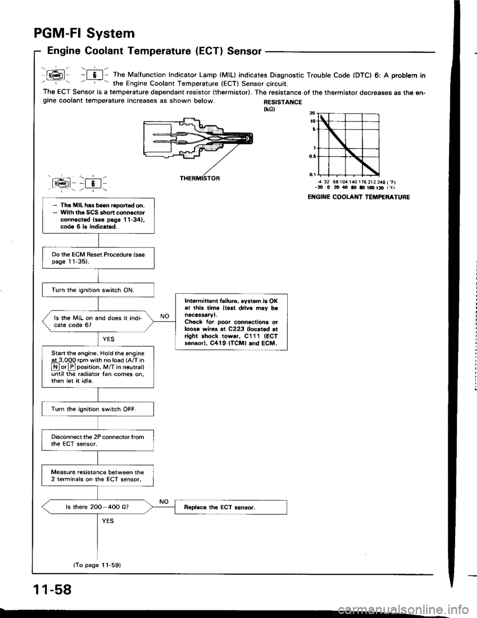
Engine Coolant Temperature (ECT) Sensor
- ,-!-- ---1- -
t@l- -l 6 | The Malfunction Indicator Lamp (MlL) indicates Diagnostic Trouble Code (DTC) 6: A problem in- - the Engine Coolant Temperature (ECT) Sensor circuit.The ECT Sensor is a temperature dependant resistor (thermistor). The resistance oI the thermistor decreases as th€ en-gine coolant tempe.ature increases as shown below.
J rsG-11
RESISTANCE{k0l
- \.--r-l--t 5 | /--i- \
j 32 68lOrr la0 t76 2t2 2a8 (.Fl-2tt 0 20 rto ao D r@ t20 (,cl
ENGII{E COOLAI{T TCMPERATURE- Th€ MIL has boon roDortod on.- Wlth tho SCS shon connoctorconnoctod {s66 pag6 '11-34},
code 6 is indicatod.
Do the ECM Reset Procedu.e lseepage 1 1-35).
Turn the ignition switch ON.
Intoimittont failur6. ryatom is OKel this lime ltosl d.ive may bonocassaryl.Chock for poor connsctiona orlooso wiros al C223 {locatod attight shock lowor, C111 (ECT
sonsorl, C419 {TCMI and ECM.
ls the MIL on and does it indi-cate code 6?
Start the engine. Hold the engineat 3,O0O rom with no load {Afi in
N or lF]position, M/T in neutral)until the radiator lan comes on,then lot it idle.
Turn the ignition swirch OFF.
Disconnect the 2P conneclor lromthe ECT sensor.
Measure resistance between the2 terminals on the ECT sensor.
ls there 2OO-4OO O?
(To page 1 1-59)
11-58
--
Page 260 of 1413
![ACURA INTEGRA 1994 Service Repair Manual PGM-FI System
Electrical Load Detector (ELDI
tft;-]/ The Maltunction Indicaror Lamp (MlL) indicatss Diagnostic Trouble Code IDTC) 20: A probtem in-Li!- tne Electrical Load Detecror {ELD} circuit.
With ACURA INTEGRA 1994 Service Repair Manual PGM-FI System
Electrical Load Detector (ELDI
tft;-]/ The Maltunction Indicaror Lamp (MlL) indicatss Diagnostic Trouble Code IDTC) 20: A probtem in-Li!- tne Electrical Load Detecror {ELD} circuit.
With](/img/32/56982/w960_56982-259.png)
PGM-FI System
Electrical Load Detector (ELDI
tft;-]/ The Maltunction Indicaror Lamp (MlL) indicatss Diagnostic Trouble Code IDTC) 20: A probtem in-Li!- tne Electrical Load Detecror {ELD} circuit.
With lho SCS lhon connectolconnoctod {ree pago 11-34}, cod.20 is indicatod.
Do the ECM B6set Procedurs {seepage 1 'l-35).
Start engine and keep engin€speed at idle.Turn on headlights.
lntennlna tlllure, lyrtom lt Ol(!t irl. dm. (lgtt driv. mly [email protected] for Door connactlona oaloota wiro. rt C218 IELD, lndEctrt.
Ooes the MIL indicato code 20?
Romove the undgr-hood fusg/relay box and remove the tus6/relav box lowet cover.
Turn lhe ignition switch ON.
Measure voltage betw€on BLK/YEL (+l terminal and BLK (-)terminal.
Msasuro voltag€ b€tweon BLK/Y€L {+) terminal snd bodvground.ls there bartory voltagel
Rcpir oo.n in BLK wir.batwaan lha 3P connrc-tor lnd G2Ol {loc.t.dtroit ot angh|. comprn-m.r dghl .ld.l,
B.p.lr op.n in BLKrYEL wlrr b.-tw..n o.24ACG (ALn flcl115A: Bl88l .ngln!, 20 A:818C1cnginol fu!. In thr und.r{..htu.o/r.lly bor lnd tho 3P con-rcclo?.
View tromwire side
BLK (-)
(To page 11-7'l)
GRn/iED I - |
BLK/YEL I + I
11-70
Page 263 of 1413

PGM-FI System
Knock Sensor (KS) tB18C1 enginel
ml- nl: The Malfunction Indicator Lamp (MlL) indicates Diagnostic Troubte Code (DTC) 23: A probtem inthe Knock Sensor (KS) circuit.
a6l--fzt.i--1/.---r+\
ware sido
o ooooo ooo ooo o looooooooo oooo ooo oo ooo I oooo oooo
11-74
- The MIL h6s boon r6port6don.- With th6 SCS ahort connec-tor connoctod (soe pago11-341, codo 23 is in-dicrtod.
Oo the ECM Reset Proceduro (seepage 11-35).
Start the engine. Hold the engineg!-3,Opq rpm with no load {A/T in
Lryl orlPlposirion, M/T in neurra until the radiator fan comes on,then let it idle.
Hold the engine at 3,0O0-4,000rpm for 10 seconds.Intomittor failure, ay5-t.m is OK at this tim6(teat drivo mav bonec€saary,.Chock tor Door connec-tion3 or loo3o wlaos etC222 {locatod 6r ghrshock tow6r), Cl33(KSl and ECM.Turn the ignition swirch OFF.
Connect the test harness to themain wire harness only, not to theECM (see page 1 1-37).
Check for continuity between D3terminal and body ground.
Ropdr short in RED/BLUwiro b€tweon ECM {D3land ths Ks.
(To page 11-75)
Page 264 of 1413

(From page 1 1-74)
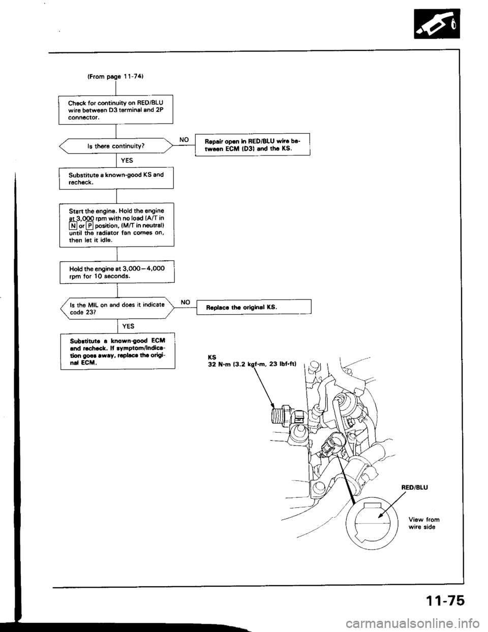
Chock tor continuitv on REO/8LUwirs botween D3 tormin6l 8nd 2Pconn6ctor.
Rop.ir op.n in RED/BLU wir. b.-
twcen ECM (D3l and th. KS.
Stsrt the engine. Hold th€ engine
st 3,000 rDm with no load (A/T in
@ or@ position, (lvt/t in neutratl
until the r6diator l6n comoa on,then l6t it idl€.
Hold the engin€ at 3,000-4,OOorDm lor 10 seconds.
Subrtitutr r known{ood ECM
.nd 6ch.ck. lt tymptoh/indic!-liarn goar away. raplaca lha otigi-nd ECM.KS32 N.m (3.2
wire side
11-75