engine ACURA INTEGRA 1994 Service Repair Manual
[x] Cancel search | Manufacturer: ACURA, Model Year: 1994, Model line: INTEGRA, Model: ACURA INTEGRA 1994Pages: 1413, PDF Size: 37.94 MB
Page 307 of 1413
Intake Air System
Throttle cable [81881 enginel
1 1-1 18
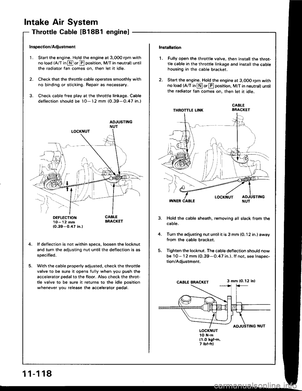
Inspection/Adiustment
'I . Start the engine. Hold the engine at 3,000 rpm with
no load (A/T in $ or@ oosition, M/T in neutral) until
the radiator fan comes on, then let it idle.
2. Check that the throttle cable operates smoothly with
no binding or sticking. Repair as necessary.
3. Check cable free play at the throttle linkage. Cable
deflection should be 1O-12 mm (O.39-O.47 in.)
DEFLECTION1O- 12 mm1O.39-0.47 in.l
4.lf deflection is not within specs, loosen the locknut
and turn the adjusting nut until the deflection is as
specifled.
With the cable properly adjusted. check the throttle
valve to be sure it opens fully when you push the
accelerator pedal to the floor. Also check the throt-
tle valve to be sure it returns to the idle oosition
whenever you release the accelerator pedal.
Installation
1. Fully open the throttle valve. then install the throt-tle cable in the throttle linkage and install the cablehousing in the cable bracket.
2. Start the engine. Hold the engine at 3,OOO rpm withno load (A/T in S or @ position, M/T in neutrall untilthe radiator tan comes on, then let it idle.
THBOTTLE LII{KCABLEARACKET
i;
-l-r
,)
j
5.
LOCKNUTITINER CABLE
Hold the cable sheath, removing all slack from the
cable.
Turn the adjusting nut until it is 3 mm (O. 12 in.) away
trom the cable bracket.
Tighten the locknut. The cable deflection should now
be 10- 1 2 mm (O.39 -O.47 in.). lf not, see Inspec-
tion/Adjustment.
3 mm {0.12 in)
LOCKNUT1O N.m{1.O kgl.m,7 tbt.ft)
Page 308 of 1413
Throttle cable [B18C1 enginel
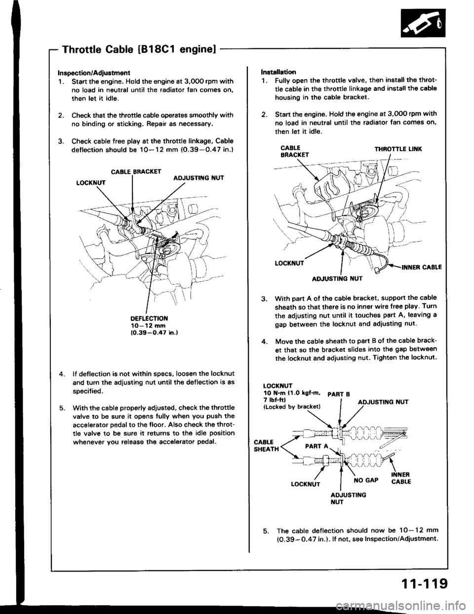
Inspection/Adiustment
1 . Start the engine. Hold the engine at 3,O0O lpm with
no load in neutral until the radiator fan comes on,
then let it idle.
2. Check that the throttl€ cable operates smoothly with
no binding or sticking. Repair as necessary.
3. Check csble free play at the throttle linkage, Cable
deflection should be 10-12 mm (O.39-O.47 in.)
DEFLECTIOI{10-12 mm(O.39-O.47 in.l
lf deflection is not within sDecs, loosen the locknut
and turn the adjusting nut until the deflection is as
specitied.
With the cable properly adjusted, check the throttle
valve to be sure it opens fully when you push the
accelerator Dedal to the tloor. Also check the throt-
tle valve to be sure it retums to the idle position
whenever vou release the accel€rator pedal.
CABLE BBACKET
ADJUSTING I{UT
lnstallation
1. Fullv open the throttle valve, then install the throt-
tle cable in the throttle linkage and install th€ cable
housing in the cable bracket.
2. Stan the engine. Hold the engine at 3,OOO rpm with
no load in neutral until the radiator fan comes on,
then let it idle.
THROTTLE LI K
With part A of the cabl€ bracket, support the cable
sheath so that there is no inner wire free play. Turn
the adjusting nut until it touches part A, leaving a
gap between the locknut and adiusting nul.
Move the cable sheath to psrt B of the cable brack-
et that so the bracket slides into the gap between
the locknut and adiusting nut. Tighten the locknul.
LOCKT{UTlO t{.m (t.O kgl.m, pART B
5.
4.
7 lbt.ftl{Locked by bracket)ADJUSTING NUT
PABT A
LOCKNUTNO GAP
AIUUSTINGNUT
5, The cable deflection should now be 10-12 mm
{O.39-O.47 in.). lf not, see Inspection/Adiustmsnt
11-119
Page 309 of 1413
lntake Air System
Throttle Body
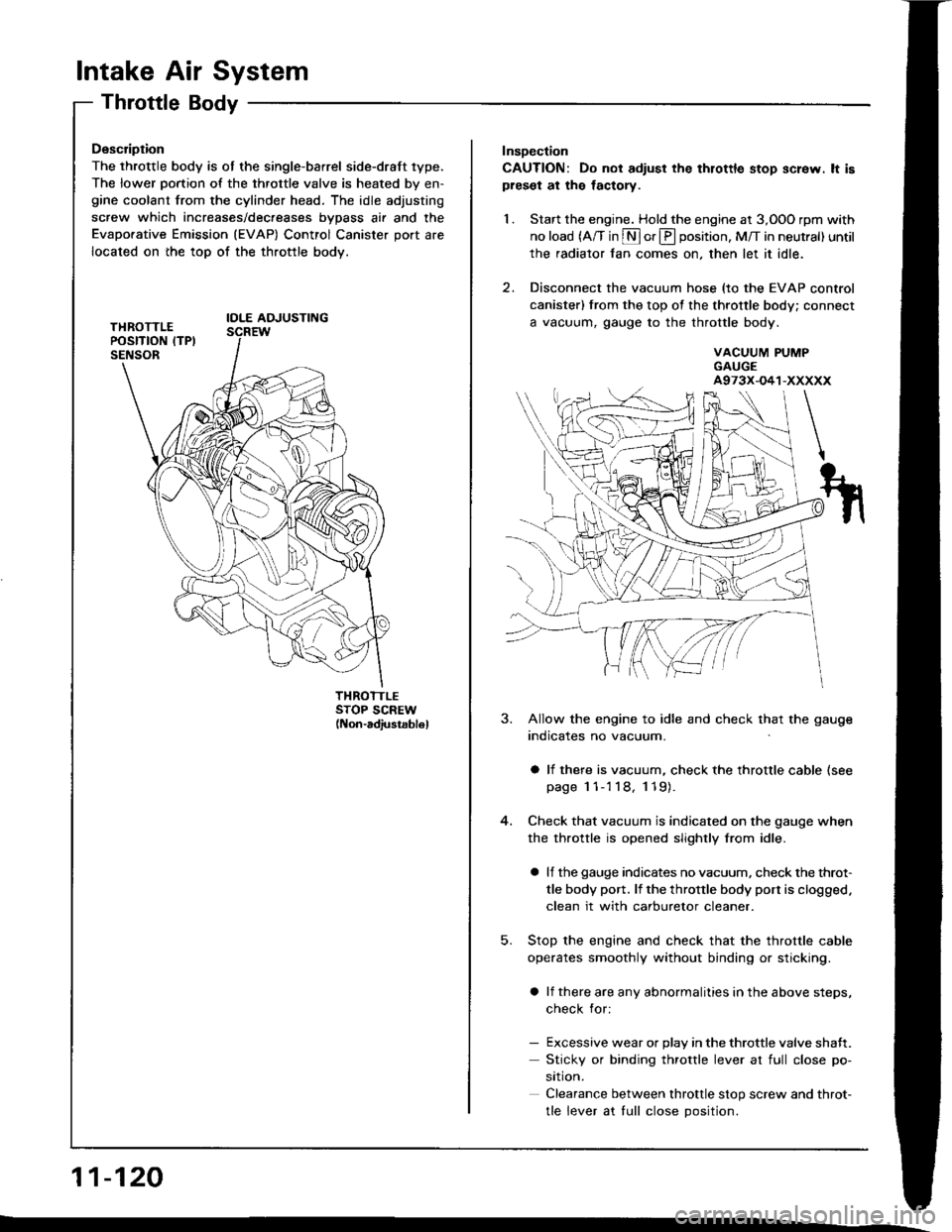
Description
The throttle body is ot the single-barrel side-draft 1ype.
The lower portion of the throttle valve is heated by en-gine coolant from the cylinder head. The idle adjusting
screw which increases/dec.eases bvDass air and the
Evaporative Emission (EVAP) Control Canister port are
located on the top of the throttle body.
IOLE AOJUSTING
THROTTLESTOP SCREW(Non-adiustsb16l
11-120
Insoection
CAUTION: Do not adiust the thlottle stop screw. lt ispreset at the lactory.
1. Start the engine. Hold the engine at 3,OOO rpm with
no load (A/T in S or E position, M/T in neutral) until
the radiator fan comes on, then let it idle.
2. Disconnect the vacuum hose (to the EVAP control
canister) from the top of the throttle body; connect
a vacuum, gauge to the throttle body.
VACUUM PUMPGAUGEA973X-O41-XXXXX
5.
3. Allow the engine to idle and check that the gauge
indicates no vacuum.
a li there is vacuum, check the throttle cable (see
page 1 1-'l 18, 119).
Check that vacuum is indicated on the gauge when
the throttle is opened slightly from idle.
a lf the gauge indicates no vacuum, check the throt-
tle body port. lf the throttle body port is clogged.
clean it with carburetor cleaner.
Stop the engine and check that the throttle cable
operates smoothly without binding or sticking.
a lf there are any abnormalities in the above steps,
check for:
- Excessive wear or Dlav in the throttle valve shaft.
Sticky or binding throttle lever at full close po-
srtron.
Clearance between throttle stop screw and throt-
tle lever at tull close Dosition.
Page 310 of 1413
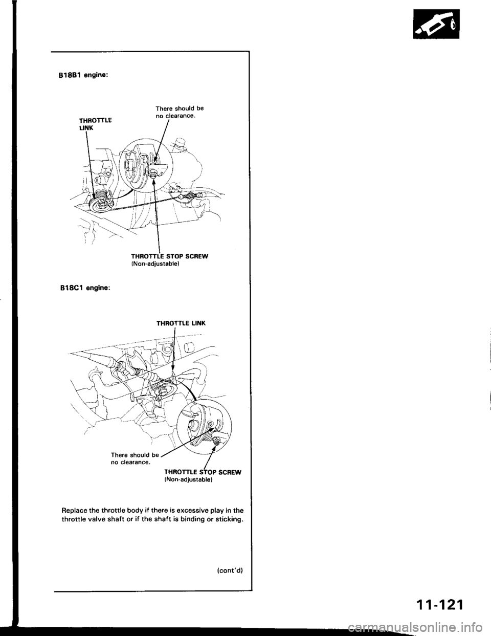
818B1 engino:
There should beno clearance.
THROTTLE STOP SCREW(Non-adiustablel
818Cl engine:
Replace the throttle body if there is excessive play in the
throttle valve shalt or if the shaft is binding or sticking.
THROTTLE LINK
(Non-adjusrablel
11-121
Page 312 of 1413
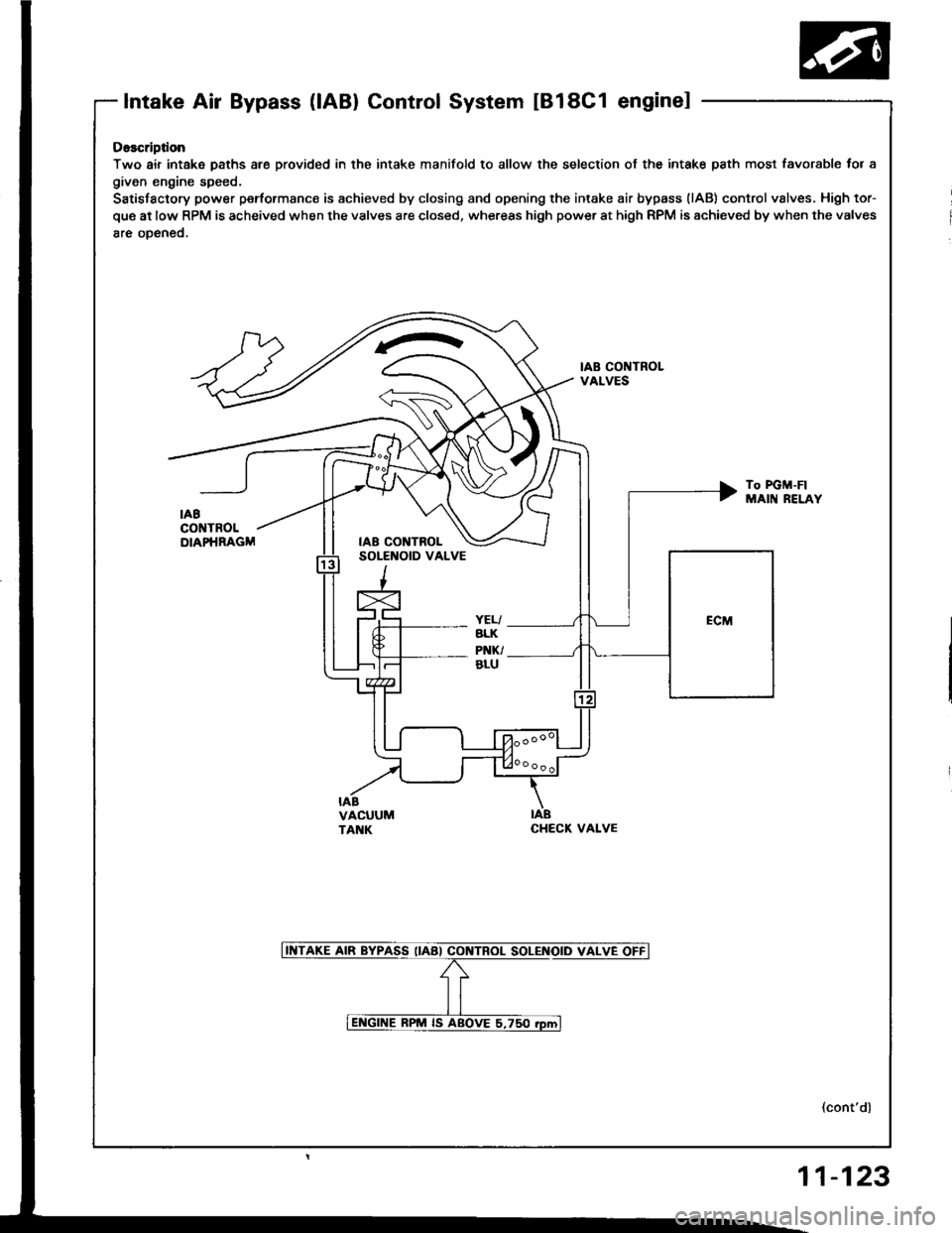
Intake Air Bypass (lABl Control System tBl8C1 enginel
Osscription
Two air intake paths are provided in the intake manifold to allow the selection of the intak€ path most favc
given engine speed.
Satisfactory power peformanc€ is achieved by closing and opening the intake air bypass (lAB) control valve!
que at low RPM is acheived when the valves are closed, whereas high power at high RPM is achieved by when
8re oDeneo.
IAB CONTROLVALVES
To PGM-FIMAIN RELi
IABCHECK VALVE
t favorabl€ for a
vslves. High tor-
when the valves
RELAY
(cont'dl
11-123
Page 313 of 1413
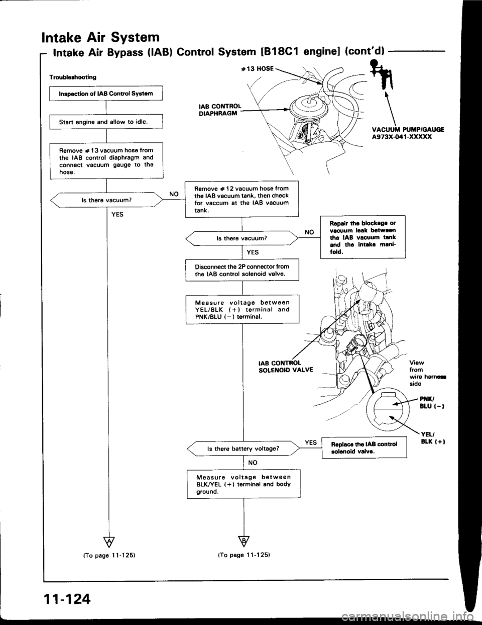
Intake
Intake
Air
Air
System
Bypass (lAB) ControlSystem tBl8C1 enginel (cont'dl
Troublcahooting
VACUUII PUMP/GAUG€A973X-041-XXXXX
fromwiro haanasid€
PI{K/BLU I-I
YEI/aLK l+l
tA8 COI{TROLDIAPHRAGM
Insp€ction of IAB Conltol Sytt.m
Start engino and allow to idle.
R€move # 13 vacuum hose tromthe IAB control diaph.agm andconnect vacuum gauge to thehose.
R€move # 12 vacuum hose fromth€ IAB vacuum tank, then checktor vaccum at the IAB vacuumtank.
Rcplir lh. block.g. otvacuufi laak boiwaaotha IAB vacuum tanklnd th. intlk m!ni-fold.
Disconnect the 2P conn€ctor lromthe IAB control solenoid valve.
Measure voltage betweenYEL/BLK (+l torminal andPNK/8LU l-) terminsl.
ls thoro battery voltage?
Measure voltage b€twee nBLK^|/EL (+) torminal and bodyground.
IAB CONTBOLSOLENOID VALVE
Page 314 of 1413
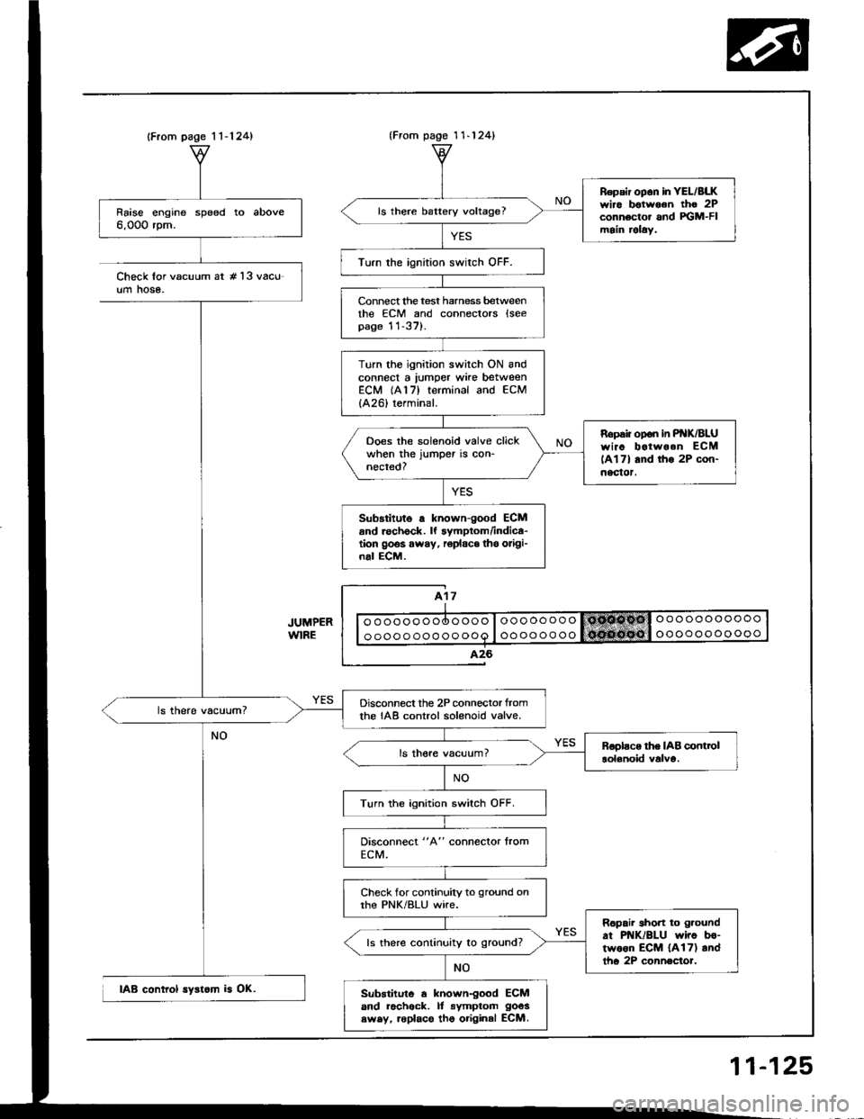
(From page 1 1-124)
Raise engine speed to above6,000 rpm.
Disconnect the 2P connector tromthe IAB control solenoid valve.
Turn the ignition switch OFF.
Check for continuity to ground onthe PNK/BLU wire.
Ropair short to g.ound
at PNK/BLU wiro bo-two6n ECM {A17) andtho 2P connector.
ls there continuity to ground?
Substituto a known-good ECMand racheck. It symptom goos
swsy, roplace tho original ECM.
{From pago 1 1-124}
Repsir op6n in YEL/BLKwiro botwoon tho 2Pconnector and FGM-FImain relaY.
ls there battery voltage?
Turn the ignition swirch OFF.
Connect lhe test harness betweenthe ECM and connectors lseepage 11-37).
Turn the ignition switch ON andconnect a lumper wke betweenECM (A17) terminal and ECM
{A26) terminal.
Ropaiiopon inP K/BLUwiao botwoen ECM
lAl7l and tho 2P con-nectot.
Ooes the solenoid valve clickwhen the jumper is con-nected?
Sub3titute a known-good ECMand rechock. lf symptom/indica-tion goos away, r6place tho origi-nal ECM.
Check lor vacuum at #'l3 vacu-um hose.
IAB control syst6m is OK.
11-125
Page 315 of 1413
a
Intake Air System
Intake Air Bypass (lABl Control Valve IB18C1 enginel
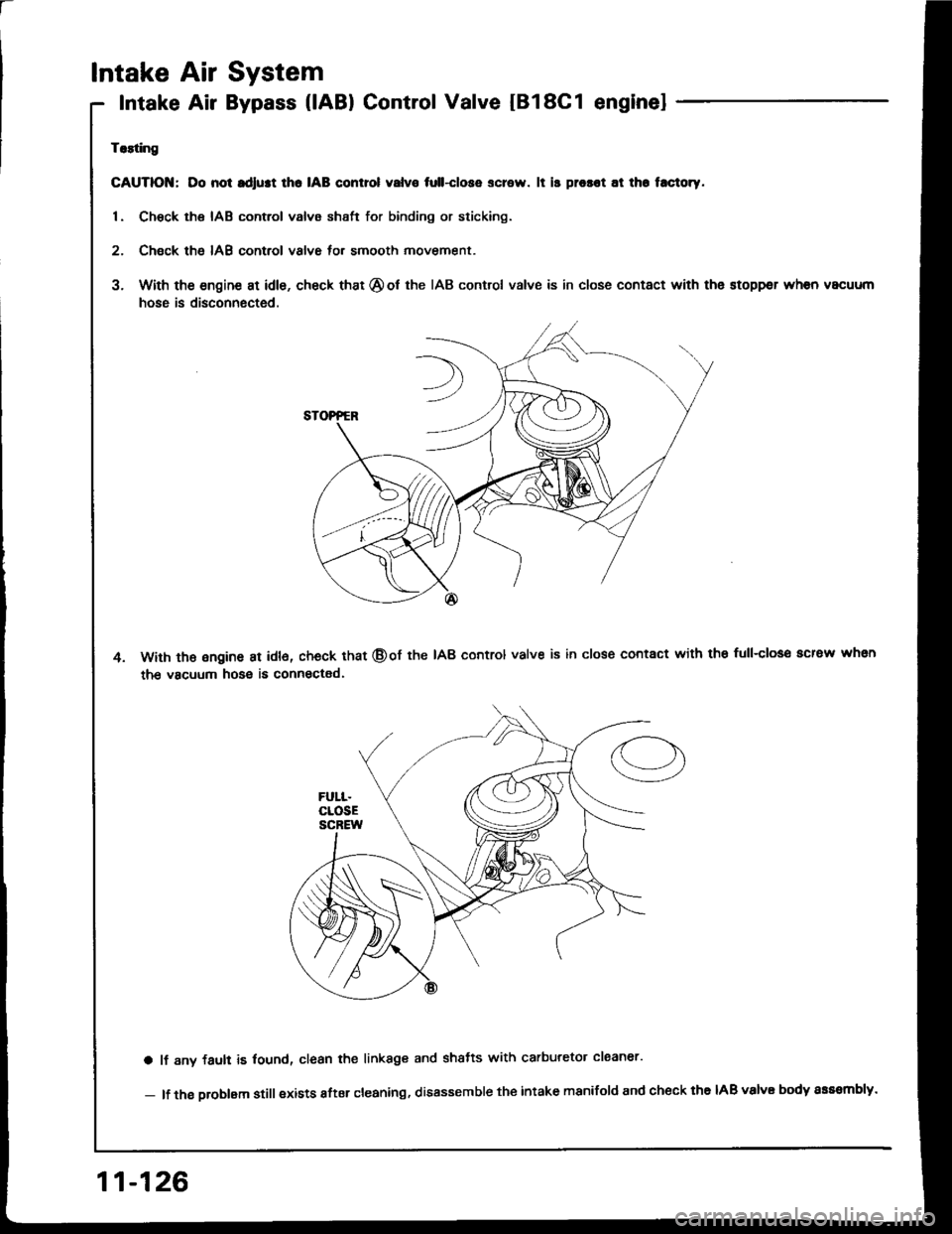
Trlting
GAUTIOI{; Do not rdlust lho IAB control valvo tull-close screw. lt is prosot at th. t.ctoty.
1. Chsck the IAB control valve shsft for binding or sticking.
2. Check th6 IAB control valve for smooth movement.
3. With the engine at idle, check that @ot the IAB control valve is in close contact with the stoppsr when vacuum
hose is disconnected.
With th€ ongine at idl6, check that @of the IAB control valve is in close contact with the full-closo acrew whsn
the vacuum hose is connectad.
a lf 8ny fault is lound, clean the linkage and shatts with carburetor claaner'
- lf the oroblam still exists after cleaning, disassemble the intake manifold and check the IAB valvE body sss8mbly.
11-126
Page 317 of 1413
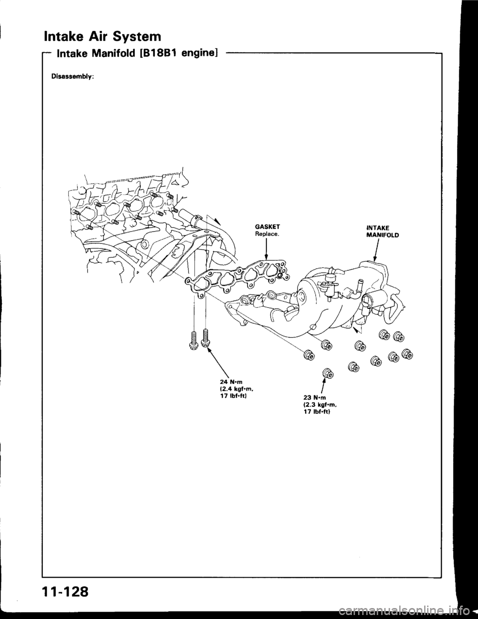
Intake Air System
Intake Manifold IB18B1 enginel
Disassembly:
{ uuu
24 N.m12.4 kgf.m,t7 tbt.ftl23 N'm(2.3 kgt.m,17 tbf.ftl
11-128
Page 319 of 1413
Emission Control System
SystemDescription
The emission control system includes a Three Way Cata-
lytic Convener (TWC), Positive Crankcase Ventilation(PCV) system and Evaporstive Emission {EVAP) Contfol
syst€m. The emission control system is designed to meet
federsl and stats emission standards.
Tailpipe Emission
Inspection
f!fifil oo nor amoro ou]rng rnr! Foacqurr. ^!op
any open flame away from yout wotk atca.
Start the engine. Hold the engine at 3,OOO rpm with
no load (A/T in @ or@ position, M/T in neutral) until
the radiator fan comes on, then let it idle,
Connect a tachometer.
Check and adiust the idle speed, if necessary (sss
page 1 1-95).
Warm up and calibrate the CO meter according to
the meter manutacturer's inst.uctions.
Check idle CO with the headlights, hester blower,
rear window defogger, cooling fan, and air condition-
er otf.
NOTE: (Canada) Pull the parking br8ke lever up.
Stan the engine, then check that the headlights are
off.
CO meter should indicate 0.1 maximum.
11-130