engine ACURA INTEGRA 1994 Service Repair Manual
[x] Cancel search | Manufacturer: ACURA, Model Year: 1994, Model line: INTEGRA, Model: ACURA INTEGRA 1994Pages: 1413, PDF Size: 37.94 MB
Page 289 of 1413
The fusl supply system consists ot a fuel tank, in-tank
high presssure fu6l pump, PGM-FI main relay, fuel filter,
tuel pressure regulatot, fuel inioctors, fusl pulsation
damper and fuol delivery and return linss. This system
delivers pressure-regulatored fu6l to the fu6l injectors and
cuts the fuel delivory wh6n the engine is not running.
Fuel Supply System
System DescriptionFuel Pressure
a Do not smok6 while working on the fuol syst6m,
Keep open flames or spalks away tlom your work
aroa.
a 8e sure to raliavo fuol p.essur6 while th6 6n9in6 is off.
NOTE: Eefore disconnecting fuel pipes or hoses, release
pressure from the system by loosening the 6 mm se.-
vice bolt on top of the fuel filter.
1 . Disconnect the battery negative cable from the bat-
tery negative terminal.
NOTE: The LS and GS-R model radio may have a
coded theft protection circuit. Be sure to get the cus-
tomer's code number betore disconnecting the
batterv,
After service, reconnect Dowe. to the radio and turn
it on. When the word "CODE" is displayed. enter
the customer's s-digit code to restore radio
ooeration.
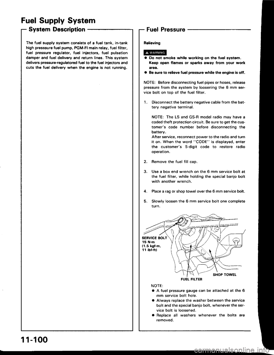
2. Remove the fuel fill cap.
3. Use a box end wrench on the 6 mm service bolt at
the fuel tilter, while holding the special banjo bolt
with another wrench.
4. Place a rag or shop towel over the 6 mm service bolt.
5. Slowly loosen the 6 mm service bolt one complete
turn.
NOTE:
a A fuel pressu.e gauge can be attached at the 6
mm seryice bolt hole.
a Alwavs replace the washer between the service
bolt and the special banio bolt. whenever the ser-
vice bolt is loosened.
a Replace all washers whenever the bolts are
removeo.
SERVICE BOLT15 N.m(1.5 kgf.m,11 rbr.ftl
FUEL FILTER
1 1-100
Page 290 of 1413
Insp6ction
1. Relieve fuel pressure (see page 11-1OO)
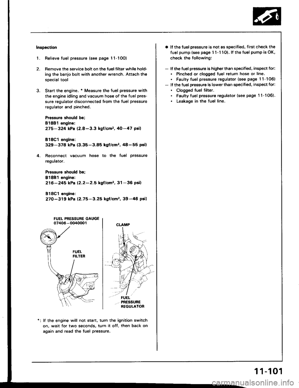
2. Remove the service bolt on the tueltilter while hold-
ing the banjo bolt with another wrench. Attach the
special tool
3. Siart the engine. * Measure the {uel pressur€ with
the engine idling and vacuum hose of the fuel pres-
sure regulator disconnected from the tuel pressure
regulator and pinched.
Pressure should b€;
818B1 engins:
275-324 kPa (2.8-3.3 kgl/cm2, 40-47 psil
818C1 ongine:
329-37a kPa (3.35-3.85 kgf/cmz, 48-55 pei)
4. Reconnect vacuum hose to the tuel plessure
regulator.
Prossuro should b€;
Bl8Bl ongino:
216-245 kPa (2.2-2.5 kgf/cm'�, 31 -36 psil
B18Cl on9in6:
27O-319 kPa 12.75-3.25 kgt/cm'�, 39-46 psi)
FUEL PRESSURE GAUGE07406 - OO4000 1
lf the engine will not stan, turn the ignition switch
on. wait for two seconds, turn it off, then back on
again and read the fuel pressure.
CLAMP
a lf the fuel pressure is not as specified, first check the
fuel pump (see page 1 l - 1 1O). lf the fuel pump is oK,
check the following:
- lf the fuel pressuro is higherthan specified, inspect for:
. Pinched or clogged tuel return hose or line.
. Faulty fuel pressure regulator (see page 11-106)
- It the fuel p.essu.e is lower than specitied, inspect fo.:
. Clogged fuel tilter.. Faulty fuel pressure regulator (see page '11-106).
. Leakage in the fuel line.
1 1-101
Page 291 of 1413
Fuel Supply System
Fuel Injectors
- --l- - \-l-l
116l- -ltc l-/---r- / ---i- \
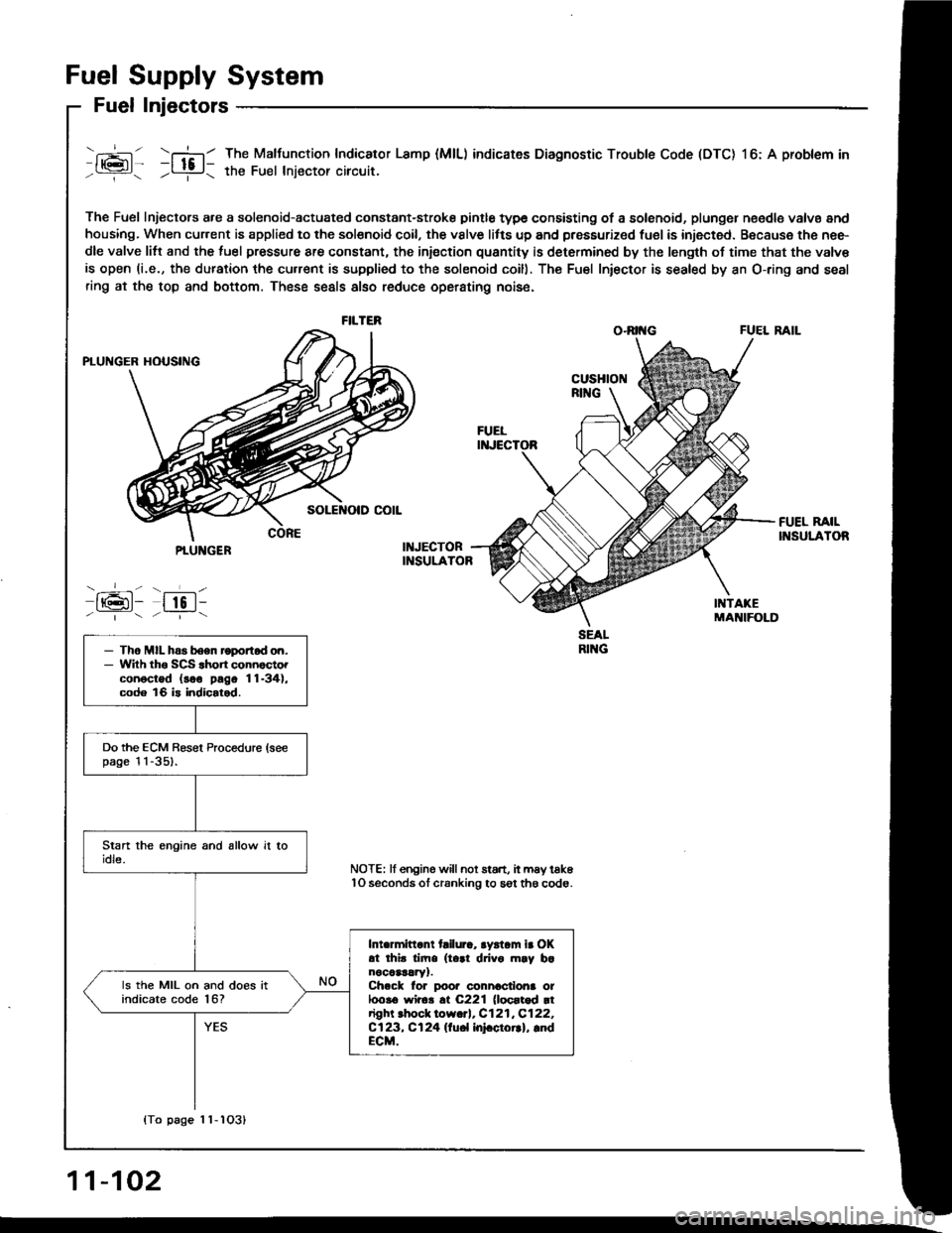
The Fuel Injectors a.e a solenoid-actuated constant-stroke pintle type consisting of a solenoid, plungel n€edle valvs and
housing. When cur.ent is applied to the solsnoid coil, the vslve litts up and pressurized fuel is injected. Because the nee-
dle valve litt and the luel pressure are constant, the iniection quantity is determined by the length of time that the valv€
is open (i.e., the duration the cu.rent is supplied to the solenoid coill. The Fu€l Iniector is sealed by an O-ring and seal
ring at the top and bottom. These seals also reduce operating nois6.
O.RII{G FUEL RAIL
The Malfunction Indicator Lamp (MlL) indicates Diagnostic Trouble Code (DTC) l6: A problem in
the Fuel lniector circuit.
FILTER
PTUNGER
-_-- - ___L-
IrGl- lto l--|.---:_-
- Tho MIL has boen roportod on.- Wilh tho SCS .hon connocto.conoctod (soo pago 11-34),code 16 is indicalod.
Do the ECM Besel Procedure (seepage l l -351.
Intermittant tailura, aystam ir OKat thir tim. (t..1 drivo m.y b.nocaar!ry1.Ch.ck lor poor connactiona ot100!6 wir6!.t C221 (loortod rtright .hock low.rl, C121,C122,Cl23, Cl24 llu6l InFctorrl, lndECM.
ls the MIL on and does itindicate code l6?
NOTE: lf engine willnot start, it may tak6lO seconds ol cranking to sgt th6 code.
{To page 1 1-1O31
11-102
Page 294 of 1413
Rapl!c!ment
@ oo not smoko during tho work. Keep open
fllma3 lway from your wolk aloa.
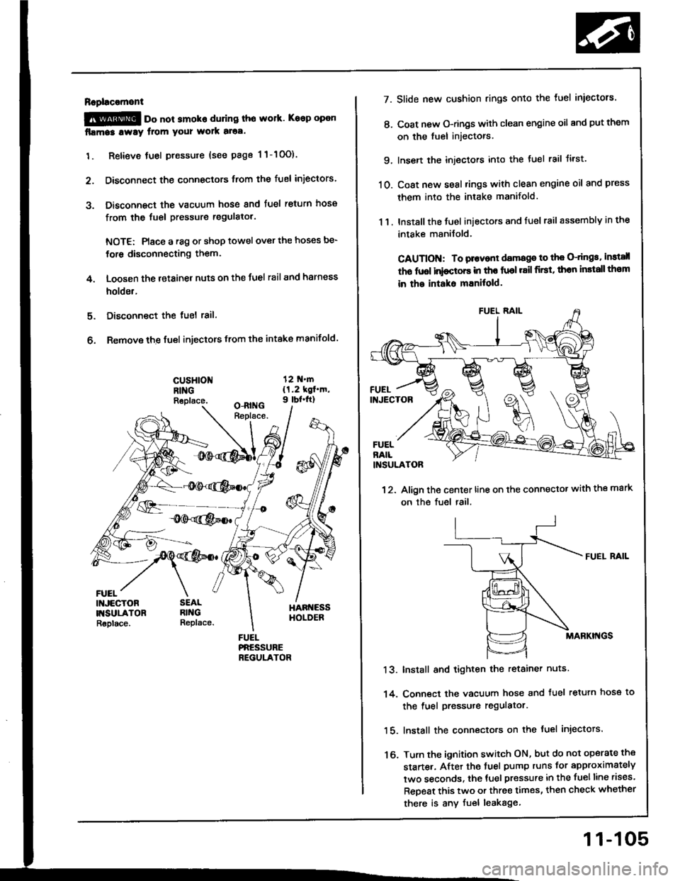
1. Retieve tuel pressure {see page 1 1-10O).
2. Disconnect the connectors trom the fuel iniectors.
3. Disconnect the vacuum hose and fuel return hosa
from the fuel pressure regulatol.
NOTE: Place a r8g or shop towel over the hoses be-
for6 disconnecting them.
4. Loosen the retainer nuts on the Juel rail and harness
holder.
Disconnect the tuel 18il.
Remove the fuel injectors from the intake manifold.
5.
6.
cusHloNRINGReplace.
FUEL
7.
t'.
9.
10.
13.
14.
16.
11.
Slide new cushion rings onto the luel iniectors.
Coat new O-rings with clean engine oil and put them
on the fuel injectors.
Insen the injectors into the tuel rail tirst.
Coat new seal rings with clean engine oil and press
them into the intake manifold.
Install the Juel iniectors and fuel rail assembly in the
intake manilold.
CAUTION: To plovont damage to th€ O-dngs, instsll
tho fuol inioctors in tho fuol r8il first, thon install th€m
in the intaks mEnitold.
12. Align the center line on the connector with the mark
on the fuel rail.
FUEI. RAIL
MABKI'{GS
Install and tighten the retainer nuts
Conn€ct the vacuum hose and tuel retuln hose to
the fuel pressure regulator.
lnstall the connecto.s on the fuel injectors.
Turn the ignition switch ON, but do not operate the
starte.. After the tuel pump runs for approximately
two seconds, the tuel pressure in the fuelline rises.
ReDeat this two or three times, then check whether
there is any fuel leakage
11-105
Page 295 of 1413
Fuel Supply System
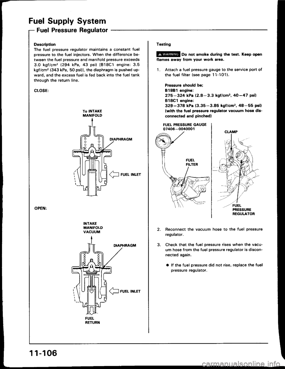
Fuel Pressure Regulator
FUELRETURI{
Description
The fuel pressure .egulator maintains a constant Juel
pressure to the tuel injectors. When the difference be-
tween the fuel pressure and manitold pressur€ exceeds
3.O kgf/cm'� 1294 kPa, 43 psi) tB18C1 engine: 3.5
kgt/cm, (343 kPa, 50 psi)], the diaphragm is pushed up-
ward, and the excess fuel is fed back into the fuel tank
through the retufn line,
CLOSE:
DIAPHRAGM
__l FUEL INLET
INTAKEMA'{IFOLDVACUUM
DIAPHNAGM
/1-
\J FUEL INLET
11-106
Te6ting
@ oo not smoko during the t€st. Ko6p opon
flames away from your work area,
1. Attach a fuel pressure gauge to the se.vice port of
the luel filter {see page 11-101).
Prossuro should be;
Bl88l ongin€:
275-324 kPa (2.8-3.3 kgf/cm', 40-47 psil
B18Cl €ngino:
329-378 kPa (3.35-3.85 kgf/cm'�.48-55 pEi)
(with tho tuol pressure rsgulator vacuum hoso dls-
connoctod and pinched)
FUEL PRESSURE GAUGE07406 - oO/IOOO 1
Reconnect the vacuum hose to the fuel pressure
regulator.
Check that the tuel pressure rises when the vacu-
um hose from the fuel pressure regulator is discon-
nected again.
a lf the fuel pressure did not rise, replace the fuel
pressure regulatot.
Page 296 of 1413
Raplacoment
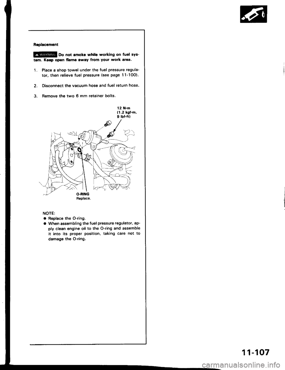
@ oo not amoko whil6 working on fuel sys-
tam. Koop open flamo away tlom your work atea'
1. Place a shop towel under the fuel pressure regula-
tor, then reliev€ tuel pressure (see page 1l-10O).
2. Disconnect the vacuum hose and fuel return hose.
3. Remove the two 6 mm retainer bolts.
12 N.m{1.2 kgl.m,9 rbf.ft)
NOTE:
a Replaco the O-ring.
a When assembling the fuel pressure regulator, ap-
ply clean engine oil to the O-ring and assemble
it into its proper position, taking care not to
damage the O-dng.
Rsplace.
11-107
Page 297 of 1413
Filter
Fuel Supply System
Fuel
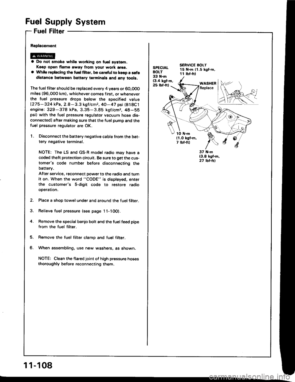
a Do not smoko while wo*ing on tusl system.
Keop open tlame away ftom your wotk area.a While replaclng th6 tusl liher, be caletul to koop a safodistanc6 betweon battery torminals and any tool3.
The Juel filter should b€ replaced every 4 years or 60,0O0miles (96,OOO km), whichever comes f irst. or wheneverthe fuel pressure drops below the specilied value
127 5 - 324 kPa, 2.8 - 3. 3 kgJ/cmr, 40-47 psi (Bl 8C 1engine: 329-378 kPa, 3.35-3.85 kgf/cmr, 48-55psi) with the fuel pressure regulator vacuum hose dis-
connectedl afte. making sure that the tuel pump and thefuel pressure regulator are OK.
1 , Disconnect the battery negative cable trom the bat-
tery negative terminal.
NOTE; The LS and GS-R model radio may have acoded theft protection circuit, Be sure to get the cus-
tomer's code number before disconnecting the
batterv.
After service, reconnect power to the tadio and turn
it on. When the word "CODE" is displaved, enter
the customer's 5-digit code to restore radio
operation.
2. Place a shop towel under and around the fueltilter.
3. Relieve fuel pressure (see page 11-100).
4. Remove the special banio bolt and the fuel feed pipe
from the fuel tilter.
Remove the fuel filter clamp and tuel Jilter.
When assembling, use new washers, as shown,
NOTE: Clean the llared joint ot high pressure hoses
thoroughly before reconnecting them,
1 1-108
SPECIALBOLT33 N.m(3.4 kgt.h,25 rbf.ft)
SERVICE BOLT15 N.m ll.5 kgt.m,1 I rbr.ftl
WASHERReplace
1O ttl.m(1.O kgf.m,7 tbt.ftl
Page 298 of 1413
[":::,::-'
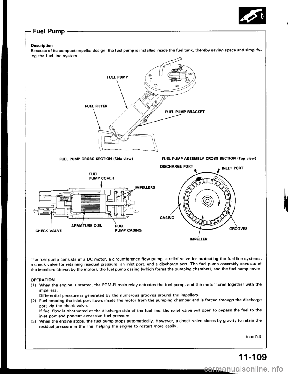
Eecause of its compact impeller design, the fuel pump is installed inside the fueltank, thereby saving space
ng the fuel line system.
FUEL PUMP
FUEL FILTER
FUEL PUMP BRACKET
FUEL PUMP CROSS SECTION lsido vi6rvl
IMPELLERS
CHECK VALVEPUMP CASING
The fuel oumo consists of a DC motor, a circumference flow pump, a relief valve for ptotecting the fuel lir
a check valve for retaining residual pressure, an inlet port, and a discharge port. The fuel pump assembly
the impellers (driven by the motor), the fuel pump casing {which forms the pumping chsmber), and the fuel p
OPERATION(1 ) When the engine is started. the PGi/t-Fl main relay actuates the fuel pump, and the motor turns togeth
impellers.
Differential pressure is generated by the numerous grooves around the impellers.
(2) Fuel entering the inlet porr flows inside the motor from the pumping chambe. and is forced through th
port via the check valve.
lf tuel flow is obstructed at the discharge side of the tuel line, the relief valve will open to bypass the
inlet port and prevent excessive fuel pressure.
(3) When the engine stops, the tuel pump stops automatically. However, a check valve closes by gravity t
residual pressure in the line, helping the engine to aestan more easily.
and simplify-
N lTop vi6w)
PORT
GROOVES
fuel line systems,
embly consists of
fuel pump cover.
together with the
rgh the discha.ge
ss the fuel to the
avitv to retain the
(cont'd)
PUMP COVER
FUEL PUMP ASSEMBLY CROSS SECTION
D|SCHARGE FORT ^ . tNLEr P
IMPELLER
11-109
Page 300 of 1413
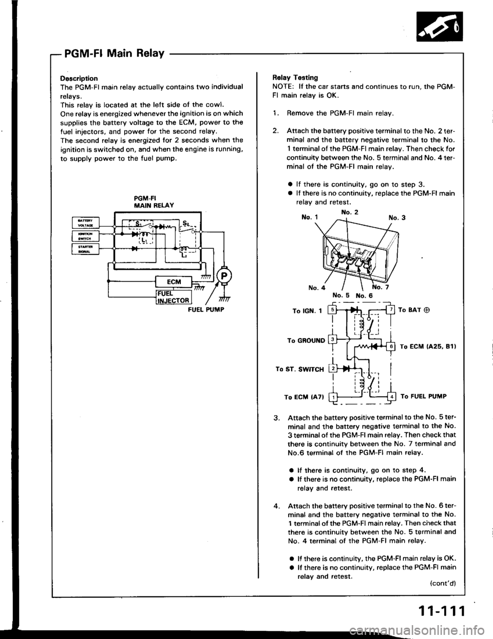
PGM-Fl Main Relay
Doscription
The PGM-Fl main relav actuallv contains two individual
rerays.
This relay is located at the lett side of the cowl.
One relay is energized whenever the ignition is on which
supplies the battery voltage to the ECM, power to the
fuel injectors, and power for the second relay.
The second relay is energized for 2 seconds when the
ignition is switched on, and when the engine is running,
to supply power to the fuel pump.
PGM-FIMAIN RELAY
FUEL PUMP
Relay Testing
NOTE: lf the car stans and continues to r
Fl main relay is OK.
1. Remove the PGM-Fl main relay.
2. Attach the battery positive terminalto
minal and the battery negative termir
1 terminal of the PGM-FI main relay. T
continuity between the No. 5 terminal
minal of the PGM-FI main relay.
a lf there is continuity, go on 10 ste
a lt there is no continuity, replace the
relay and retest.
To lGN. I
To GROUND
To ST. SWITCH
To ECM {47}
Attach the battery positive terminalto
minal and the battery negative termil
3 terminal of rhe PGM-Fl main .elav. Tl
there is continuity between the No. ;
No.6 terminal of the PGM-Fl main re
a lf there is continuity, go on to st€
a lf there is no continuity, replace th€
relay and retest.
Anach the battery positive terminalto
minal and the battery negative termil
1 terminalof the PGM-Fl main relay, Tl
there is continuity between the No. :
No. 4 te.minal of the PGM-Fl main r
a It there is continuitv, the PGM-FI mi
a lf there is no continuity, replace th(
relav and retest.
No.2
run, the PGM-
nalto the No. 2 ter-
terminal to the No.
lay. Then check for
minal and No. 4 ter-
to step 3.
ce the PGM-Fl main
8Ar C)
ECM {425, 81)
J To FUEL PUMP
inalto the No. 5 ter-
terminsl to the No.
ay. Then check that
No. 7 terminal and
ain relay.
to step 4.
ce the PGM-Fl main
inal to the No. 6 ter-
terminal to the No.
ay, Then check that
No. 5 terminal and
nain relay.
-Flmain relay is OK.
ce the PGM-Fl main
(cont'd)
11-111
Page 305 of 1413

Intake Air System
System Description
The system supplies air for allengine needs. lt consists of the intake air pipe, Air Cleaner (ACL), intake air duct, Throttle
Body (TB), ldle Air Control {lAC) Valve, tast idle thermo valve, and intake manifold.
A resonator in the intake air pipe provides additional silencing as air is drawn into the system.
nacot{TRoLSOLENOIDVALVE
To
ffi -------------+ i'"ii'i''RELAY
VARIOUSSENSORS
IABCONTROLDIAPHRAGMVALVE
-BLK--L EI{GINE- cooLnnt
tFASTIDLETHERMOVALVE
U
INTAKEAIR PIPE
INTAKEAIRDUCT
11-116