sensor ACURA INTEGRA 1994 Service Workshop Manual
[x] Cancel search | Manufacturer: ACURA, Model Year: 1994, Model line: INTEGRA, Model: ACURA INTEGRA 1994Pages: 1413, PDF Size: 37.94 MB
Page 437 of 1413

Component Location
)/
,/s\
{7v
A0t
AUTOMATIC TRANSAXLE IA/TIGEAR POSITION SWITCH
VEHICLE SPEEDSENSOR {VSSI
COUNTERSHAFTSPEED SEf{SORMAINSHAFT SPEEDSENSORTHROTTLE POSITION (TP}SENSOR
at
,
)''ENGINE COOLANT TEMPERATURE (ECTISENSOR
14-45
Page 439 of 1413

A/CCOMPRESSORCLUTCHREI.AY
. VEHICI.E SPEEDSENSOR. SPEEOOMETER
SERVICE CHECKCONNECTOR
D9 013 011 Dl6 D3 D6 D7
TMNSMISSION CONTROL MODULE {TCM}
Dls 019
/8tK'HBOTfLE ENE'NEPostto^l coolAlvrSENSOR TEMPERA.TURESENSOR
Dl2
D5 A25 A26
A5 A3I
I.OCK'UP CONTROLSOLENOID VATVESHIFTCONTROLSOLENOIO VALVE
COUNTERSHAFTSPEEO SENSORMAINSHAFISPEED SENSOR
A3A5A9A1:421
A6A8A1(,/1,/1,/A1t
TCM T6rmin6l Locations
14-47
Page 442 of 1413
![ACURA INTEGRA 1994 Service Workshop Manual Symptom-to-Component Chart
Electrical System
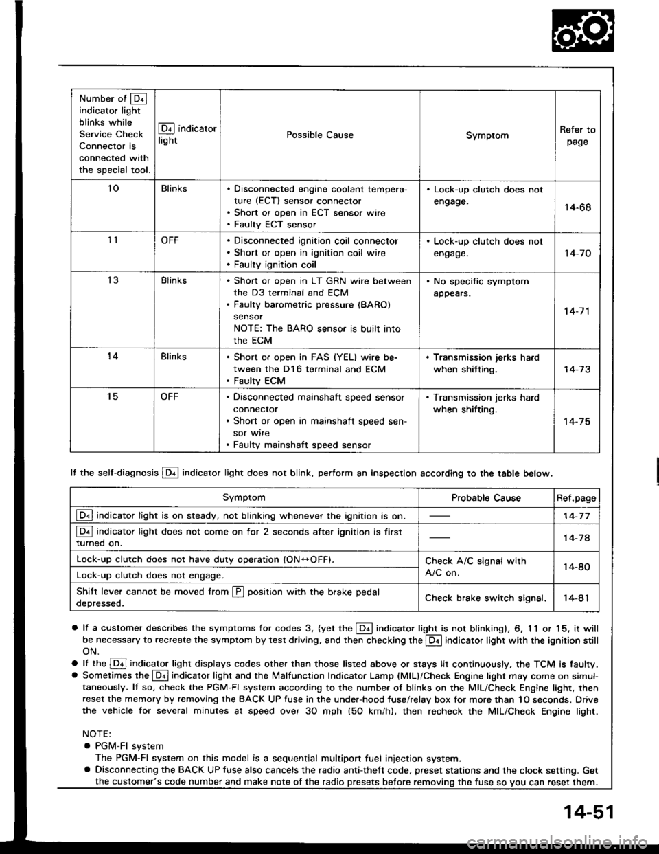
Number of @indicator light
blinks while
Service Check
Connector is
connected with
the special tool.
@] indicaror
lightPossible CauseSymptomRefer to
page
Bl ACURA INTEGRA 1994 Service Workshop Manual Symptom-to-Component Chart
Electrical System
Number of @indicator light
blinks while
Service Check
Connector is
connected with
the special tool.
@] indicaror
lightPossible CauseSymptomRefer to
page
Bl](/img/32/56982/w960_56982-441.png)
Symptom-to-Component Chart
Electrical System
Number of @indicator light
blinks while
Service Check
Connector is
connected with
the special tool.
@] indicaror
lightPossible CauseSymptomRefer to
page
BlinksDisconnected lock-up control solenoidvalve A connector
Short or open in lock-up control sole-noid valve A wire
Faulty lock-up control solenoid valve A
Lock-up clutch does not
engage.
Lock-up clutch does not
disengage.
Unstable idle speed.
14-52
BlinksDisconnected lock-up control solenoidvalve B connector
Short or open in lock-up control sole-noid valve B wire
Faulty lock-up cont.ol solenoid valve B
. Lock-up clutch does not
enga9e.
14-54
Blinks or
OFF
Disconnected throttle position (Tp)
sensor connector
Short or open in TP sensor wireFaully TP sensor
. Lock-up clutch does not
engage.14-56
4BlinksDisconnected vehicle speed sensor(VSS) connector
Short or open in VSS wire
Faulty VSS
. Lock-up clutch does not
engage.'t 4-57
Blinks. Short in A/T gear position switch wire. Faulty A/T gear position switch
. Fails to shift other than
2nde4th gears.. Lock-up clutch does not
engage.
14-58
OFFDisconnected A/T gear position switch
connector
Open in A/T gear position switch wireFaulty A/T gear position switch
Fails to shift other than
2nd-4th gears.
Lock-up clutch does not
en98ge.
Lock-up clutch engages
and disengages alter-
nately.
14-60
7BlinksDisconnected shift control solenoidvalve A connector
Short or open in shitt control solenoidvalve A wire
Faulty shift control solenoid valve A
. Fails to shift (between
1st-4th, 2nd-4th or
2nd-3rd gears only).. Fails to shift (stuck in
4th gear).
14-62
8BlinksDisconnected shitt control solenoid
valve B connector
Shon or open in shift control solenoidvalve B wi.e
Faulty shift control solenoid valve B
. Fails to shiJt (stuck in
lst or 4th gears).'t 4-64
aBlinksDisconnected countershatt speed sen-sor connector
Short or open in the countershaft
speed sensor wire
Faulty countershaft speed sensor
. Lock-up clutch does not
engage_
14-50
Page 443 of 1413

Number of @indicator light
blinks while
Service Check
Connector is
connected with
the special tool.
@ indicator
lightPossible CauseSymptomRefer to
page
'loBlinksDisconnected engine coolant tempera-
rure (ECT) sensor connector
Short or open in ECT sensor wire
Faulty ECT sensor
Lock-up clutch does not
engage.14-68
1lOFFDisconnected ignition coil connector
Short or open in ignition coil wire
Faulty ignition coil
. Lock-up clutch does not
engage.'t 4-7 0
13Blinks. Shon or open in LT GRN wire between
the D3 terminal and ECM. Faulty barometric pressure {BARO)
sensor
NOTE: The BARO sensor is built into
the ECM
. No specific symptom
appears.
14-7 1
14Blinks. Short of open in FAS {YEL} wire be-
tween the D16 terminal and ECM. Faulty ECM
. Transmission jerks hard
when shitting.
't5OFFDisconnected mainshaft speed sensor
connecror
Short or open in mainshaft speed sen-
sor wire
Faulty mainshaft speed sensor
. Transmission jerks hard
when shifting.
14-75
SymptomProbable CauseRet.page
LQ! indicator light is on steady, not blinking whenever the ignition is on.14-77
[Q3] indicator light does not come on for 2 seconds after ignition is first
turned on.14-78
Lock-up clutch does not have duty operation (ON-OFFI.Check A/C signal with
A/C on.14-80Lock-up clutch does not engage.
Shitt leve. cannot be moved lrom @ position with the brake pedal
depressed.Check brake switch signal,14-41
It the self-diagnosis LQ4 indicator light does not blink, perform an inspection according to the table below.
a lf a customer describes the symptoms for codes 3, (yet the LQ! indicator light is not blinkingl, 6, 1 1 or 15, it will
be necessa.y to recreate the symptom by test driving. and then checking the @ indicator light with the ignition still
oN.
e lt ttre @ indicator light displays codes olher than those listed above or stays lit continuously, the TCM is faulty.. Sometimes the Lqd indicator light and the Malfunction Indicator Lamp (MlL)/Check Engine light may come on simul-taneously. lf so, check the PGM-Fl system according to the numbe. of blinks on the MIL/Check Engine light. thenreset the memory by removing the BACK UP fuse in the unde.-hood fuse/relay box for more than 1O seconds. Drive
the vehicle for several minutes at speed over 30 mph (5O km/h), then recheck the MIL/Check Engine light.
NOTE:
. PGM-FI system
The PGM-Fl system on this model is a sequential multiport fuel injection system.a Disconnecting the BACK UP luse also cancels the radio anti-theft code. preset stations and the clock setting. Get
the fuse so vou can reset them.the customer's code number and make note ot the radio
14-51
Page 449 of 1413

S. d.gno.b lql indic.to. lightbllnkr tour tlm...
R.lor to Soctlon 23 for vohiclerpood lonsoi {vSSl to!t.
Shift t.nsmisiion to A position.
Ch6ck to. shoft or opon in OFilwlro b€twoen tho .)9 t6tminsl andrho VSS. lf wiro is OK, ch€ck thoVSS lsoo soction 231.
Doss lhe voltage O V and ap-p.ox. 10 V appe.r alternately?
Ch.d( tor loo.. TCM co.!n.cto.r.ll nacaaalay, lubrtituta ! known_geod TCM and t chock.
Possible Caus6
. Disconnectsd vehicle speedsensor {VSS} connector. Short or open in VSS wire. Faulty VSS
Disconn6ct the 26Pand 22P con-n.ctors trom th€ TCM.Connect ths Tgst Harnoas "A"
8nd "O" connectors to tho wireharnsss only, not to the TCM (see
page 1+49).
Turn the ignilion switch ON.
a Mak€ sure lifts,lacks, and safety stands aro placod plopor-
ly {see Eaclion 1}.
a S6t th6 parking brake eecurely and block tho tear wh6ol3'
a Jack up tho f.ont ot tho car and rupport whh sstoty standa.
(cont'd)
Rotat€ th€ tront wh6ol and chsckfo. volt6g€ botwean the D9 andA25 o. A26 terminals. Block theother whaol 30 it do€s not turn.
14-57
Page 458 of 1413

Electrical Troubleshooting
Troubleshooting Flowchart {cont'dl
ls the countershaft speedsensor installed properly
2P CONNECTOR
COUNTERSHAFTSPEED SENSOR
Possible Cause
. Loose or faulty connection be-rween the TCM and car harness.. Disconnected countershaft speedsensor connector. Short or open in the counter-shatt speed sensor wire. Faulty counlershaft speed sensor
Self-diagnosis Lq! indicator lighrblinks nino timos.
Disconnect the 2P conneclor lromthe countershaft speed sensorconnector,
Measure the resistance ot theco!ntershaft speed sensor.
ls the resistance 4OO 600 0?
To page 14-67
14-66
Page 459 of 1413

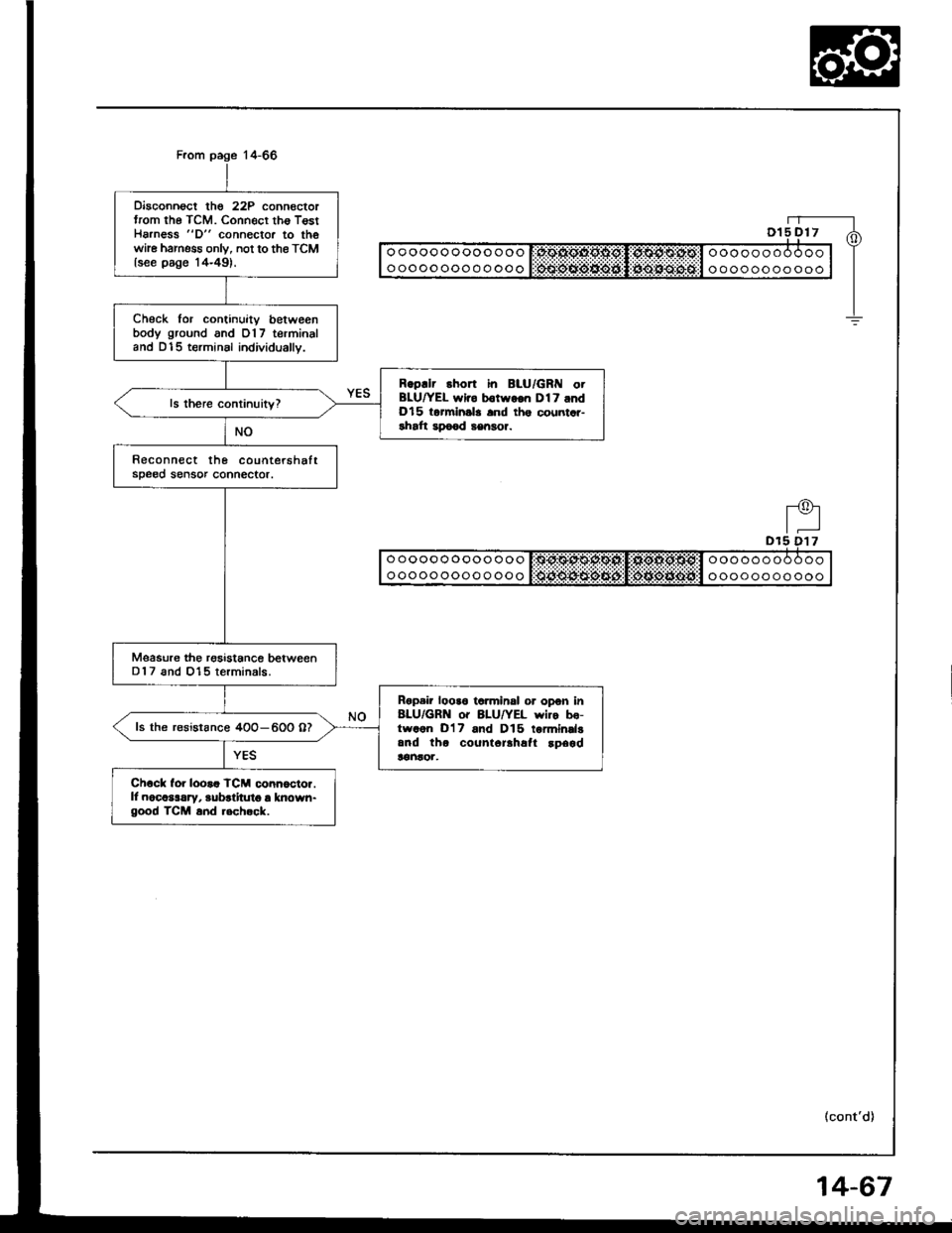
Disconnoct the 22P connectortrom the TCM. Connecr tho T€stHarness "D" connector to thewhe harness onlv, not to the TCMlsee page '14-49).
Check for continuitv betweenbody ground and 017 terminaland D15 terminsl individually.
Rgpllr short in BLU/GRI{ otBLU|/EL wlro b€twgon Dl7 andDl5 torminsla and ths countar-rhaft apo€d sengor.
Reconnect the countershaftsDe00 sensor connector.
Msasure the rgsistance betweenD 1 7 and 015 terminals.
Rgpair looa6 ta.minsl or opon in8LU/GRN o. 8LU/YEL wiro bo-trvaon D'17 and D15 tormindgand tho count6rlhafl !p6gd!€ntor,
ls the r€sistance 4OO-600 07
Ch6ck for looaa TCM conn6cto..ll nocaslrry, aubrlitut6 a known-good TCM a.d .6ch.ck.
(cont'd)
4-67
Page 460 of 1413

Electrical Troubleshooting
Troubleshooting Flowchart (cont'dl
Possibl€ Caus6
. Disconnoct€d engine coolantt€mp€rature (ECTI sensor con-noctor. Short or open in the ECT sensor
. Faulty ECT s€nsor
Self-diagnosis E indicator lightblinks ten times.
Turn the ignition switch ON.
Check whether the MalfunctionIndicator Lamp {MlL} blinks (seesection 1 1)-
ls the MIL blinking?Rop.ir tho PGM-FI Syrt.m (!go
!.ction 111.
Turn the ignition switch OFF.
Disconnectthe 26P and 22P con-nectors trom the TCM.Connect the Test Harness "A"
and "D" conneclors to the wireharness only, not to the TCM (seepage 14 49).
Measure the voltage between theD'18 and A25 or A26 lorminals.
Bopair op.n or .hofi In WHT/BLKwiro botwoon tho O18 tanni.|al.nd the ECM.ls the voltage 4.75-5.25 V?
Turn the ignition switch OFF.
oooooooooooo
ooooooooooooooooooooooo
oooo o oo o
Dlal + I
Page 463 of 1413

Disconnect lhe 26Pand 22P con-nectors trom the TCMConnect the Test Hahess "A"
and "D" connectors to the wireharness only, not to th€ TCM {seepare'14-49).
Possible Cause
. Short or open in LT GRN wire between the D3terminal and the ECM.. Fauky the barometric pressure {8ARO} sensor.NOTE: The BARO sensor is built into lhe ECM.
ooooooooooooo
oooooooooooo0oOOqgopg I,oiOOOOol ooo ooooooooooocqooo:Joo.oipggl o oooooo o 9ooTurn the ignition swirch ON.
Measure the voltage between theD18 and A25 or A26 terminals.
ls the voltage 4.75-5.25 V?
Turn the ignition swith OFF.
A25t- |
Soll-diagnosis Lq! indicator lightblinks thirtoon tim6.
ls rhe Malfunction lndicatorLamp (MlL) on and does itindicate code 13?
Do the TCM Rest Procedure (seepage 14-49).
Turn the ignition switch ON.
Substituto a known-good ECM and rechock.ll symptom/lndicationgoos away, .oplace theoriginal ECM.
ls the MIL on and does itindicare code 13?
Turn the ignition switch OFF.
Ropair opon or short in WHT/BLKwir6 botwoon th€ D18 to.minaland tho EcM.
fo page 14-72
14-71
Page 467 of 1413

Possible Cause
. Disconnected mainshaft speedsensor connecror. Short or open in mainshaltspeed sensor wrre.. Faulty mainshatt speed sensor.
NOTE:. A code 15 on the TCM doesn't alwsysmean there's an electrical problem in themainshaft or countershaft speed sensor cir-cuit; code '15 may also indicate a mechani-cal Droblem in the transmission.
3P CONNECTOR
II o o o o o o o oo o o o o I:OtlO$O$g:Sl!:OlXOl*Ofill o o o o o o o o o O o | |
I ooooooooooooo l Sciii:ddii:ijii:l:i$idi$;d6#:l o oooop oo ooo | 6
"-f
1-L(0)Y-!
(cont'd)
solf-diagnosis E indicator lightblink tiftoon timos.
Are the mainshaft and counter-shalt speed sensors installedproperly?
Disconnect the 3P connector lromthe mainshaft speed sensor.
Measure the resistance ot themainshaft speed sensor.
ls the resistance 4OO-600 O?
Disconnect the 22P connectorfrom the TCM.Connect the Test Harness "D"
conneclor to the wire harnessonly, not ot the TCM (see page14-49).
Check the continuity betweenD19 and D12 terminals and bodyground.
Rcoair short in ORN/BLU otWHT/BLU wiros botween Dlgand Dl2 to.minals and tho main-shatt speod ronsor.
Reconnect the 3P connector tothe mainshatt speed sensor,
To page 14-76
14-75