engine ACURA INTEGRA 1994 Service Repair Manual
[x] Cancel search | Manufacturer: ACURA, Model Year: 1994, Model line: INTEGRA, Model: ACURA INTEGRA 1994Pages: 1413, PDF Size: 37.94 MB
Page 483 of 1413

Throftle OpeningUnit of spe6dl st- 2nd2nd-3rd3rd-4th
Throttle position sensorvoltage: O.7 5 V
mph20-2227,30
Km/h17,O 19.O32.5 - 35.543.5-48.5
Throttle position sensorvoltage: 2.5 V
mpn
Km/h33.5 - 36.557.O-63.O89.O-95.O
Full-opened throttlemph30- 3462-6598- 101
Km/h49.O- 55.O99.O- 105.O1 57.O- 163.O
@ or @ Position
. Upshitt
Downshift
LOCK-Up
4. Accelerate to about 35 mph {57 km/h) so the transmission is in 4th, then shift from @ Oosition to E position.
The car should immediately begin slowing down from engine braking.
CAUTION: Do not shift from @ or @ position to @ of E position at speeds over 1OO mph (160 km/h); you
may damage the tlansmission,
5. Check lor abnormal noise and clutch slippage in the following positions.
E (1st Gear) Position- 1 . Accelerate from a stop at full throttle. Check that there is no abno.mal noise or clutch slippage.
-2. Upshifts should not occur with the selector in this position
E (2nd cear) Position.- 1 . Accelerate from a stop at full throttle. Check that there is no abnormal noise or clutch slippage.-2. Upshitts and downshitts should not occur with the selector in this position.
E {Reverse) Position
Accelerate from a stop at full throttle, and check for abnormal noise and clutch slippage.
6. Test in E {Parking) Position
Park car on slope (approx. 1 6o ), apply the parking brake, and shift into LE position. Release the brake; the car should
not move.
i
Throttle Op€ningUnit ot speed4th- 3rd3rd - 2nd2nd- l Et
Full-closed throttlemph1a-216-g (3rd- 1st)
Km/h29.O-33.O1O- 14 (3rd- lst)
Full-opened throttlemph85-8954- 5823-27
Km/h1 37.O- 143.08 7.0 - 93.037.0-43.O
Throttle OpeningUnit of speed
@ Position
Lock-uo control solenoidvalve A ON
Lock-up control solenoidvalve B ON
Throttle position sensorvoltage: 2,5 V
mpntJ- to17 -20
km/h21.O- 25.O2A.O-32.O
Full-opened throttlempn92-9692-96
km/h148.O - 1 54.0r 48.0,1 54.O
Throttlo OpeningUnit of sp6edE Position
Lock-up control solenoidvalve A ON
Lock-up control sol€noidvalv6 B ON
Throttle position sensorvoltage: 1.O Vmphb|-oJ61 63
kmih98- 10298- 102
Full-opened throttlemph85 8985-89
km/h137 143137 - 143
14-91
Page 484 of 1413
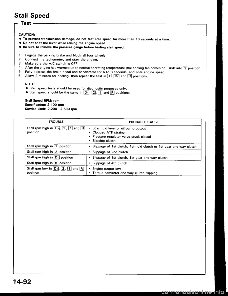
Stall Speed
CAUTION:
a To plevent transmission damage, do not test stall speed fot mote than 1O seconds at a time.a Do not shift the level while raising th€ engine speed.a Be sure to remove the pressure gauge belot€ testing stall speed.
1. Engage the parking brake and block all four wheels.
2. Connect the tachometer, and start the engine.
3. Make sure the A/C switch is OFF.
4. After the engine has warmed up to normal operating temperature (the cooling lan comes on), shift into ft position.
5. Fully depress the brake pedal and accelerator for 6 to 8 seconds. and note engine speed.6. Allow 2 minutes for cooling, then repeat the test in [, fDil and @ positions.
NOTE:
a Stall speed tests should be used lor diagnostic purposes only.. Stall speed should be the same in E, tr. tr and @ positions.
Stall Speed RPM: rpm
Specification: 2,400 rymService Limit: 2,2OO-2,600 tpm
TROUBLEPROBABLE CAUSE
Stall rpm hish in E, E, I and @posrtronLow fluid level or oil pump output
Cloqged ATF strainer
Pressure regulator valve stuck closed
Slipping clutch
Stall rpm high in I positionSlippage of 1st clutch, 1st-hold clutch or 1st gear one-way clutch
Stall rpm high in @ positionSlippage of 2nd clutch
Stall rpm high in @ positionSlippage of 1st clutch, lst gear one-way clutch
Stall rpm high in @ positionSlippage of 4th clutch
Stall rpm low in E, E, I ana @positionEngine output low
Torque converter one-way clutch slipping
14-92
Page 485 of 1413
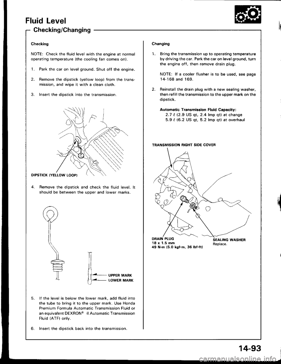
Fluid Level
Checking/Changing
Checking
NOTE: Check the fluid level with the engine at normal
operating temperature (the cooling lan comes on).
1. Park the car on level ground. Shut otf the engine.
2. Remove the dipstick (yellow loop) from the trans-
mission, and wipe it with a clean cloth.
3. Insert the dipstick into the transmission.
DIPSTICK (YELLOW LOOPI
4. Remove the dipstick and check the fluid level.
should be between the uoDer and lower marks.
P
il
\---
T
lf the level is below the lower mark, add fluid into
the tube to bring it to the upper mark. Use Honda
Premium Formula Automatic Transmission Fluid or
anequivalentDEXRON@ llAutomaticTransmission
Fluid (ATF) only.
lnse.t the diDstick back into the transmission.
IT
{J. UPPER MARK
t)-i- LowER MARK
5.
6.
Changing
1. Bring the transmission up to operating temperature
by driving the car. Park the car on level ground, turn
the engine oft, then remove drain plug.
NOTE: lf a cooler flusher is to be used, see page
14-168 and 169.
2. Reinstail the drain plug with a new sealing washer,
then refillthe transmission to the upper mark on the
dipstick.
Automatic Transmission Fluid Capacity:
2.1 | l2.S US qt, 2.4 lmp qt) at change
5.9 ? (6.2 US qt, 5.2 lmp qt) at overhaul
18 x 1.5 mm49 N.m (5.0 kgl.m, 36 lbl.ft)
TRANSMISSION RIGHT SIDE COVER
14-93
Page 486 of 1413
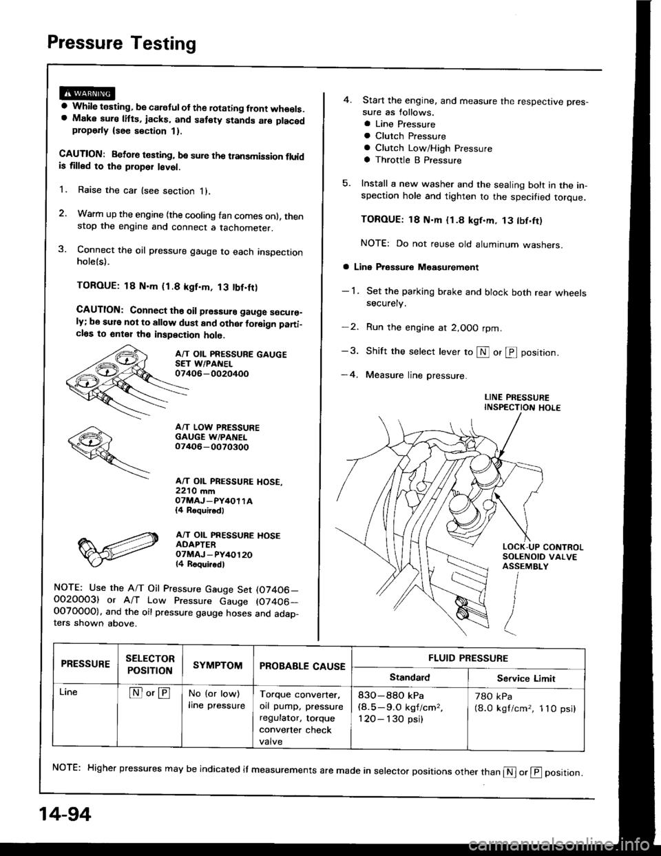
Pressure Testing
a While testing, be caretul of the rotating flont wheels.a Make aura litts, jacks, and sat€ty stands alo placedplop6rly {see section 1}.
CAUTION: Betore t€sting, be sure the transmission fluidis tilled to rh6 ploper l€vet.
1. Raise the car (see section i),
2. Warm up the engine {the cooling fan comes onl, thenstop the engine and connect a tachometer.
3. Connect the oil pressure gauge to each inspectionholels).
TOROUE: 18 N.m (1.8 kgf.m, 13 tbf.fr)
CAUTION: Connect ths oil prsssure gauge s€cur€_ly; be sule not to allow dust and other foleign pani_cl6s to 6nt€1 th€ inspection holo.
A/T OIL PRESSURE GAUGESET WPANEL07406-002oi+oo
A/T LOW PRESSUREGAUGE W/PANEL07/rO6-0O70300
A/T OIL PRESSURE HOSE,22'10 mmOTMAJ_PY4OI TA{4 Roquirod)
A/T OIL PRESSUBE HOSEADAPTEROTMAJ - PY/+O12014 Roqui.odl
NOTE: Use the A/T Oil Pressure Gauge Set (07406_O02OOO3) or A/T Low Pressure Gauge (07406-OOTO0OO). and the oil pressure gauge hoses and adap_ters shown above.
14-94
4. Start the engine, and measure the respective pres-
sure as follows.
a Line Pressure
a Clutch Pfessure
a Clutch Low/High Pressure
a Throttle B Pressure
5. Install a new washer and the sealing bolt in the in-spection hole and tighten to the specified torque.
TOROUE: 18 N'm {1.8 kgf.m, 13 tbf.ft)
NOTE: Do not reuse old aluminum washers.
a Line Pressure M€asurement
- 1 . Set the parking brake and block both rear wheelssecurely.
-2. Run the engine at 2,OOO rpm
-3. Shift the selecr lever to S or @ position.
-4. Measure line pressure.
LINE PRESSUREINSPECTION HOLE
NoTE: Higher pressures may be indicated it measurements are made in selector positions other than @ or @ position.
PRESSURESELECTOR
POStTTONSYMPTOMPROBABLE CAUSEFLUID PRESSURE
StandardService Limit
LineNo'ENo (or low)
lrne pressureTorque converter,
orl pump, pressure
regulator, to.que
convener check
valve
83O-88O kPa(8.5-9.O kgf/cm,,
120- I 30 psi)
78O kPa
{8.0 kgl/cm,, 1lO psi}
Page 487 of 1413
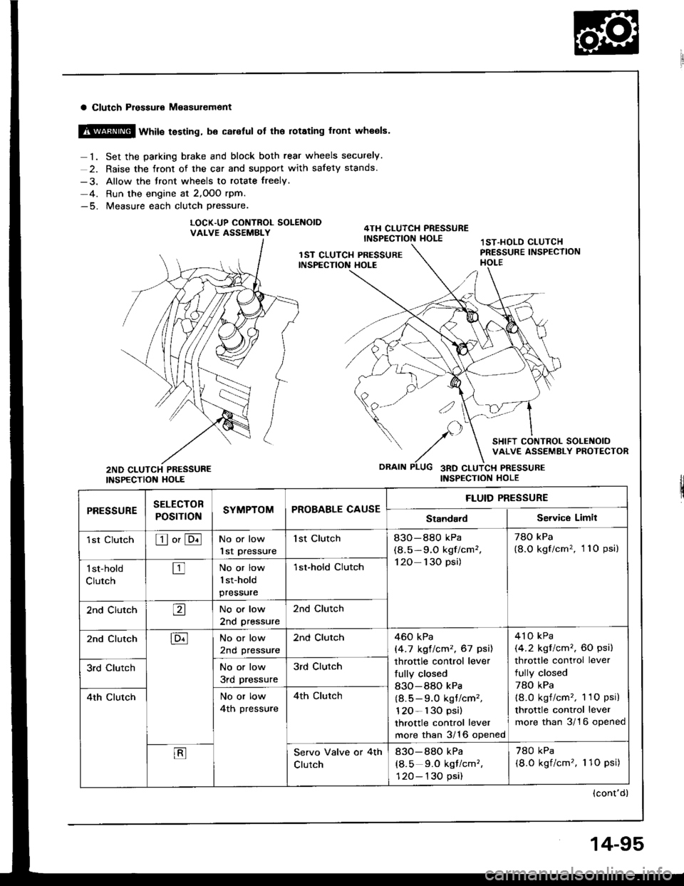
a Clutch Pressuro M€asur€ment
@ wtit" testing, be careful ot the rotating front wheols.
1. Set the parking brake and block both rear wheels securely.
2. Raise the front of the car and support with safety stands.
-3. Allow the front wheels to rotate freely,
-4. Run the engine at 2,OOO rpm.-5. Measure each clutch Pressure.
LOCK.UP CONTNOL SOLENOIDVALVE ASSEMBLY
INSPECTION HOLE
SELECTOB
POST ONSYMPTOMPROBABLE CAUSE
FLUID PRESSURE
rl|E!!UltEStandardService Limit
1st ClutchEo'ENo or low
lst Pressure
1st Clutch83O-880 kPa
(8.5-9.O kgf/cm',
120- 130 psi)
78O kPa
{8.O kgf/cm'�, 11O psi)
l st-hold
ClutchtrNo or low
1st-hold
pressure
1st-hold CIutch
2nd ClutchaNo or low
2nd pressure
2nd Clutch
2nd ClutchENo or low
2nd pressure
2nd Clutch460 kPa
|'4.7 kgt lcm2, 67 psil
throttle control lever
fully closed
830-880 kPa
(8.5 - 9.0 kgt/cm'�,
120- l30 psi)
throttle control lever
more than 3/16 opened
4'l o kPa
(4.2 kgt/cm'�, 60 psi)
throttle control lever
fully closed
78O kPa(8.O kgf/cm'�, 1 1O psi)
throttle control lever
more than 3/16 opened
3rd ClutchNo or low
3rd pressure
3rd Clutch
4th ClutchNo or low
4th pressure
4th clutch
EServo Valve or 4th
Clutch
830-880 kPa
(8.5 9.0 kqf/cm'�,
120- 130 psi)
780 kPa
(8.0 kgf/cm'�, 1 1O psi)
(cont'd)
14-95
Page 488 of 1413
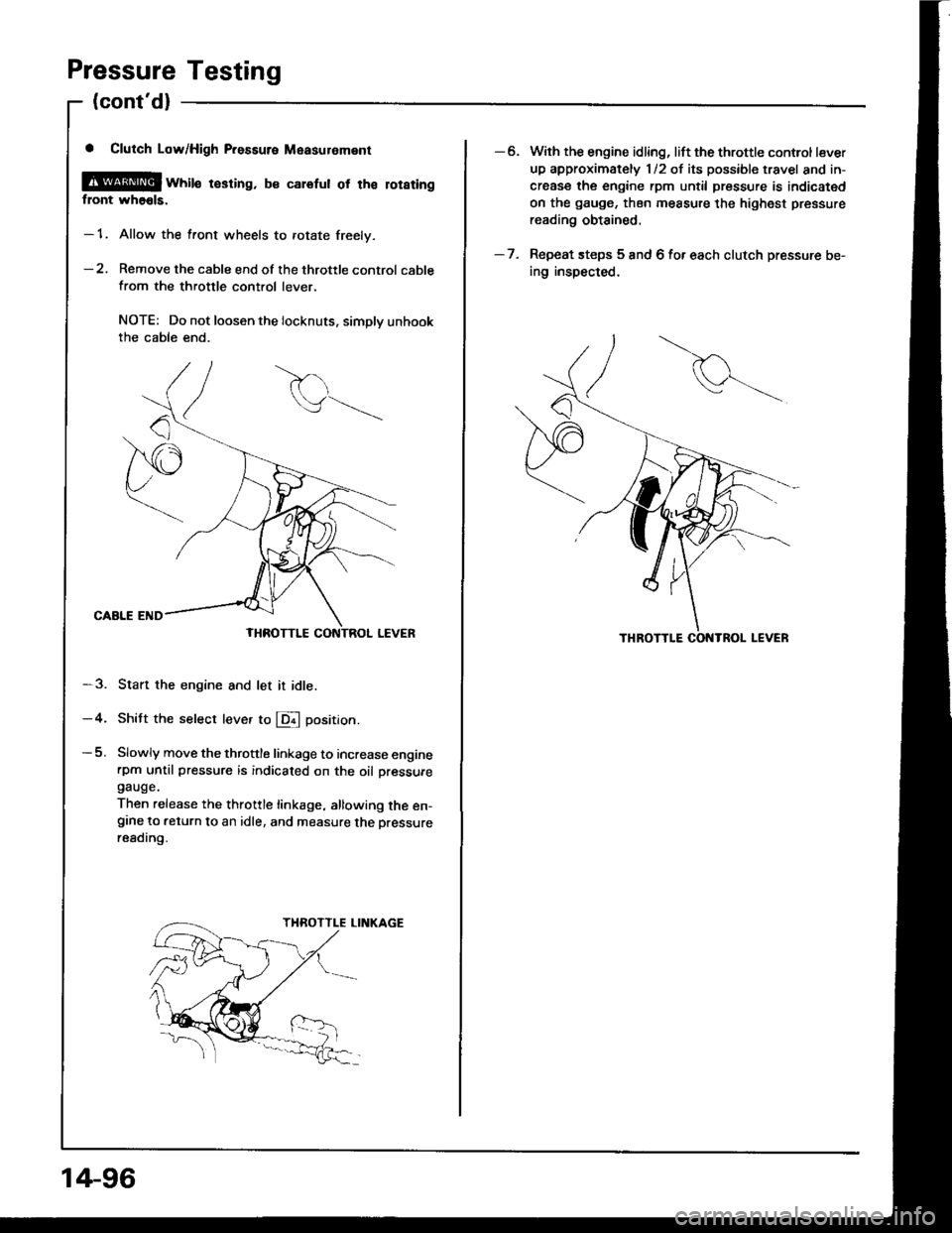
Pressure Testing
(cont'dl
a Clutch Low/High P.essure Measuroment
@[ wtite resring. b€ calefut ot tha loraringflont wh66ls.
- 1. Allow the front wheels to rotate freely.
-2. Remove the cable end of the throttle control cable
from the throttle control lever.
NOTE: Do not loosen the locknuts. simplv unhookthe cable end.
CAALE END
-3. Start the engine and let it idle.
-4. Shitt the select leve. to E position.
-5. Slowly move the throttle linkage to increase enginerpm until pressure is indicaied on the oil oressuregauge.
Then release the throttle linkage, allowing the en-grne to return to an idle, and measure the Dressureresding.
14-96
-6. With the engine idling, lift the throttle control lever
up approximately 1/2 of its possible travel and in-
crease the engine rpm until pressure is indicated
on the gauge, then measure the highest pressure
reading obtained.
- 7. Repeat steps 5 and 6 for each clutch pressure be-
ing inspected.
Page 490 of 1413
Pressure Testing
(cont'dl
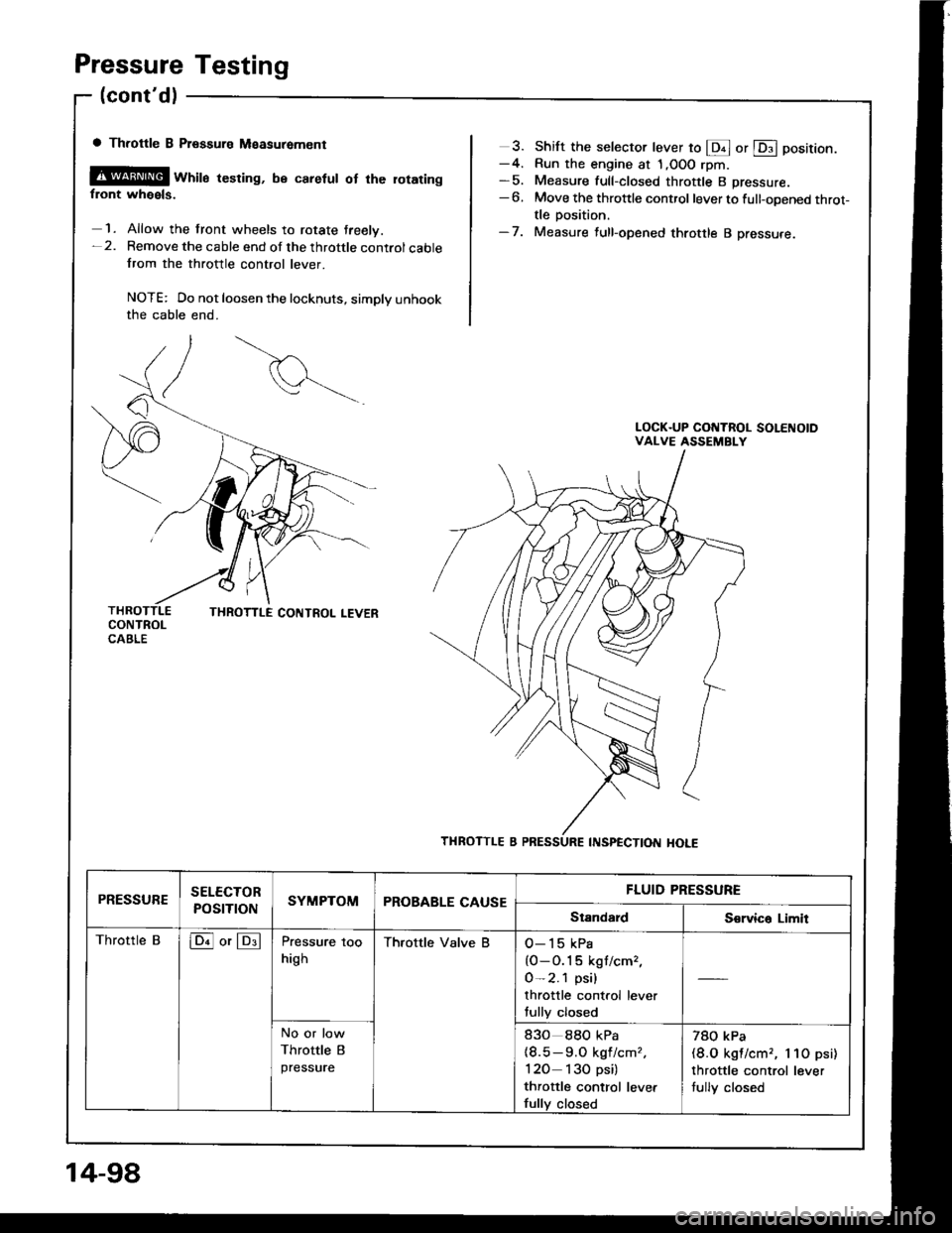
a Throttle B Ptsssure Measuremcnt
@@ wrril" resring, be caretut ot rhe rotaringfront wheels.
1. Allow the front wheels to rotate treelv.-2. Remove the cable end of the throttle controlcablefrom the throttle control lever.
NOTE: Do not loosen the locknuts, simply unhookthe cable end.
3. Shift the selector lever to @ or @ position.-4. Run the engine at 1,OOO rpm-5. Measure full-closed throttle B pressure.-6. Move the throttle control lever to full-opened throt-tle position.-7. Measure full-opened throttle B pressure.
PRESSURESELECTOR
POSTTTONSYMPTOMPROBABLE CAUSEFLUID PRESSURE
StandardS€rvica Limit
Throttle Bloil or lDllPressure too
high
Thfottle Valve BO-15 kPa
{O-O.1 5 kgf/cm,,
0-2.1 psi)
throttle control lever
fully closed
No or low
Throttle B
pressure
83o 88O kPa(8.5-9.O kgf/cmz,
120 130 psi)
thfottle control levet
fully closed
78O kPa(8.O kgl/cm,, l lO psi)
throttle control lever
tully closed
14-98
Page 493 of 1413

1 2. Pry the right driveshaft out of the differential and pry
the lett driveshatt out of the intermediate shaft.
'13. Pull on the inboard joint and remove the right and
left driveshafts (see section 16).
'14. Tie plastic bags over the driveshaft ends.
NOTE: Coat all precision finished surfaces with
clean engine oil.
PLASTIC BAG
Disconnect the heated oxygen sensor (HO2S) con-
necror.
Remove the exhaust pipe A.16.
SELF-LOCKINGNUTReplace.
Replace.
14-101
17. Remove the intermediate shaft.
Remove the shift cable cover, then remove the shift
cable by removing the control lever.
CAUTION: Take care not to bend the shift control
cabls whilo removing it.
18.
SHIFT CABLE
LOCKWASHER CONTROLLEVERReplace.
(cont'dl
Page 494 of 1413
Transmission
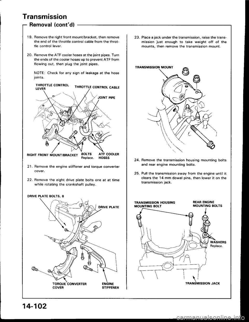
Removal (cont'dl
'1 9.Remove the right tront mount/bracket, then remove
the end ol the throttle cont.ol cable trom the throt-
tle control lever.
Remove the ATF cooler hoses at the joint pipes. Turn
the ends of the cooler hoses up to prevent ATF from
flowing out, then plug the joint pipes.
NOTE: Check tor any sign ot leakage at the hosejoints.
THROTTLE CONTROL
23. Place a jack under the transmission, raise the lrans-
mission just enough to take weight off ol the
mounts. then remove the transmission mount.
20.
RrcHT FRoNT iiouNT/BRAcKET BoLTsATF COOLERHOSESReplace.24. Remove the t.ansmission housing mounting bolts
and rear engine mounting bolts.
25. Pull the transmission away from the engine until it
clears the 14 mm dowel Dins, then lower it on the
transmission iack.
21. Remove the engine stiftener and totque converter
cover.
22. Remove the eight drive plate bolts one at at time
while rotating the crankshaft pulley.
WASHERSReplace.
'i z/'l e
" (-J t'
14-102
Page 554 of 1413
Transmission
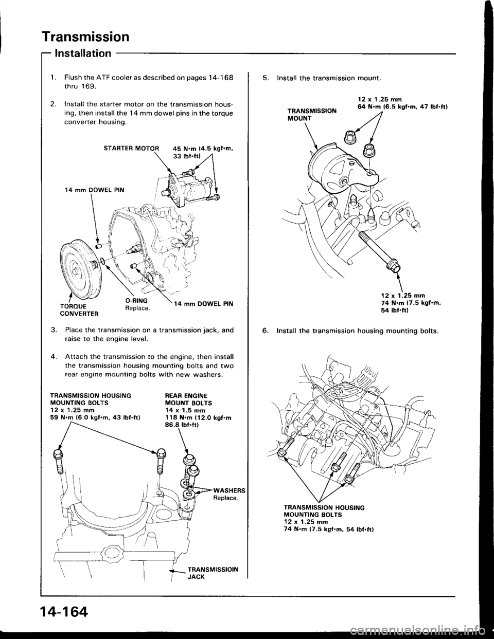
Installation
1. Flush the ATF cooler as described on pages I4-168
thru 'l 69.
2. Install the starter motor on the transmission hous-
ing, then installthe l4 mm dowel pins in the torque
converrer nousrng.
STARTER MOTOR
O-RINGReplace.14 mm OOWEL PINTOROUECONVERTER
J.
TRANSMISSION HOUSINGMOUNTING BOLTS
59 N.m 16.0 kgf.m,43 lbl.ftl
Place the transmission on a transmission jack, and
raise to the engine level.
Attach the transmission to the engine, then install
the transmission housing mounting bolts and two
rear engine mounting bolts with new washers.
REAR ENGINEMOUNT BOLTS14 x 1.5 mm
45 N.m 14.5 kgf'm,
'14 mm DOWEL PIN
I
i.'l,i;
14-164
5. Install the transmission mount.
6. Install the transmission
12 x 1.25 mm64 N.m 16.5 kgl.m, 47 lbf.ft)
12 x 1.25 mm74 N.m 17.5 kgf'm,54 rbt'ft)
housing mounting bolts.
MOUNTING BOLTS12 x 1 .25 rnm74 N.m (7.5 kgf'm, 54 lbf.ftl
TRANSMISSION HOUSING