engine ACURA INTEGRA 1994 Service Repair Manual
[x] Cancel search | Manufacturer: ACURA, Model Year: 1994, Model line: INTEGRA, Model: ACURA INTEGRA 1994Pages: 1413, PDF Size: 37.94 MB
Page 575 of 1413
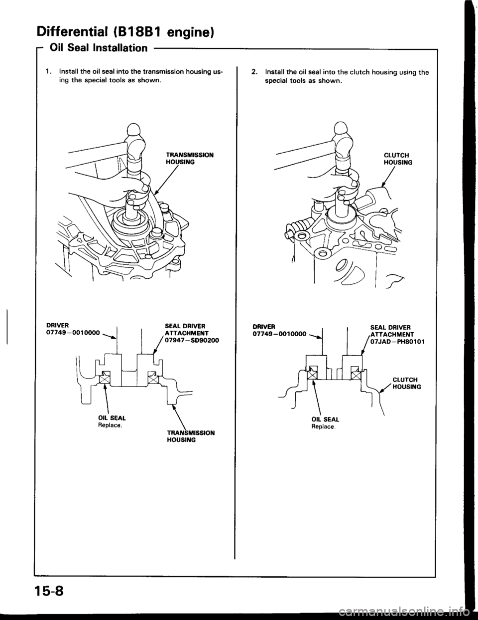
Differential (81 88l enginel
Oil Seal Installation
1. Install the oil seal into the t.ansmission housing us-
ing the special tools as shown
DRIVER07749-0010000
OIL SEALReplsce.
HOUSING
15-8
Install the oil seal into the clutch housing using the
soecial tools as shown.
DRIVER07749-0010000
OIL SEALReplace.
Page 576 of 1413
Differential (818C1 enginel
Special Tools ........
Differential
lllustrated Index .........
Backlash Inspection
Final Driven Gear Replacement ......
Tapered Roller Bearing Replacement.
Oil Seal Removal
Bearing Outer Race Replacement ...
Tapered Roller Bearing Preload
Adjustment
Oil Seal Installation
1 5-10
15-1 1
15-12
15-12
15-13
15-13
15-14
15-15
15-17
Page 578 of 1413
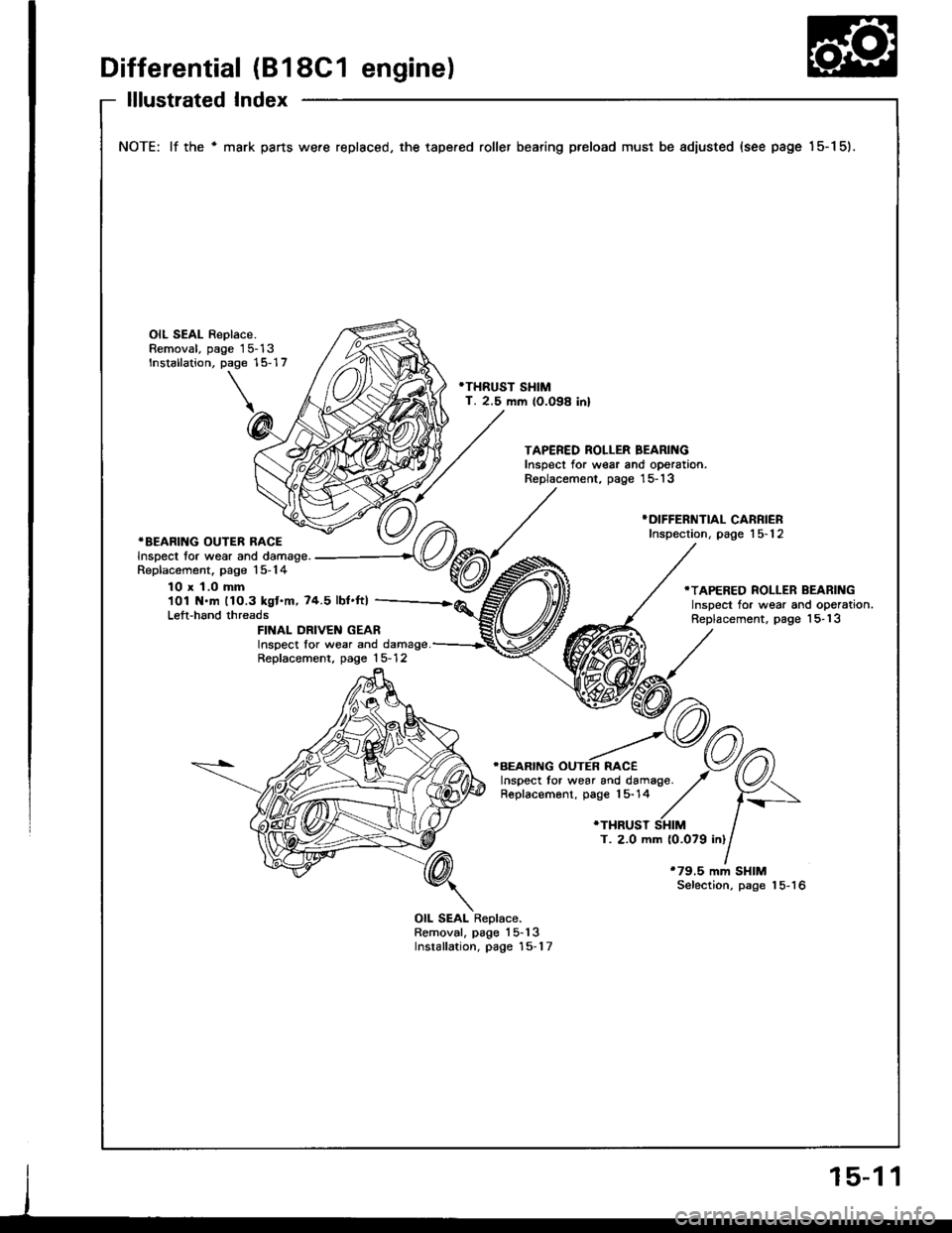
Differential (B18C1 engine)
lllustrated Index
NOTE: lf the ' mark parts were replaced, the tape.ed roller bearing preload must be adiusted (see page 15-1 5).
OIL SEAL Replace.Removal, page 15-13Installation, page 15-17
'THRUST SHIMT. 2.5 mm lO.O98 inl
TAPERED ROLLER BEARINGInspect for wear and oporation.Replacement, page '15- 13
*BEARING OUTER RACEInspect tor wear and damage.Replacement. page 15-14
}DIFFERNTIAL CARRIERInspection, page 15-12
10 x 1.0 mm101 N.m 11O.3 kgt.m,74.5 lbt.ft)Left-hand threads
.TAPERED ROLLER BEARINGInspect for wear and operation.Replacement, page 'l5- 13FINAL DRIVEN GEARInspect lor wear and damage.Replacement, page 15- 12
T. 2.0 mm (0.079 inl
*79.5 mm SHIMSelection, page 15-16
OIL SEAL Replace.Removal, page'l5-13Installation, page 15-1 7
Page 579 of 1413
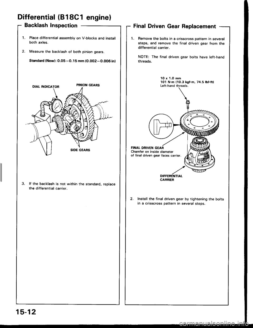
Differential (818C1 enginel
Backlash Inspection
Place ditterential assembly on V-btocks and instatlboth axles.
Measure the backlash of both pinion gears.
Standard (Now): 0.o5-o.15 mm {0.oo2-0.O06 in)
lf the backlash is not within the standard, reDlacethe differential carrier,
Final Driven Gear Replacement
1. Romove the bolts in a crisscross Dattern in several
steps, and remove the tinal driven gear f.om thedifferential carrier.
NOTE: The tinal driven gear bolts have lett-hand
threads.
10 x 1.O mm101 N.m (10.3 kgt.m, 74.5 lbf.ftlLeft-hand threads.
FII{AL DN|VEN GEARChamfer on inside diameterof linal driven g€ar taces carrier.
DIFFERETTTIALCABRIER
Install the final driven gear by tightening the bolts
in a crisscross pattern in several steps.
15-12
Page 583 of 1413
Differential (B18C1 enginel
Tapered Roller Bearing Preload Adjustment (cont'dl
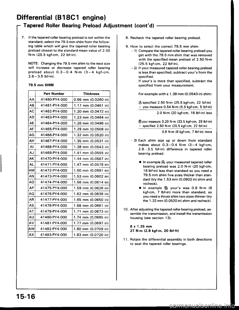
7. It the tapered roller bearing preload is not within the
standard, select the 79.5 mm shim lrom the follow-
ing table which will give the tapered roller bea.ing
preload closest to the standard mean value of 2.50
N.m (25.5 kgJ.cm, 22 lbf.in).
NOTE: Changing the 79.5 mm shim to the next size
will increase or decrease tapered roller bearing
preload about O.3-O.4 N.m (3-4 kgf.cm,
2.6 - 3.5 lbt.in).
79.5 mm SHIM
Part NumbelThickness
41460-PY4-0000.66 mm (0.0260 in)
AB41461-PY4-0001.17 mm (O.0461In,
AC41462-PY4-0001 .2O mm (0.0472 in)
AD41463-PY4-0001.23 mm (O.O484 in)
AE41464-PY4-0001.26 mm (0.0496 in)
AF41465-PY4-OOO1.29 mm (O.O5O8 in)
AG41466-PY4-OOO1.32 mm (O.O52O in)
AH41 467-PY4-0001.35 mm {O.O531 in)
AI41468-PY4-0001.38 mm (O.O543 in)
AJ41469-PY4-0001 .41 mm (O.0555 in)
AK41470-PY4-OOO1 .44 mm (0.0567 in)
AL41 47 1 -PY 4-OOO1 .47 mm (0.0579 in)
AM41 47 2-PY 4-OOO1.50 mm {O.O591 in)
AN41473-PY4-0001 .53 mm (0.0602 in)
AO41 47 4-PY 4-OOO1.56 mm (0.0614 in)
AP41475-PY4-OOO'l .59 mm (O.0626 in)
AO4'1476-PY4-O001.62 mm (0.0638 in)
AR41 47 7 -PY 4-OOO1 .65 mm (0.0650 in)
AS41478-PY4-0001 .68 mm {0.0661 in)
41479-PY4-OOO1.71 mm (O.0673 in)
AU41480-PY4-OOO1.74 mm (0.0685 in)
41481-PY4-OOO1 .77 mm {0.0697 in}
41442-PY4-OOO1.80 mm (O.O7O9 in)
AX41483-PY4-OOO1.83 mm (0.0720 inl
15-16
9.
Recheck the tapered roller bearing preload.
How to select the correct 79.5 mm shim:- 1) Compare the tapered roller bearing preload you
get with the 79.5 mm shim that was removed
with the specified mean preload of 2.50 N.m(25.5 kgf .cm. 22 lbf.inl.-2) lf your measured tapered roller bearing preload
is less than specified, subtract your's from the
soecified.
lf your's is more than specified, subtract the
specified from your measurement.
For example with a 1 .38 mm (O.O543 in) shim:
@ specified 2.50 N.m (25.5 kgf.cm, 22 lbf.in)- you measure 0.54 N.m (5.5 kgt.cm, 5lbt'in)
2.0 N.m {20 kgf.cm, 18lbt.in} less
@you measure 3.29 N.m {33.5 kgl.cm, 29 lbl.in)- specified 2.50 N.m {25.5 kgf.cm, 22 lbf.in)
0.8 N.m (8 kgf.cm, 7lbt.in) more
3) Each shim size uD or down from standard
makes about O.3-O.4 N.m (3-4 kgf.cm,
2.6-3.5 lbf.in) difJerence in tapered roller
bearing preload.
a In example @, your measured tapered roller
bearing preload was 2.O N.m (20 kgf'cm,
I 8 lbl.in) less than standard so you need a
79.5 mm shim five sizes thicker thsn stan-
dard {trv the 1.53 mm (0.0602 inl shim and
recheck).
a In example @ your's was O.8 N.m (8
kgf.cm, 7 lbJ.in) more than standard, so
you need a thrust shim two sizes thinner (try
the 1.32 mm (0.0520 in) shim and recheck).
After adjusting the tapered .oller bearing preload, as-
semble the transmission, and installthe transmission
housing {see section 13).
8 x 1.25 mm
27 N.m 12.8 kgt.m. 20 lbf.ttl
Rotate the diJJerential assemblv in both directions
to seat the tapered roller bearings.
10.
11.
Page 611 of 1413
System Description
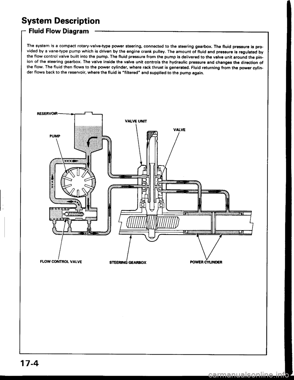
Fluid Flow Diagram
The system is a compact rotary-valvs-type power stssring, connocted to the st€oring gearbox. Th6 fluid pressure is pro-vided by a vane-type pump which is driven by the engine crank pulley. The amount of fluid and pressurs is regulsted bythe flow control valve built into ths pump, The fluid prssaurs from th6 pump is dolivsred to tho valve unit sround the pin-ion of the steering g€arbox. The vslv€ inside the valvs unit controls the hydraulic prossur€ End changos the direction otthe flow. The fluid then flows to the power cylinder, where rack thrust is gen6rat6d. Fluid returning from th6 powsr cylin-der flows back to the .eservoir, where the fluid is 'filtered" and supplied to the pump Egain.
17-4
Page 613 of 1413
System Description
Steering Pump (cont'dl
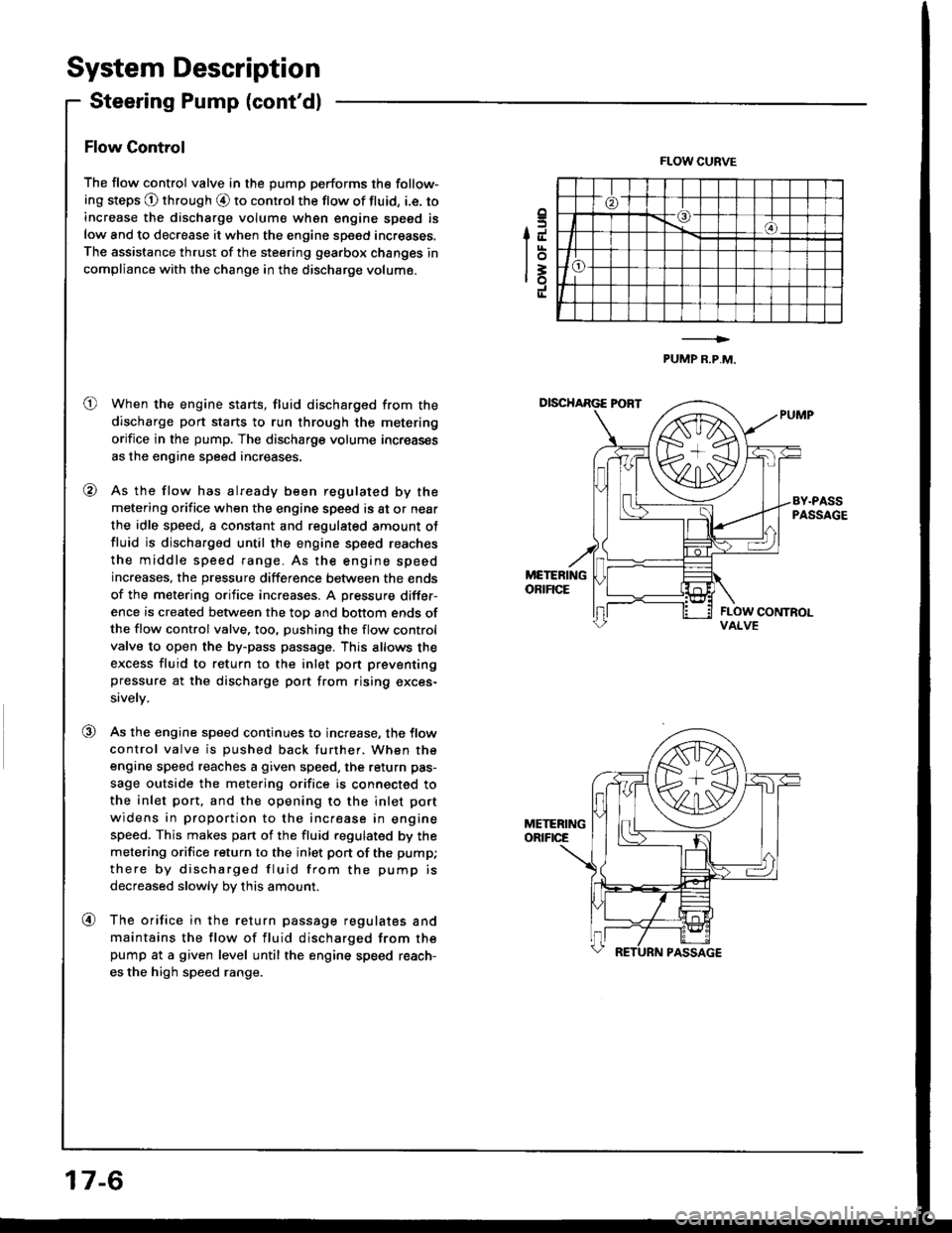
Flow Control
The flow control valve in the pump performs the follow-
ing steps @ through O to control the flow of fluid, i.e. to
increase the discharge volum€ wh6n engine speed is
low and to decrease it when the engine speed increases.
The assistance thrust of the steering gearbox changes in
compliance with the change in the discharge volume.
When the engine starts, fluid discharged from the
discharge port starts to run through the metering
orifice in the pump. The discharge volume increas€s
as the engine speed increases,
As the flow has already been regulated by the
metering orifice when the engine speed is at or near
the idle speed, a constant and regulated amount ot
fluid is discharged until the engine speed reaches
the middle speed range. As the engine speed
increases, the pressure difference between the ends
of the metering orifice increases. A pressure differ-
ence is created between the top and bottom ends ofthe flow control valve, too, pushing the flow control
valve to open the by-pass passage. This allows the
excess fluid to return to the inlet pon preventing
pressure at the discharge port trom rising exces-
sively.
As the engine speed continues to increase, the tlow
control valve is pushed back further. When the
engine speed reaches a given speed. the return pas-
sage outside the metering orifice is connected to
the inlet port, and the opening to the inlet port
widens in proportion to the increase in engine
speed. This makes pan of the fluid regulated by the
metering orifice return to the inlet pon of the pump;
there by discharged fluid from the pump is
decreased slowly by this amount.
The orifice in the return passage regulates and
maintains the flow of fluid discharged from thepump at a given level until the engine speed reach-
es the high speed range.
.5IJ
lot=ro
FLOW CURVE
PUMP R.P,M.
o
@
VALVE
@
@
17-6
Page 617 of 1413
Troubleshooting
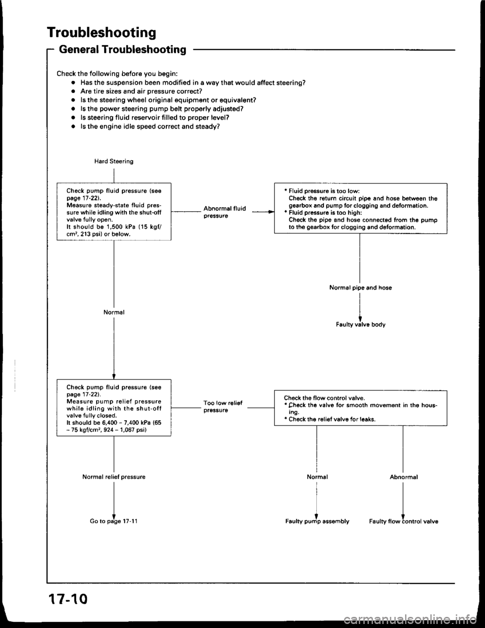
General Troubleshooting
Check the following betore you begin:
. Has the susp€nsion been modified in a way that would affect steering?. Are tire sizes and air pressure correct?
. ls the steering whe€l original squipment or equivalent?
. ls the power steering pump belt properly adiusted?
o ls steering fluid reservoir filled to proper level?
o ls the engine idle speed correct and steady?
Normal reliel pressure
I
I
Go to pate tu.l t
r Fluid pro$ure is too low:Chock th€ rgturn circuit pipe and hose between thogearbox and pump tor clogging and dotormation.* Fluid pressure is too hioh:Check the pipe and hosg connected from th6 pumpto tho georbox tor clogging and delormation.
Check pump fluid pressurg (soepage 17-221,Measure steady-state fluid pres-sure while idling with the shut-offvalve fully open.Ir shoutd be 1,500 kPa (15 kgtcm'�, 213 psi) or bolow.
Normal
Check pump fluid pr€ssur€ {se€page 17-221.Measure pump relief pressurewhile idling with the shut-offvalve fully closod.h should be 6,400 - 7,400 kPa {65- 75 kgtcm,, 924 - 1,067 psi)
Check the flow control valve.* Check lhe valve for smooth movement in thg hou6-Ing.* Chock thg reli€f valve for leaks.
Abnormal
I
I
Faulty flowtontroi valve
17-10
Page 618 of 1413
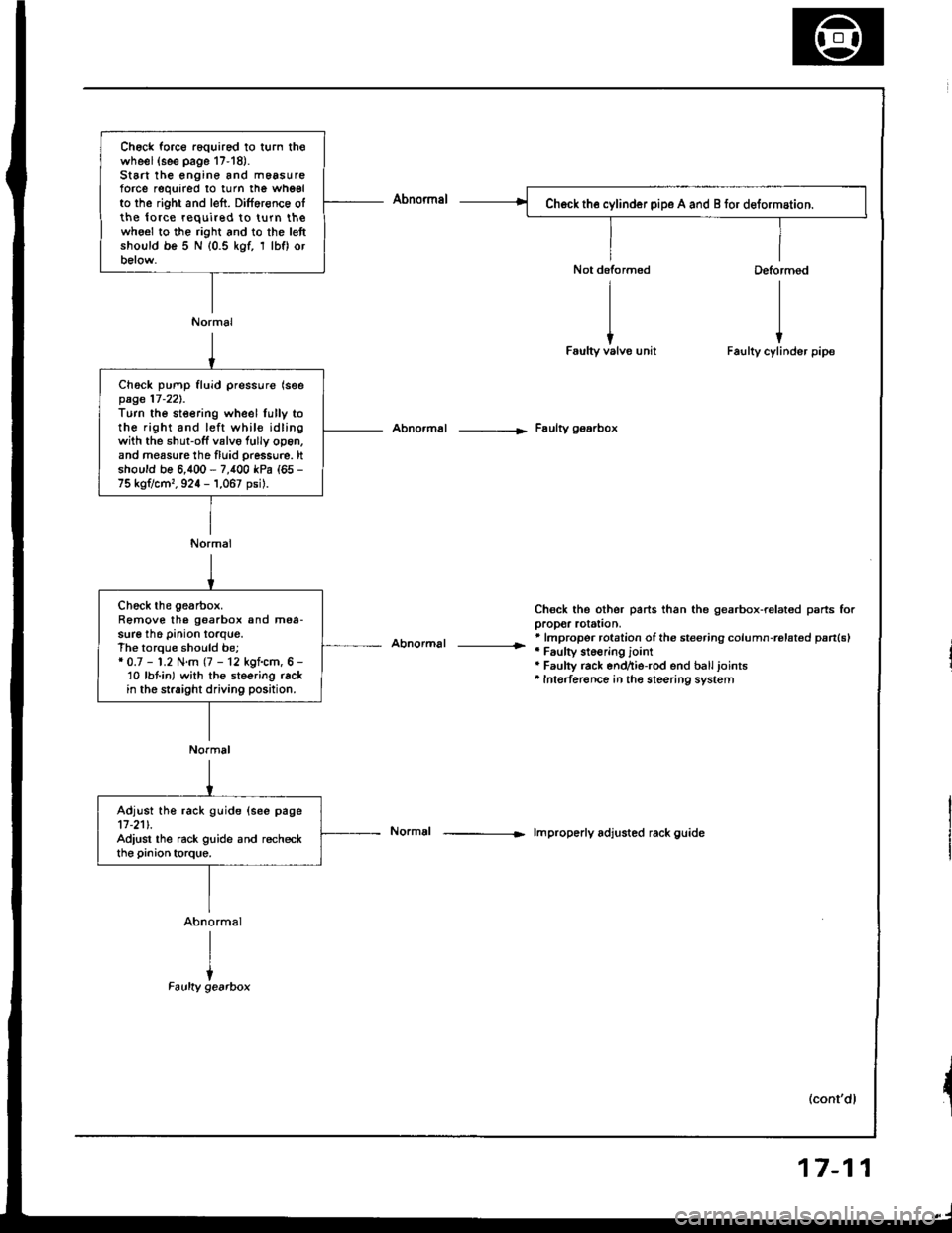
Ch6ck force r6quired to turn thowheel(see page 17-18).St6 the engine and m6asureforce required to turn the whgelto the right and left. Dilference olthe lo.ce required to turn thewho€l to the right and to the lettshould be 5 N (0.5 kgf, 1 lbf) orbelow.
Normal
Ch6ck pump fluid pressure (seepage 17-221.Turn the steering wheel lully tothe right and left whil€ idlingwith the shut-off valvo fully op6n,and measure tho fluid pressu.e. ltshould be 6,400 - 7,400 kPa (65 -
75 kg?cm,, 924 - 1,067 psil.
Normal
Abnormal -----|. Faulty gearbox
Abnormal |r
Chsck the other parts than the gearbox-ralated psrts forpropor rotstion,* lmpropor rotation ofthe steering column-rolat€d pan(sl'Faulty st6€ring jointa Faulty rack end^ie-rod end balljoints'Intederence in the steering system
lmproperly adjusted rack guide
(cont'dl
Chock the gearbox.Remove the goarbox and mea-sure the pinion torque.The torque should be;* 0.7 - 1.2 N.m (7 - 12 kgf.cm, 6 -'10 lbt in) with the steering rackin the straight driving position.
Normal
Adjust the rack guide (see page11-211.Adiust the rack guide and recheckthe pinion torque.
17-11
Page 621 of 1413
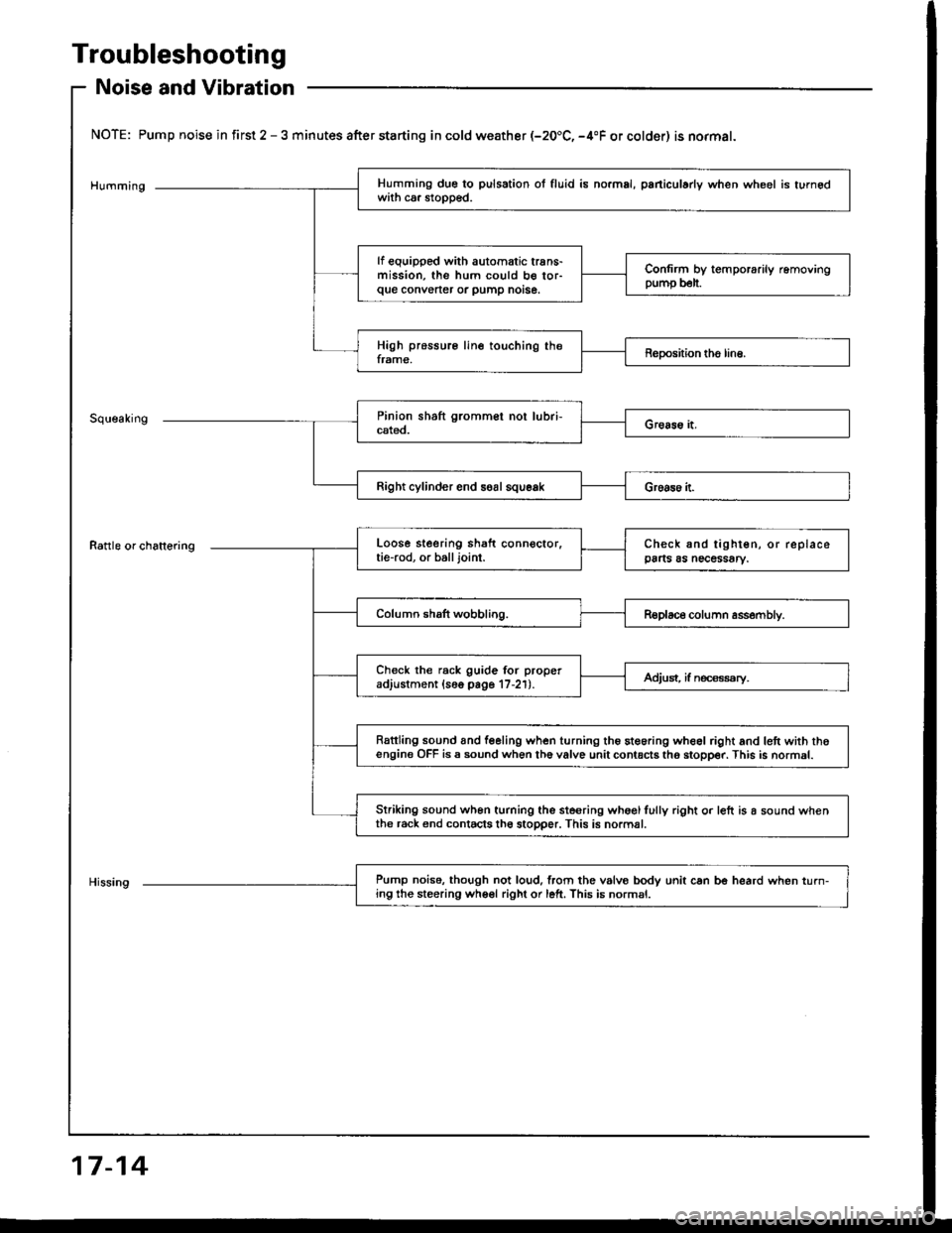
Troubleshooting
Noise and Vibration
NOTE: Pump noise in first 2 - 3 minutes after starting in cold weather (-20.C, -4"F or colder) is normal.
Humming
Rattle or chattering
Right cylinder end soal squeak
Pump noise. though not loud,lrom the vslvo bodv unit can be heard when turn-ing the steering wheel right or left. This is normsl.
Humming due to pulsation ol fluid is no.mal, paniculady when wheel is turnedwith ca. stopped.
lf equipped with automatic trans-mission, the hum could b€ tor-que convener or pump notse.
Confirm by temporarily removingpump b€lt.
High pressure line touching theframe,Reposhion tho line.
Loose steering shaft connector.tie-rod, or balljoint.Check and tighten, or replacepa s as necessary.
Column shaft wobbling.Replace column assembly.
Check the rack guide for properadjustment (16o page 17-21).Adjust, if n€ca€ssry.
Rattling sound and feeling when turning the steoring wheel right and lett with thoengine OFF is a sound when th6 valve unit contacts tho stopper. This is normal.
Striking sound wh6n turning the ste€ring whoglfully right o. left is a sound whenthe r6ck end contacts th6 stopper. This is normal.
17-14