ACURA INTEGRA 1994 Service Repair Manual
INTEGRA 1994
ACURA
ACURA
https://www.carmanualsonline.info/img/32/56982/w960_56982-0.png
ACURA INTEGRA 1994 Service Repair Manual
Trending: tires, center console, fuel, wiper, fuse, Circuit, coolant temperature
Page 401 of 1413
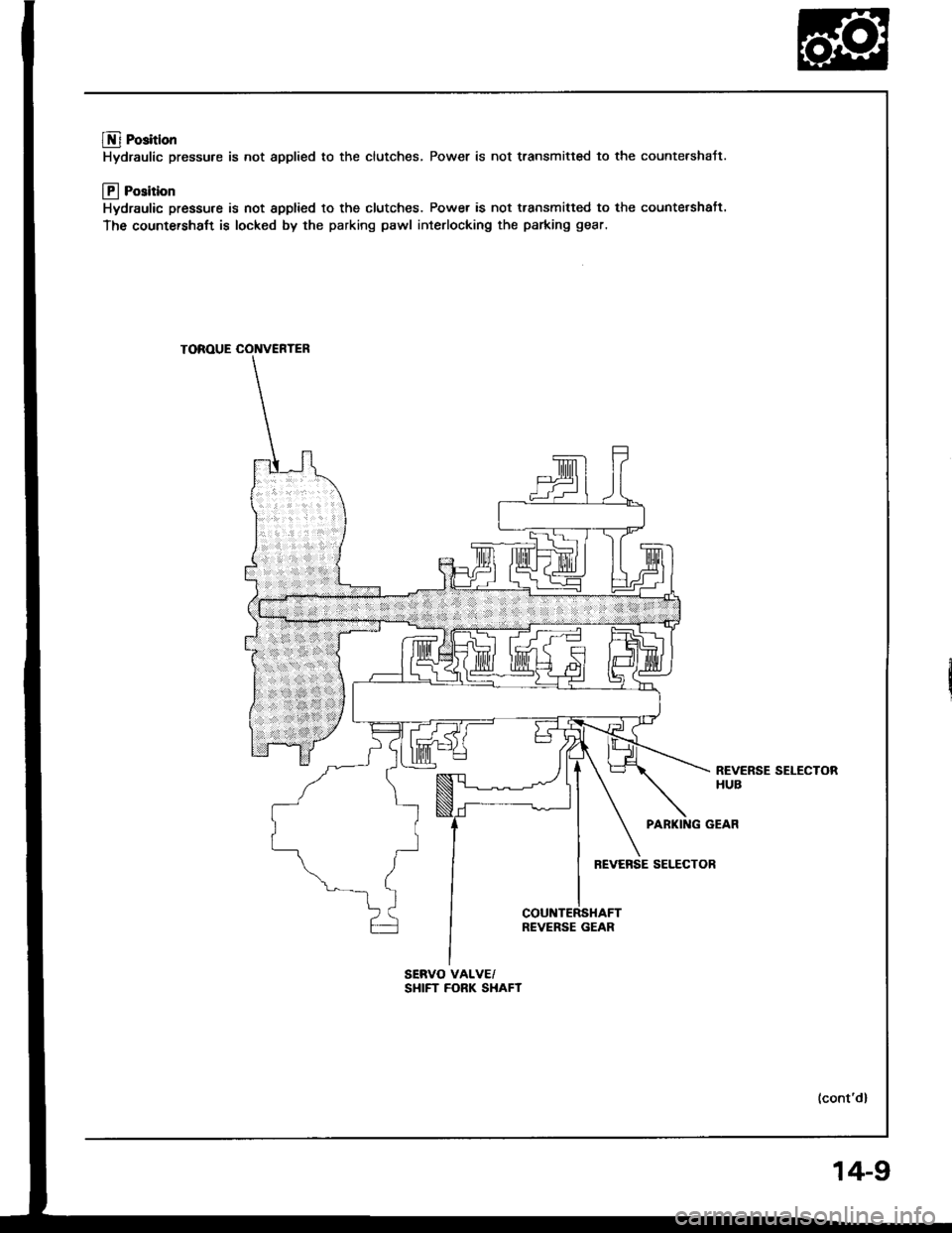
@ Position
Hydraulic pressure is not applied to the clutches, Power is not transmitted to the countershaJt.
@ Position
Hydraulic pressure is not spplied to the clutches. Power is not transmitted to the countetshaft.
The countersha{t is locked by the parking pawl interlocking the parking gear.
TOROUE CONVERTER
PARKING GEAR
REVERSE SELECTOR
REVERSE GEAR
REVERSE SELECTORHUB
SERVO VALVE/SHIFT FORK SHAFT
14-9
Page 402 of 1413
Description
Power Flow lcont'dl
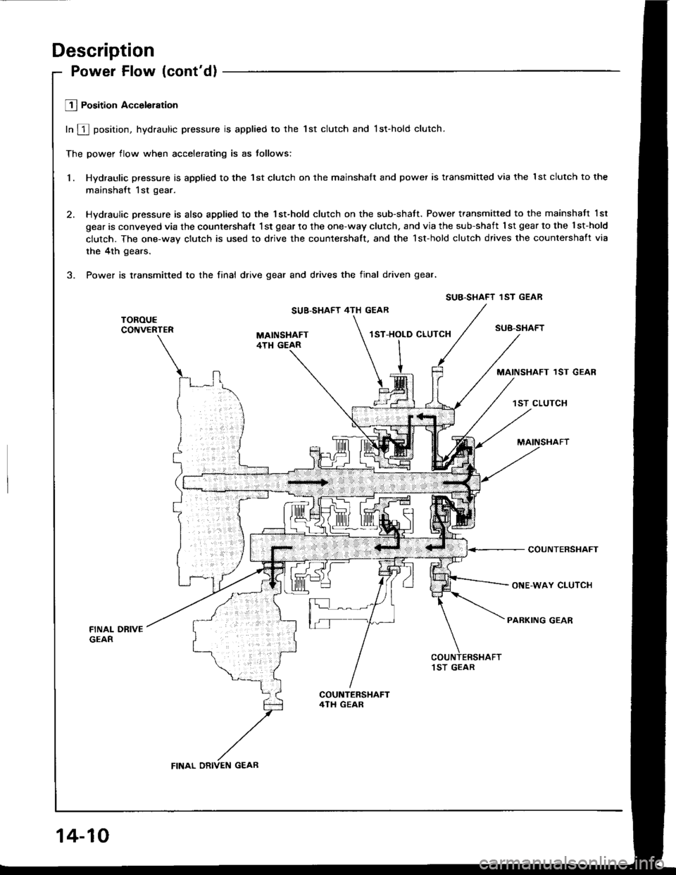
Lll Position Acceloration
In f position, hydraulic pressure is applied to the lst clutch and lst-hold clutch.
The power flow when accelerating is as tollows:
1. Hydraulic pressure is applied to the 1st clutch on the mainshalt and power is transmitted via the lst clutch to the
mainshaft 1st gear.
2. Hydraulic pressure is also applied to the 1st-hold clutch on the sub-shatt. Power transmitted to the mainshaft 1sl
gear is conveyed via the countershaft 1st gear to the one-way clutch. and via the sub-shaft 1 st gear to the l st-hold
clutch. The one-way clutch is used to drive the countershaft. and the 1st-hold clutch drives the countershaft via
the 4th gears.
3. Power is transmitted to the finai drive gear and drives the final d.iven gear,
SUB-SHAFT 4TH GEAR
SUB-SHAFTlST-HOLD CLUTCH
MAINSHAFT 1ST GEAR
1ST CLUTCH
COUNTERSHAFT
ONE-WAY CLUTCH
PARKING GEAR
,I ST GEAR
SUB.SHAFT 'IST GEAR
FINAL DRIVEN GEAR
14-10
Page 403 of 1413
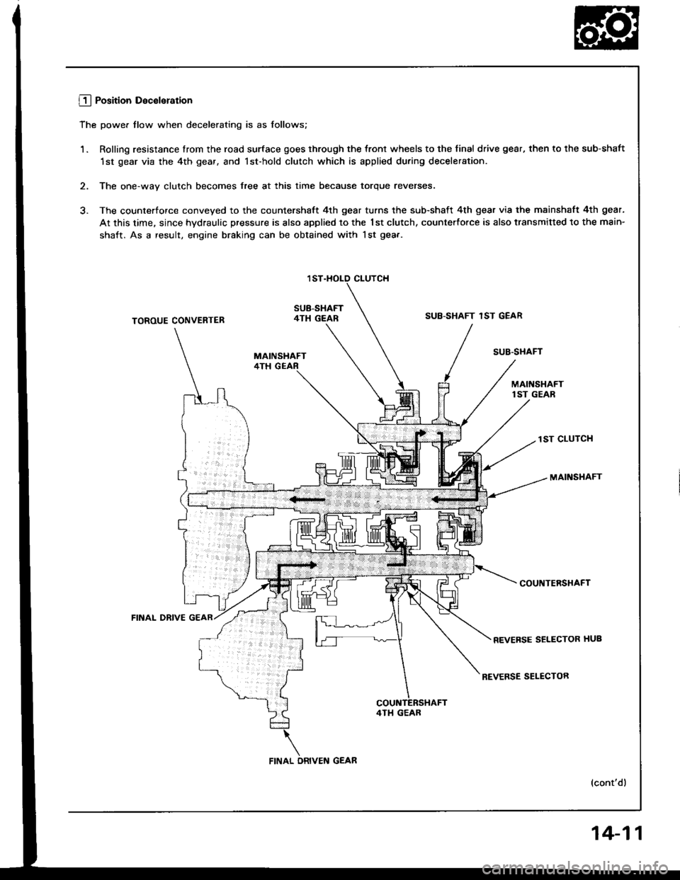
L!_j Position Deceleration
The power tlow when decelerating is as follows;
1. Rolling resistance lrom the road surface goes through the tront wheels to the final drive gear, then to the sub-shaft
1st gear via the 4th gear, and lst-hold clutch which is applied during deceleration.
2. The one-way clutch becomes free at this time because torque reverses.
3. The counterforce conveyed to the countershaft 4th gear turns the sub-shaft 4th gear via the mainshaft 4th gear.
At this time, since hydraulic pressure is also applied to the 1st clutch, counterfo.ce is also transmitted to the main-
shaft. As a result, engine braking can be obtained with lst gea.-
CLUTCH
SUB-SHAFT4TH GEARSUB-SHAFT 1ST GEARTOROUE CONVENTER
FINAL DRIVE
SUB'STIAFT
lST CLUTCH
MAINSHAFT
COUNTERSHAFT
REVEFSE SELECTOR HUB
REVERSE SELECTOR
(cont'dl
4TI1 GEAB
14-11
Page 404 of 1413
Description
Power Flow (cont'd)
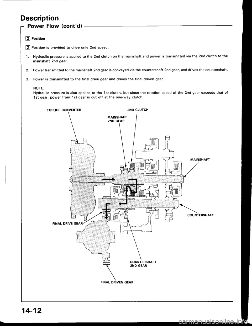
Ll Position
@ Position is provided to drive only 2nd speed.
1. Hydraulic pressure is applied to the 2nd clutch on the mainshatt and power is transmitted via the 2nd clutch to the
mainshaft 2nd gear.
2. Power transmitted to the mainshalt 2nd gear is conveyed via the countershaft 2nd gear, and drives the countersha{t.
3. Power is transmitted to the final drive gear and drives the final driven gear.
NOTE:
Hydraulic pressure is also applied to the lst clutch, but since the rotation speed of the 2nd gear exceeds that of
1st gear, power from 1st gear is cut off at the one-way clutch.
TOROUE CONVERTER2ND CLUTCH
MAINSHAFT
COUNTERSHAFT
FINAL DBIVE
2ND GEAR
FINAL DRIVEN GEAR
14-12
Page 405 of 1413
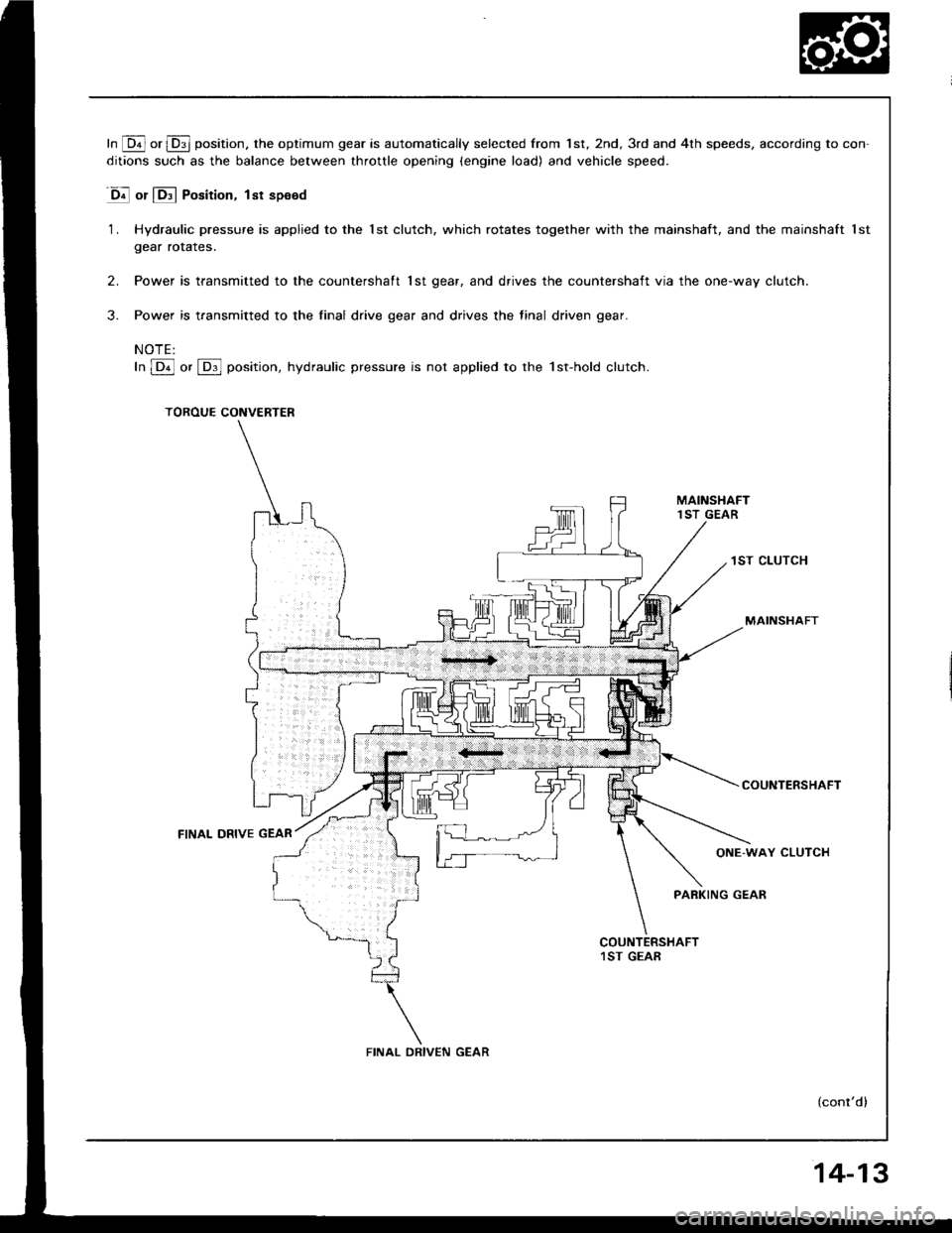
In [Q! or l!31 position. the optimum gear is automatically selected from 1st, 2nd, 3rd and 4th speeds, according to con-
ditions such as the balance between throttle opening (engine load) and vehicle speed.
D! or lE.l Position, lst speed
1. Hydraulic pressure is applied to the lst clutch. which rotates together with the mainshaft, and the mainshaft lst
gear rorares.
2. Power is transmitted to the countershaft 1st gear, and drives the countershaft via the one-way clutch.
3. Power is transmitted to the final drive gear and drives the final driven gear.
NOTE:
In lDil or [Dl]l position, hydraulic pressure is not applied to the 1st-hold clutch.
TOROUE CONVERTER
1ST CLUTCH
MAINSHAFT
COUNTERSHAFT
(cont'd)
FINAL DRIVE GEAR
FINAL DRIVEN GEAR
14-13
Page 406 of 1413
Description
Power Flow (cont'd)
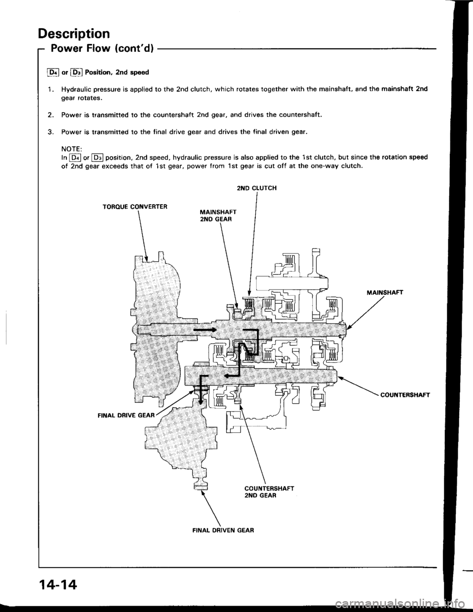
JD.l or lD"l Position, 2nd speed
1. Hydraulic pressure is applied to the 2nd clutch, which rotates together with the mainshaft, and the mainshatt 2nd
gear rotates.
2. Power is transmitted to the countershaft 2nd gear, and drives the countershaft.
3. Power is transmitted to the tinal drive gear and drives the final driven gear.
NOTE:
In @ or @ position, 2nd speed, hydraulic pressure is also applied to the lst clutch. but since the rotation speed
of 2nd gear exceeds that of 1st gear. power trom lst gear is cut off at the one-way clutch.
TOROUE CONVERTER
MAINSHAFT
COUNTERSHAFT
FINAL DRIVE GEAR
2ND CLUTCH
FINAL DRIVEN GEAR
14-14
Page 407 of 1413
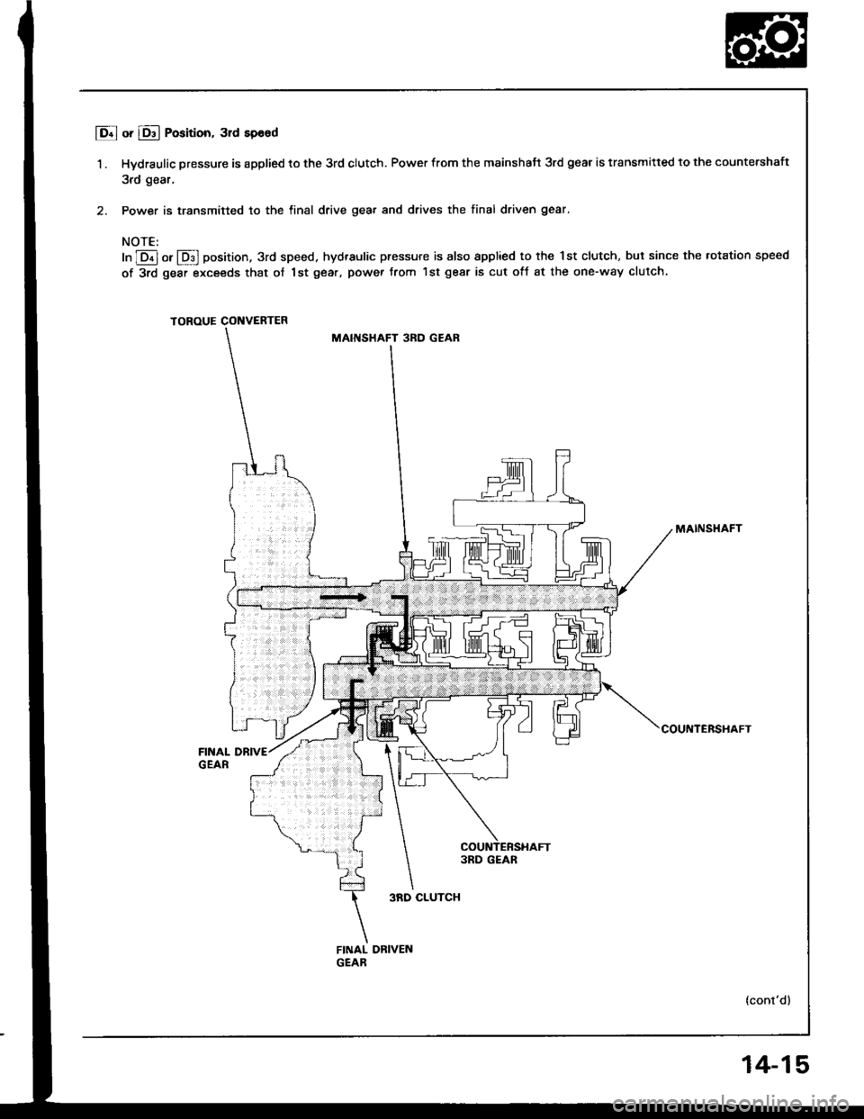
I o.l or 16ll Position, 31d sp€od
1 . Hydraulic pressure is applied to the 3rd clutch. Power from the mainshatt 3rd gear is transmitted to the countershaft
3rd gear,
2. Power is transmitted to the tinal drive geat and drives the final driven gear.
NOTE:
In ]Dil or lDJl position. 3rd speed. hydraulic pressure is also applied to the Ist clutch, but since the rotation speed
of 3rd gear exceeds that of 1st gear, power trom lst gear is cut ofJ at the one-way clutch,
TOROUE CONVERTER
MAINSHAFT 3RD GEAR
MAINSHAFT
COUNTERSHAFT
FINAL DRIVEGEAR
3RD CLUTCH
FINAL DBIVENGEAR
14-15
Page 408 of 1413
Description
Power Flow (cont'dl
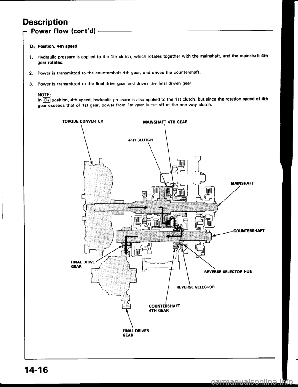
E Poshion. 4th sp6od
1. Hydraulic pressure is applied to the 4th clutch, which rotates together with the mainshatt, and th€ mainshaft 4th
gear rotates.
2. Power is transmifted to the countershaft 4th gear, and drives the countershaj-t.
3. Power is transmitted to the final drive gear and drives the final driven gear.
NOTE:
In @ Oosition, 4th speed, hydraulic pressure is also applied to the 1st clutch, but since the rotation spe€d of 4th
gear exceeds that oJ 1st gear, power from 1st gear is cut off at the one-way clutch.
TOROUE CONVERTEBMAINSHAFT 4TH GEAR
4TH CLUTCH
MAII{SHAFT
COUI{TERSHAFT
REVERSE SELECTOR HUB
REVERSE SELECTOR
14-16
Page 409 of 1413
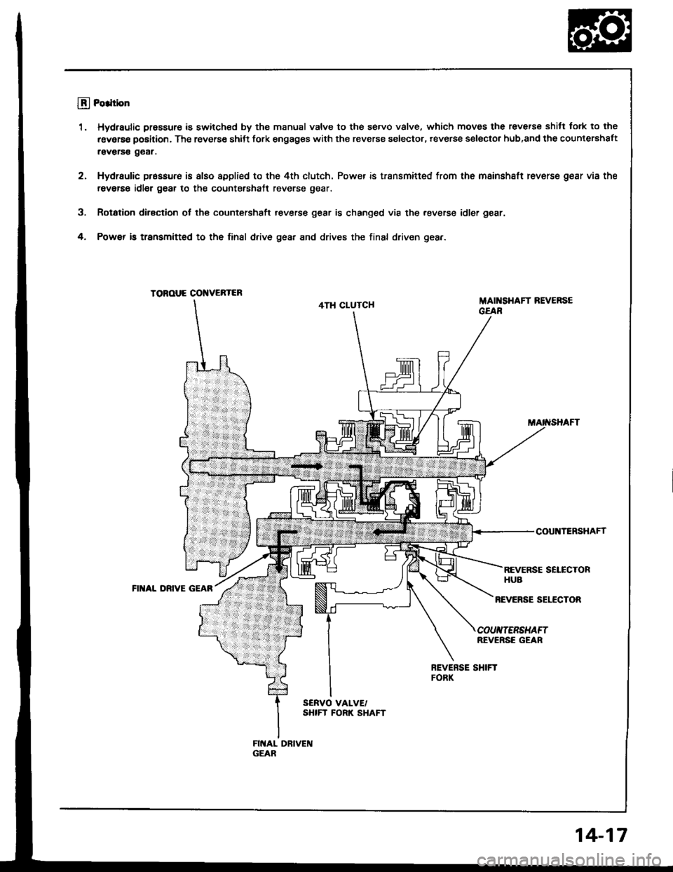
llj Po.ltbn
1. Hydraulic pressure is swilched by the manual valve to the se.vo v8lve, which moves the reverse shilt tork to the
r€verse position. The reverse shiJt fork engages with the reverse selector, reverse selsctor hub,and the countershaft
raverss g€ar.
2. Hydraulic pr6ssure is also appli€d to the 4th clutch. Power is transmifted from the mainshaft reverse gear via the
revetse idler g6ar to the countershaft reverse gear.
3. Rotation dirsction ol the countershsft reverse gear is changed via the .everse idler gear.
4. Powef b transmitted to the linal drive gear and drives the final driven gear.
TOROUE CONVEBTER
4TH CLUTCHMAI SHAFT REVERSEGEAR
COUNTERSHAFf
REVERSE SELECTORHUBFII{AL DRIVE GEAR
REVEFSE SELECTOR
COUIITERSHAFTREVERSE GEAR
14-17
Page 410 of 1413
Description
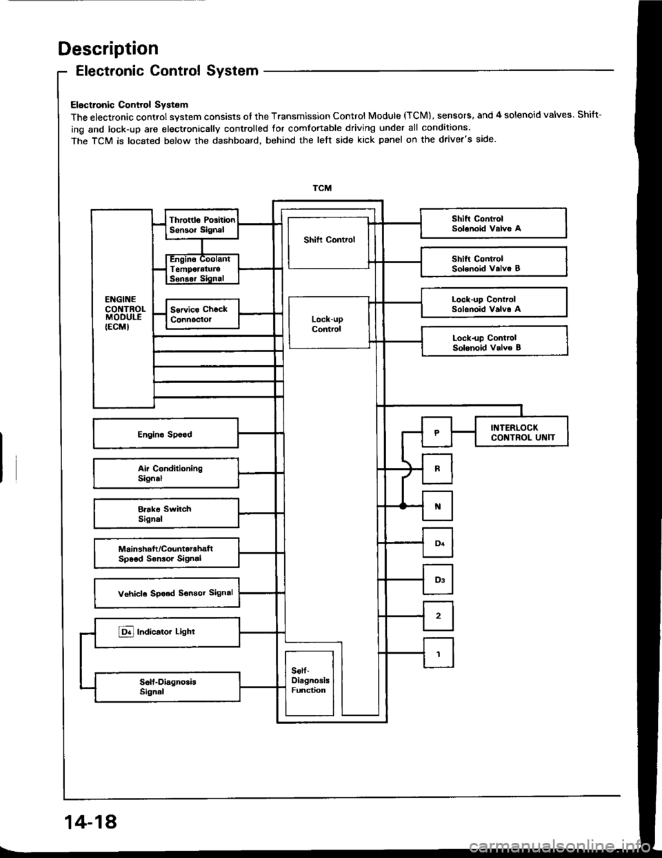
Electronic Control System
Electronic Control System
The electronic control system consists of the Transmission Control Module (TCM), sensors. and 4 solenoid valves. Shift-
ing and lock-up are elect.onically controlled for comfortable driving under all conditions.
The TCM is located below the dashboard, behind the left side kick panel on the driver's side.
Lock-up ControlSolonoid Valvo A
14-18
Trending: air suspension, Clutch replace, fuse box, spark plugs, light, radiator cap, center console
