Valve ACURA INTEGRA 1994 Service Repair Manual
[x] Cancel search | Manufacturer: ACURA, Model Year: 1994, Model line: INTEGRA, Model: ACURA INTEGRA 1994Pages: 1413, PDF Size: 37.94 MB
Page 19 of 1413

Standards and Service Limits
Cylinder Head/Valve Train (B188t enginelSecti6
*: Measured between the camshaft and rocker arm.
NH: NIHON HATSUJO manufactur€d valve spring
CH: CHUO HATSUJO manufacturod valve sDrino
- Declron
MEASUREMENTSTANDARD {NEWI '
SERVICE LIMIT
Compression250 rpm and wide open th.ottl€ Nominal
kPa (kgflcm?, psi) Minimum
Maximum variation
1,370 (14.0, 199)
930 (9.5, 140)
200 t2.0,2a)
Cylinder h.adW6rpage
Heightr31.95- 132.05 (5.195 - 5.199)
0.05 (0.002)
CamshaftEnd play
Camshaft-to-holder oil clearance
Total runout
Cam lobe height tN
EX
0.05 - 0.15 (0.002 - 0.0061
0.030 - 0.069 10.0012 - 0.0027)
0.03 (0.001) max.
33.7 16 11 .327 1l
33.528 (1.3200)
0.5 (0.02)
0.1s {0.006)
0.04 (0.002)
Valve clearance (Cold)* lN
EX
Valve stem O.D. tN
EX
Stem-to-guide clearance lN
EX
0.08 - 0.12 {0.003 - 0.005)
0.'r 6 - 0.20 (0.006 - 0.008)
6.580 - 6.590 (0.2591 - 0.2594)
6.550 - 6.s60 (0.2579 - 0.2583)
0.02 - 0.0s (0.001 - 0.002)
0.05 - 0.08 (0.002 - 0.003)
6.s5 (0.258)
6.52 (0.257)
0.0810.003)
0.11 (0.004)
width tN
EX
Stem instslled height tN
EX
r.25 - 1.55 (0.049 - 0.061)
1.25 - 1.55 {0.049 - 0.061)
40.765 - 41.235 (1.6049 - 1.6234)
12.763 - 43.235 t1,6a37 - 1.7022)
2.0 t0.08)
2.0 (0.08)
41.485 (1.6333)
43.485 (1.7120)
Valve springFree length {Reference} lN
EX NH
CH
42.36 (1.668)
47.09 {1.854}
47.08 (1.854)
41.s6 {1.636)
46.27 tl.A22l
46.21 l1.a22l
Valv6 guideLu. lN
EX
Installed height lN
6.61 - 6.63 (0.260 - 0.261)
6.61 - 6.6s (0.260- 0.261)
13.75 - 14.25 {0.541 - 0.561}
r5.75 - 16.25 10.620 - 0.640)
6.65 (0.262)
6.6510.2621
3-2
Page 21 of 1413

Standards and Service Limits
Cylander Head/Valve Train (B18Cl enginelSection 6
': M€asured betwoon the camshatt and rcc(er srm.
NH: NIHON HATSUJO manufacture v6lve spring
CH: CHUO HATSUJO manufscturo v6lve spring
MEASUBEMENTSTA]TDARD INEWISERV|C€ UM|T
Compr€6sion250 rpm and wide op€n throttle Nomin6l
kPa lkgl/cmr, psi) Minimum
Maximum variation
1,860 (19.0, 270)
930 (9.s, 140)
200 t2.o,2a)
Cylind6r hoadWarpage
H6ight'r41.95 - 1C2.05 (5.s89 - 5.593)
0.05 {0.002)
C.mshsftEnd play
Camshaft-to-holdsr oil clearance
Total runout
Cam lobo height lN Primery
Mid
Socondary
EX Primary
Mid
Secondary
0.05 - 0.1s (0.002 - 0.006)
0.050 - 0.089 (0.0020 - 0.0035)
0.015 (0.0006) max.
33.411{1.3154)
36.377 tl.13221
34.547 (1.3601)
33.1110.3036)
35.72011.4063)
34.381 {1.3536)
0.5 (0.02)
0.15 {0.006)
0.03 (0.001)
Valvo clorrance lcoldl* lN
EX
Valve stem O.D. lN
EX
Stom-to-guid6 clerrsnco lN
EX
0.15 - 0.19 {0.006 - 0.007}
0.17 - 0.21 (0.007 - 0.008)
5.475 - 5.48s (0.2156 - 0.21591
5.450 - 5.460 (0.2146 - 0.21s0'
0.025 - 0.055 {0.00'10 - 0.0022}
0.050 - 0.080 (0.0020 - 0.0031)
5.11510.21441
s.420 {0.2134)
0.08 10.003)
0.11{0.(x)4)
Valvo seatWidth tN
EX
Sr6m installed h€ight lN
EX
1.25 - 't.5s (0.049 - 0.06't)'1.25 - 1.s5 {0.049 - 0.061)
37.465 - 37.935 ('1.4750 - 1.4935)
37.16s - 37.635 t1.4632 - 1.4817)
2.0 (0.08)
2.0 (0.08)
38.185 (1.5033)
37.885 (1.491s)
Valv€ BpringFre6length (Roferenca) lN Outer
Inner NH
CH
EX NH
CH
41.05 (r.6161
36.'16 {1.4241
36.19 t1.425)
41.96 (1.652)
41.94 {1.651)
40.26 (1.585)
35.30 (1.390)
35.30 (1.390)
40.95 (1.612)
40.95 (1.612)
Valve guidol.D. tN
EX
Instslled hoight lN
EX
5.51 - 5.53 (0.217 - 0.218)
5.5r - 5.53 {0.2r7 - 0.218)
12.55 - r3.0s (0.494 - 0.514)
12.55 - 13.05 (0.494 - 0.s14t
5.55 (0.219)
5.5s {0.219}
Rock€r ermArm-to-shaft clearance lN
EX
0.025 - 0.0s2 {0.0010 - 0.0020)
0.025 - 0.0s2 (0.0010 - 0.0020)
0.08 (0.003)
0.08 (0.003)
3-4
Page 23 of 1413
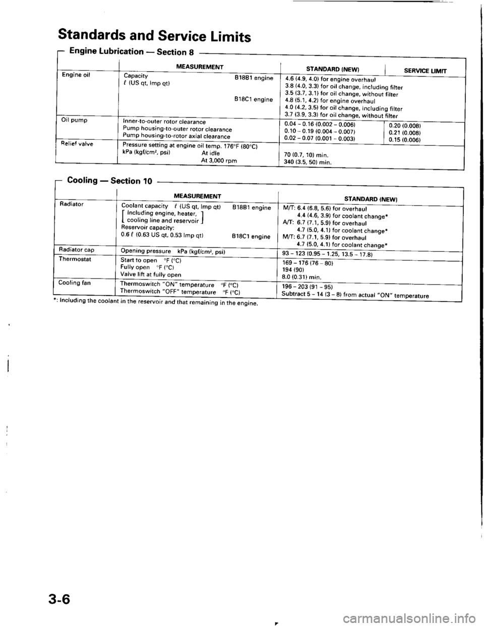
Standards and Service Limits
Engine Lubrication - Section g
Cooling - Section t0
ng the coolant in the reservoir and that remaining in the engine.
eclton u _
MEASUREMENTSTANDARD INEW}SERVICE LIMTT
g talter
tiher
g filter
Engine oilCapacity etaet engine
f (US qt, lmp qt)
818C1 engine
Inner-to-outer rotor clearance
Pump horising-to-outer rotor clearance
Pump housing-to,rotor axial clearance
rressure setting at engine oil temp. 176.F {gO.Ct
kPa lkgtcm,, psi) At idte
At 3,000 rpm
4.6 {4.9, 4.0}tor engine overhaul
3.8 (4.0, 3.3) for oil change, inctudin
3.513.7, 3.11 for oil change, without
4.8 {5.1, 4.2) for engine overhaul
4.0 (4.2, 3.5) lor oit change, includin
3.7 i3.9 3 3l fdr ^il .hi
Oil pump
0.04 - 0.16 (0.002 - 0.006)
0.10 - 0.19 (0.004 _ 0.007)
0.02 - 0.07 (0.001 , 0.003)
0.20 (0.008)
0.21 (0.008)
0.1s (0.006)
Relief valve
70 (0.7, 10) min.
3{0 {3.5,50) min.
MEASUBEMENTSTANDARD INEWI
RadialorCoolant capacity I {US qt, lmp
I Including engine, heater, I
I cooling line and reservoir I
Reservoir capacity:
0.61 (0.63 US qt,0.53 tmp qt)
q0 81881 engine
818C1 engine
Opening pressure kPa (kgf/cm?, psi)
start to open oF (.C)
Fully open .F (.C)
Valve lift at fully open
lhermoswitch "ON" temperature .F {oC)
Thermoswitch "OFF" temporature "F (.C)
M/T: 6.4 (6.8, 5.6)tor overhaul
4.4 (4.6.3.9) f6r s66lsn1gh66q.*
A,rf: 6.7 {7.1, 5.9) for overhaul
4.7 {5.0, 4.1) for coolant chanoe*
M/T: 6.7 {7.1, 5.9} for overhaul
4.7 {5.0, 4.1) for coolant chanoe*
,3 - 113 toss - trs, r3= Jt&
-
196 - 203 (91 - 95)
Subtract 5 - 14 (3 - 8) from actuat -ON',
169 - 176
194 (90,
8.0 (0.31)
{76 80}
temperature
Radiator cap
Thermostst
Cooling fan
3-6
Page 30 of 1413
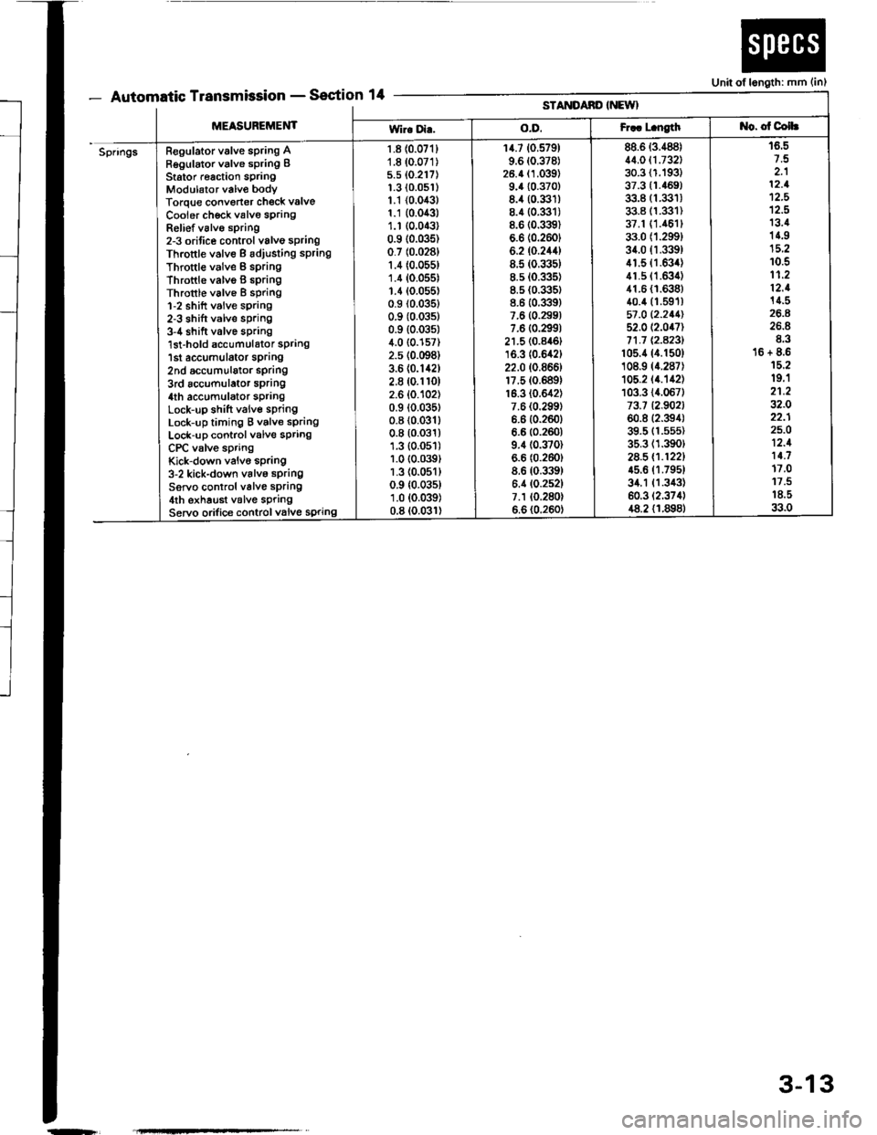
- Automatic TransmissionSection 14Unit of length: mm (in)
[t!'tttltttt tt -
MEASUREMENT
STANDAND INEWI
Wir. Di..o.D.Fr.. L.ngtht{o. of Colh
SpringsRegulator valve spring ARegulator valve spring IStator r€action springModulator valv€ bodyTorque convorter check valve
Cooier ch€ck valve sprangRelief v6lvo spring2-3 orifice control valvo springThrottle valve B adiusting sPring
Throttle valve B springThrottle valvo B 6pringThrottle valve I spring1-2 shift valve sprang2-3 shift valve spring3-4 shift valve spring'lst-hold accumulator spring1st accumulator sprang2nd accumulalor spdng3rd accumulator spring4th accumulator sPrangLock-up shift valve springLock-up timing B valve springLock-up control valve springCPC valve springKick-down valvo spring3-2 kick-down valvo springServo control valve spring4th exhaust v6lve springServo orifice controlvalve spring
1.8 {0.071}1.8 (0.071)
5.5 (0.217)
1.3 {0.0s1)1.1 {0.043}1.1 {0.043)1.r (0.043)
0.9 (0.035)
0.7 (0.0281
1.4 (0.055)
1.4 (0.055)
1.1(0.055)0.9 (0.0351
0.9 (0.0351
0.9 {0.035)4.0 {0.157)2.5 (0.098)
3.6 (0.142)
2.8 (0.1r0)
2.6 (0.102)
0.9 (0.035t
0.8 (0.0311
0.8 (0.031)
1.3 (0.051)
1.0 (0.039t
1.3 (0.051)
0.9 {0.035)1.0 (0.039)
0.8 (0.031)
14.7 (0.579)
9.6 (0.378)
26.4 (1.039)
9.4 {0.370}8.4 (0.331)
8.4 (0.3:]t)
8.6 (0.3l9)
6.6 (0.2601
6.2 (0.244)
8.5 (0.335)
8.5 (0.335)
8.5 (0.335)
8.6 (0.339)
7.6 (0.299)
7.6 (0.2991
21.5 (0.846t
16.3 (0.642)
22.0 (0.866)
17.5 (0.689)
16.3 (0.642)
7.6 {0.299)6.6 {0.260}6.6 (0.260)
9.4 (0.370)
6.6 (0.260)
8.6 (0.339)
6.4 (0.252)
7.1 (0.280)
6.6 (0.260)
88.6 (3.488)
11.011.732130.3 (1.193)
37.3 {1.469)33.8 (1.331)
33.8 (1.331)
37.1 (1.461t
33.0 (1.299)
34.0 fi.339)41.5 (1.634)
41.5 (1.63i1)
41.6 {1.638}40.4 (1.591)
57 ,0 12.211152.0 (2.047)
71.1 Q.A23l't05.4 (4.150)
108.9 (4.287)
105.2 (4.'�142)
103.3 {4.067)73.7 12.902160.8 (2.394)
39.5 (1.5s5)
35.3 (1.390)
2a.5 (.1221
45.6 (1.795t
34.1 {1.343)60.3 (2.374)
48.2 {1.898}
16.5
2.112.1't2,5
12.513.414.9
10.511.212.114.5
26.8E.316 + 8.615.219.'l21.232.022.125.O12.111.717.011.518.533.0
-r
3-13
Page 31 of 1413
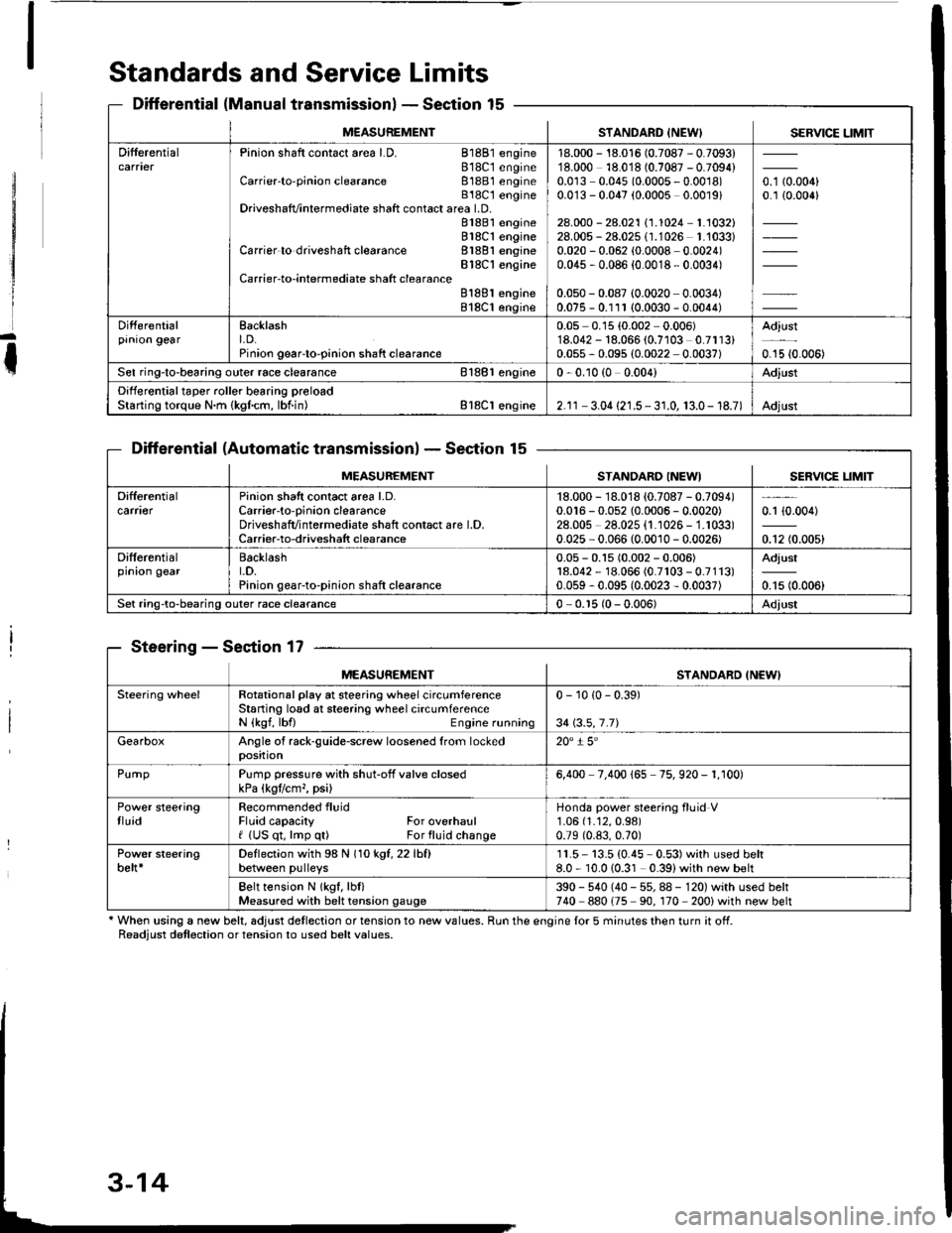
Standards and Service Limits
Differential (Manual transmissionlSection 15
Differential (Automatic transmissionlSection 15
Steering - Section 17
' When using a new belt, adjust detlection or tension to new values. Run the engine lor 5 minutes then turn it off.Readiust detlection or tension to used belt values.
M€ASUREMENTSTANDARD INEW) SERVICE LIMIT
DifferentialPinion shaft contact area LD. 81881 engine818C1 engineCarrier'to-pinion clearance 81881 engineB18C t engineDriveshafvintermediate shaft contact area LD.81881 engine818C1 engineCarrier to driveshaft clearance 81881 engineBlSC'l engineCarrier-to-intermediate shatt clearanceB188l engine818C1 engine
18.000 - 18.016 (0.7087 - 0.7093)18.000 18.018 (0.7087 - 0.7094)0.0r3 0.045 (0.0005 - 0.0018)0.0'13 - 0.047 (0.0005 0.0019)
28.000 - 28.021 \1.1024-1.1032128.005 - 28.025 (1.1026 1.'1033)0.020 - 0.062 (0.0008 0.0024)0.045 , 0.086 {0.0018 - 0.0034)
0.050 - 0.087 (0.0020 0.0034)0.075 - 0.111 (0.0030 - 0.0044)
o. t aron,0.1 {0.006}
Differentialprnron gearEacklasht. D.Pinion geaFto-pinion shaft clearance
0.05 0.15 (0.002 0.006)'18.042 - 18.066 (0.7103 0.7113)0.055 - 0.095 (0.0022 0.0037)
Adjust
0.15 {0.006)
Sel ring-to-bearing outer race clearance 81881 engin€0 - 0.10 (0 0.004)Adjust
Differential taper roller bearing preloadStarting torque N.m {kgfcm, lbf.in) Bl8Cl engine2.1r - 3.04 {21.5 - 3 r.0, 13.0- 18.7)Adjust
MEASUREMENTSTANDARO INEWISERVICE LIM]T
Difterentialcarfl€rPinion shatt contact area l.D.Carrier-to-oinion clearanceDriveshafvintermediate shaft contact are l.D.Carrier-to-driveshatt clearance
18.000 - 18.018 {0.7087 - 0.7094)0.016 - 0.052 {0.0006 - 0.0020)28.00s 28.025 {1.1026 - 1.1033)0.025 - 0.066 (0.0010 - 0.0026)
0.1 {0.004)
0.12 (0.005)
Differentialprnron gearBacklasht.D.Pinion gear-to-pinion shaft clearance
0.05 - 0.15 (0.002 - 0.006)18.042 - 18.066 (0.7r03 - 0.7113)0.059 - 0.095 (0.0023 - 0.0037)
Adjust
0.15 (0.006)
Set ring-to-bearing outer race clearance0 - 0.r5 (0 - 0.006)Adjust
MEASUREMENTSTANDARD INEWI
Steering wheelRotational play at steering wheel circumferenceStaning losd at steering wheel circumferenceN {kgf, lbfl Engine running
0 - 10 {0 - 0.39)
34 \3.5,7.71
GearboxAngle of rack-guide-screw loosened from lockedposition20" i 5'
PurnpPump pressure with shut-off valve closedkPa (kgtlcm,, psi)6,400 7.400 165 75. 920 - 1. r00)
Power steeringtluidRecommended fluidFluid capacity For overhaulf (US qt, lmp q0 For fluid change
Honda power steering fluid V1.06 (1.12,0.98)
0.79 (0.83,0.70)
Power steeringbelt*Deflection with 98 N (1okgt,22lhfl
between pulleys11.5- 13.5 (0.45 0.53)with used belt8.0 - 10.010.31 0.39)with new belt
Belt tension N lkgf, lbl)Measured with belt tension gauge390 - 540 (40 - 55, 88 - 120) with used belt740 880175 90. 170 200) with new belt
Page 34 of 1413
![ACURA INTEGRA 1994 Service Repair Manual Design Specifications
]TEMMETRICENGLISHNOIES
: vENSTONSOveralllength 3 DOOR
4 DOOR
Ov€rallWidth
Overall Height 3 DOOR
4 DOOR
Wheelbase 3 DOOR
4 DOOR
Track F/R
Ground Clearance
Seating Capacity
4.38 ACURA INTEGRA 1994 Service Repair Manual Design Specifications
]TEMMETRICENGLISHNOIES
: vENSTONSOveralllength 3 DOOR
4 DOOR
Ov€rallWidth
Overall Height 3 DOOR
4 DOOR
Wheelbase 3 DOOR
4 DOOR
Track F/R
Ground Clearance
Seating Capacity
4.38](/img/32/56982/w960_56982-33.png)
Design Specifications
]TEMMETRICENGLISHNOIES
:' vENSTONSOveralllength 3 DOOR
4 DOOR
Ov€rallWidth
Overall Height 3 DOOR
4 DOOR
Wheelbase 3 DOOR
4 DOOR
Track F/R
Ground Clearance
Seating Capacity
4.380 mm
4.525 mm
'1,710 mm
1,335 mm
1,370 mm
2,570 mm
2,620 mm
't,475/1,470 mm
150 mm
Four (3 DOOR)
172.1in
178.1 in
67.3 in
52.6 in
101.2 in
103.1 in
5|8.1/57.9 in
Five (4 DOOR)
,rerght (usA)cross V€hicle Weight Rating {GVWR)3,680lbs
'le,ght {CANADA)Gross Vehicls Weight Rating {GVWR)1,670 kg
:\GINEType81881 engine
818C1 engine
Cylinder Arrangement
Bore and Stroke
Displacement
Compression Ratio
81881
818C1
81881
B18C I
81881
B 18C1
81881
818C1
engrne
engane
engrne
engine
engine
engine
engine
engine
L!brication Systom
OilPump Displacement
Wster Pump Displacement
FuelRequired
81881
B18C 1
81881
B 18C1
91881
engrne
engrne
engine
engine
engine
818C1 engine
Water-cooled, 4-stroke DOHC
gasoline engine
Watercooled, 4-stroke DOHC
VTEC gasoline engine
Inline 4-cylinder, transverse
81.0 x 89.0 mm
81.0 x 87.2 mm
1,834 cm3 (mf )
1,797 cm3 (m{)
3.19 x 3.50 in
3.19 x 3.43 in
112 cu-in
110 cu-in
9.2:1
10.0 : 1
Eelt driven, OOHC 4 valve per cylinder
Belt driven, DOHC VTEC
4 valve per cylinder
Forced and wet sump, trochoid pump
50, {53 US qt, 44 lmp qt)/minute'l
71 f {75 US qt, 62 lmp qt)/minute"
140 f (148 US qt, 123 lmp qt)/minute*!
140 f (148 US qt. 123 lmp qt)/minute*'
UNLEADED gasoline with 86 Pump
Octane Numb€r or higher
Premium UNLEADED gasoline wilh
91 Pump Octane Number or higher
STARTERTypo
NormalOutput
NominalVoltage
Hour Rating
Direction of Rotation
Weight
Gear reduction
1.4 kW
12V
30 seconds
Clockwise as viewed lrom g6ar end
3.7 k9 | 8.3lbs
CLUTCHClutch Type
Clutch Facing Area
M/TSingle plate dry, diaphragm spring
Torq!e converter
203 cm'� I 31 sq-in
TRANSMISSIONTransmission Type M/T
Primary Reduction
Synchronized 5-speed forward, 1 reverse
Electronically controlled
4-speed automatic. 1 rcverse
Diract 1 : 1
'1: At 6,000 engine
'2: At 7,600 engine
rpm
rpm
(cont'd)
3-17
Page 45 of 1413
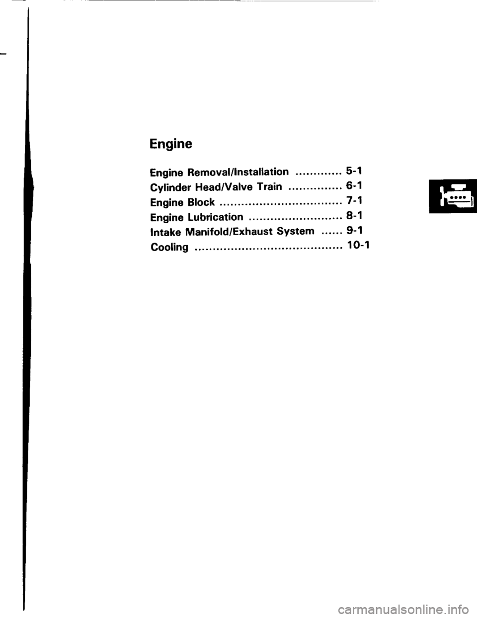
Engine
Engine Removal/lnstallation ...''........ 5-1
Cylinder Head/Valve Train ..'............ 6-1
Engine Block ..........7-1
Engine Lubrication ......... 8-1
Intake Manifold/Exhaust System ...... 9-1
Cooling ....... 1O-1
Page 60 of 1413
![ACURA INTEGRA 1994 Service Repair Manual Insrall the left front mount, then tighten the bolts in
the numbered sequence as shown (O-@),
O 12 x 1.25 ]n]n83 N.m 18.5 kst.m,61 lbt.ftlReplace.
@ 12 r 1.25 mm59 N.m {6.0 kgl.n,43 tb{.ftlReplace.
@ ACURA INTEGRA 1994 Service Repair Manual Insrall the left front mount, then tighten the bolts in
the numbered sequence as shown (O-@),
O 12 x 1.25 ]n]n83 N.m 18.5 kst.m,61 lbt.ftlReplace.
@ 12 r 1.25 mm59 N.m {6.0 kgl.n,43 tb{.ftlReplace.
@](/img/32/56982/w960_56982-59.png)
Insrall the left front mount, then tighten the bolts in
the numbered sequence as shown (O-@),
O 12 x 1.25 ]n]n83 N.m 18.5 kst.m,61 lbt.ftlReplace.
@ 12 r 1.25 mm59 N.m {6.0 kgl.n,43 tb{.ftlReplace.
@ 10 r 1.25 mm44 N.m (4.5 kgf.m, 33 lbt.ftl
k-
5-15
a Check that the sp.ing clip on the end of each
driveshaft clicks into place.
GAUTION: Uso oow spring clips.
a Bleed air trom the cooling system at the bleed bolt
with the heater valve open (see page 10-5).
a Adjust the th.ottle cable (see section 1 1).
a Check the clutch pedal tree play lsee section 12).
a Check that the transmission shifts into gear
smoothlv,
a Adiust the tension of the following drive belts.
Alternator belt {s€e section 23).
P/S pump belt {see section 17).
A/C comoressor belt (see section 22).
a Inspect tor fuel leakage (see section 1 1).
. After assembling fuel line parts, turn on the ig-
nition switch (do not operate th€ starter) so
that the Juel pump operates for approximat€-
lV two seconds and the tuel line pressurizes.
Repeat this operation two or three times and
check for fuel leakage at any point in the fuel
line.
(cont'd)
Page 61 of 1413
il
I
I
I
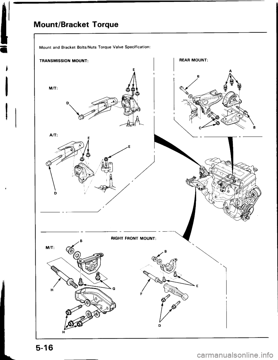
Mount/Bracket Torque
Mount and Bracket Eolts/Nuts Torque Valve Specification:
TRANSMISSION MOUNT:
Page 64 of 1413

Cylinder Head/Valve Train
81881 engine
Speciaf Tools .............6-2
Valve Clearance
Adiustment ............6-3
Valve Seals
Replacement (cylinder head
removal not required) ..................... 6-5
Reconditioning ......6-27
Timing gelt
lllustrated Index ............................... 6-7
Inspection .............. 6-9
Tension Adiustment ........................ 6-9
Removal .................6-10
Installation .............6-12
Crankshaft Pulley Bolt
Replacement .........6-8