relay ACURA INTEGRA 1998 Service Repair Manual
[x] Cancel search | Manufacturer: ACURA, Model Year: 1998, Model line: INTEGRA, Model: ACURA INTEGRA 1998Pages: 1680, PDF Size: 53.14 MB
Page 1179 of 1680
UNDER.DASHFUSE/RELAY 8OX
No.l5 (7.54)
No 2s (7 5A)
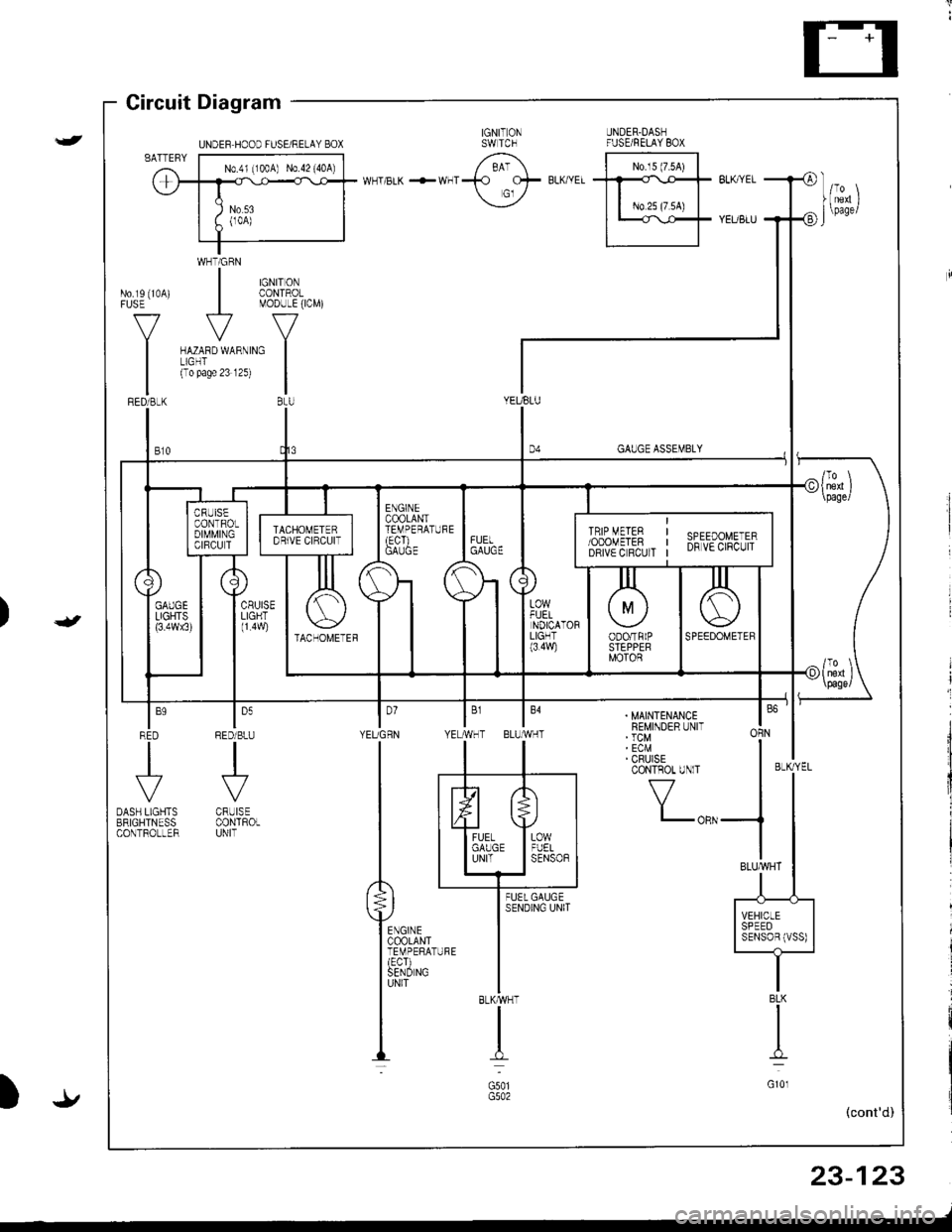
Gircuit Diagram
WHTiGRN
| $il,�4,
V
MODULE(ICM)
ru{no unrno I(To pase 23 12s)
|BtU
No.rs (10A)FUSE
V
I
GAUGE ASSEMBLY
YEUBLU
t,,
| ,,J,,
1l
|;;il'-II SPEED II SENSoBIVSS) |-t-
. MAINTENANCEREMINDER UNIT' TCM' ECM' CRUISECONTROT UNlT
f7
I-oRN
BLKMHT
I
G501
I'YEUGRN YE
ln
tl
P**,,,'
ffirxl-"
louRED/BLU
.J'-
CRUISECONTROLUNIT
BLK
I
G10l
23-123
-/
UNDEF HOOD FUSE/RELAY BOX
Page 1184 of 1680
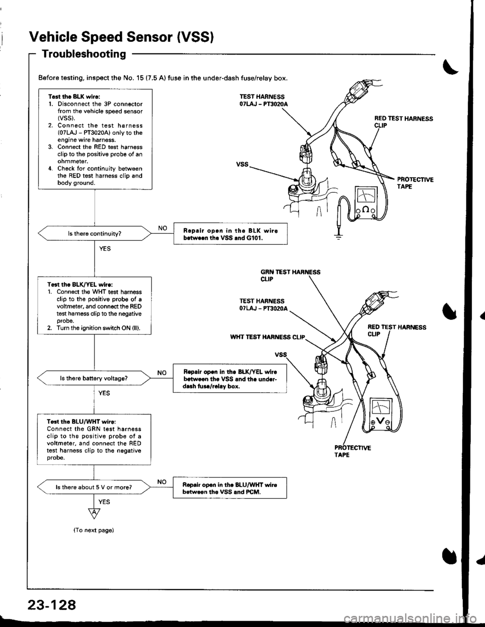
Vehicle Speed Sensor (VSSI
Troubleshooting
{To next page)
REO TEST HARNESS
PBOTECTIVETAPE
Test tho 8LK wiro:1. Disconnect the 3P connectorfrom the vohicle speed sensor(vss).
2. Connect the test harness(07LA,J - PT3020A) only to theengine wire harnoss.3, Connect the RED test harnessclip to the positive probe of anohmmel€r.4. Check for continuity betwoenthe RED test harness clip andbody ground.
Roplir op.n in th. BLK wirob.tw..n tha VSS .nd G101.
To3t thc BLK/YEL wiro:1. Conn6ct th€ WHT test harnessclip to the positive prob€ of avoltmeter, and connect the REDt€st harness clip to the nogativeprobe.2. Turn the ignition switch ON (lll.
R.p.lr op.n In tho BLK/YEL wirebrtw..n th. VSS and th. under-dr.h tu../r.l!y box.
Tort th. BLU/WHT wiro:Connect the GRN test harnessclip to the positive prob€ ot avoltmeter, and connect the REDtest harness clip to the nggatjveprobe.
Roprh op.n in th. 8LU/WHT wireb.tw.on tho VSS lnd PCM.ls there about 5 V or more?
Before testing, inspect the No. 15 (7,5 A) fuse in the under-dash fuse/relay box.
GRN TESTCLIP
TEST HARNESSOTLAJ - PT3O2OA
w'{T TES? HARIVESS CLIP
TAPE
23-128
Page 1187 of 1680
)
{
t.t
t.!
23-131
Fuel Gauge
Gauge Test
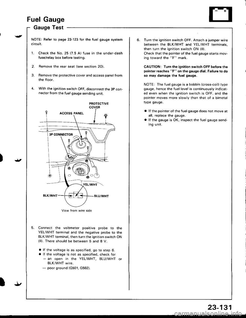
NOTE: Refer to page 23-123 for the fuel gauge system
circuit.
1. Check the No. 25 (7.5 A) fuse in the under-dash
fuse/relay box before testing.
2. Remove the rear seat (see section 20).
Remove the protective cover and access panel from
the tloor.
With the ignition switch OFF, disconnect the 3p con-nector from the fuel gauge sending unit.
3.
4.
5.
PROTECTIVECOVER
Connect the voltmeter positive probe to the
YEL/WHT terminal and the negative probe to the
BLK/WHT terminal, then turn the ignition switch ON(ll). The.e should be between 5 and 8 V.
a lf the voltage is as specified, go to step 6.a lI the voltage is not as specified, check for- an open in the YEL/WHT, BLU/WHT or
BLK/WHT wire.- poor ground (G501, G502).
3P CONNECTOR
View from wire side
6.Turn the ignition switch OFF. Attach a jumper wire
between the BLKMHT and YEL/WHT terminals,
then turn the ignition switch ON {1.,.
Check that the pointer of the fuel gauge starls mov-
ing toward the "F" mark.
CAUTION: Turn the ignition switch OFF before the
pointer reaches "F" on the gauge dial, Failure to do
so may damage the tuel gauge.
NOTE: The fuel gauge is a bobbin (cross-coil) type
gauge, hence the fuel level is continuously indicat-
ed even when the ignition switch is OFF, and thepointer moves more slowlv than that ol a bimetal
rype gauge.
a lf the pointer ol the fuel gauge does not move at
all, replace the gauge.
a It the gauge is OK, inspect the fuel gauge send-
ing unit.
Page 1190 of 1680
Engine Coolant Temperature (ECT) Gauge
Gauge Test
NOTE: Refer to page 23-123 for the wiring description of
the engine coolant temperature (ECT) gauge circuit dia-
gram.
1. Check the No. 25 (7.5 A) fuse in the under-dash
fuse/relay box before testing.
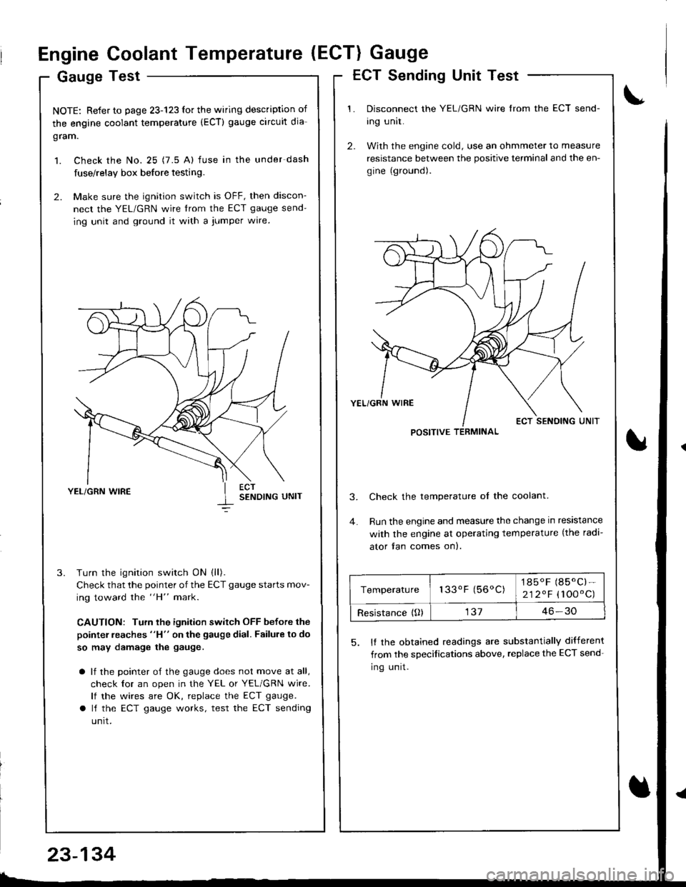
2. Make sure the ignition switch is OFF, then discon-
nect the YEL/GRN wire trom the ECT gauge send-
ing unit and ground it with a jumper wire.
YEL/GRN WIRESENDING UNIT
Turn the ignition switch ON (ll).
Check that the pointer of the ECT gauge starts mov-
ing toward the "H" mark.
CAUTION: Turn the ignition switch OFF before the
pointer reaches "H" on the gauge dial. Failure to do
so may damage the gauge.
a lf the pointer of the gauge does not move at all,
check lor an open in the YEL or YEL/GRN wire.
lf the wires are OK, replace the ECT gauge.
a lf the ECT gauge works, test the ECT sending
unrt.
ECT Sending Unit Test
Disconnect the YEL/GRN wire from the ECT send-
ing unit.
With the engine cold, use an ohmmeter to measure
resistance between the positive terminal and the en-
gine (ground).
Check the temperature ol the coolant.
Run the engine and measure the change in resistance
with the engine at operating temperature (the radi-
ator fan comes on).
5. It the obtained readings are substantially different
from the sDecifications above, replace the ECT send-
Ing unrt.
POSITIVE TERMINAL
Temperature133oF (56oC)1850F (85.C)-
212.F (100'C)
Resistance {O)13746-30
23-134
Page 1194 of 1680

Maintenance Reminder System
Circuit Diagram
UNOER.HOOO FUSEIRELAY BOX
N0.41 (lmA) No 42 (40A)
MAINTENANCE REMINDER UNIT
8LK
c201G401
23-138
Page 1195 of 1680
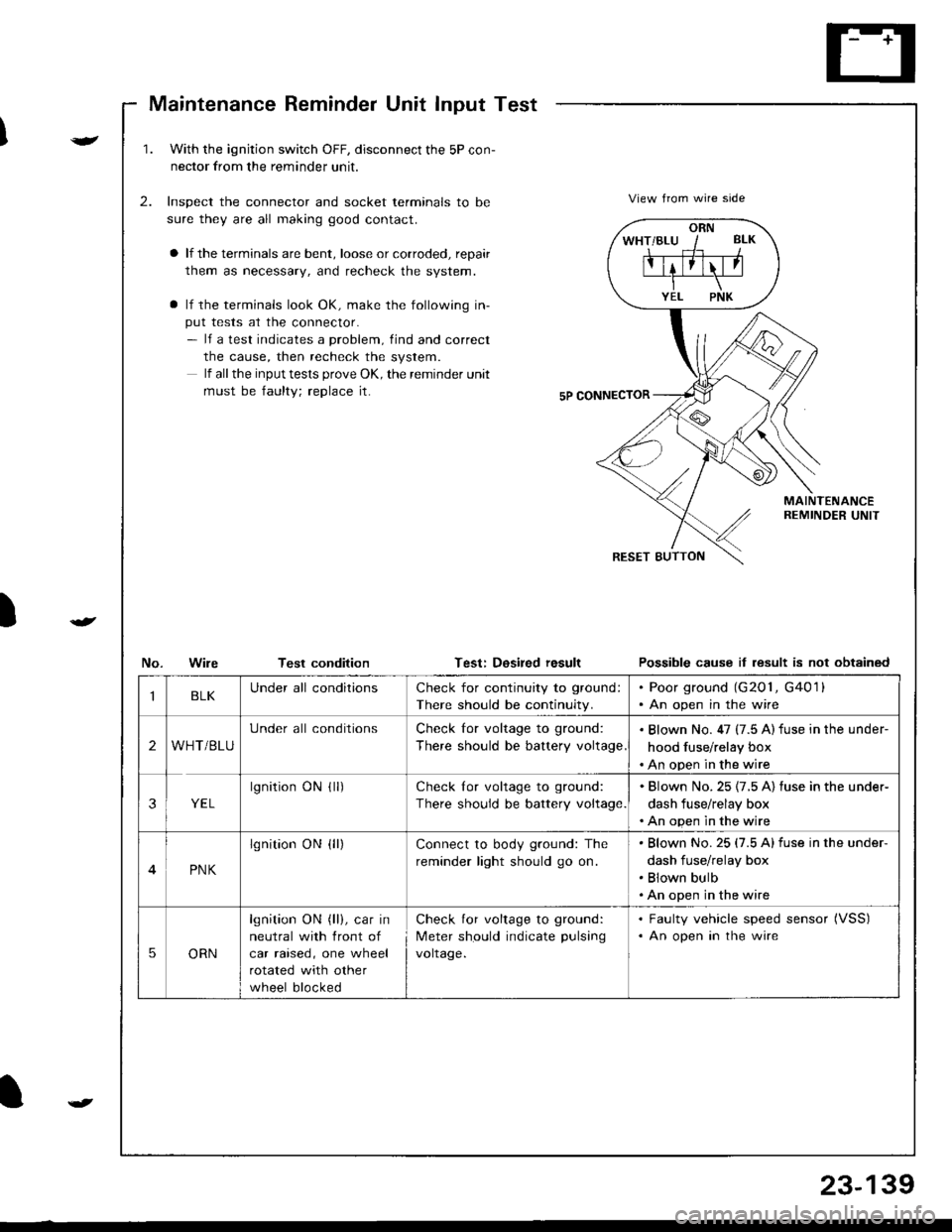
Maintenance Reminder Unit Input Test
)
v
t
1.With the ignjtion switch OFF, disconnect the 5P con-
nector from the reminder unit.
Inspect the connector and socket terminals to be
sure they are all making good contact.
a lf the terminals are bent, loose or corroded, repair
them as necessary, and recheck the system.
a lf the terminals look OK, make the following in-
put tests at the connector.- lf a test indicates a problem, find and correct
the cause, then recheck the system.
lf all the input tests prove OK, the remind€r unit
must be faulty; replace it.
2.View from wire side
MAINTENANCEREMINDER UNIT
No.WileTest conditionTest: Dosired resultPossible cause it lesult is not obtained
ORN
IBLKUnder all conditionsCheck for continuity to ground:
There should be continuity.
. Poor ground (G201, G4011. An open in the wire
2WHT/BLU
Under all conditionsCheck for voltage to ground:
There should be battery voltage
. Blown No. 47 (7.5 A) fuse in the under-
hood fuse/relay box. An open in the wire
3YEL
lgnitionONflr)Check lor voltage to ground:
There should be battery voltage.
. Blown No.25 {7.5 A) fuse in the under-
dash fuse/relay box. An open in the wire
4PNK
lgnition ON {ll)Connect to body ground: The
reminder light should go on.
Blown No.25 (7.5 Alfuse in the under-
dash fuse/relay box
Blown bulb
An open in the wire
5ORN
lgnition ON (ll), car in
neutral with front of
car raised, one wheel
rotated with other
wheel blocked
Check for voltage to ground:
Meter should indicate pulsang
voltage.
. Faulty vehicle speed sensor (VSS)
. An open in the wire
t
23-139
Page 1197 of 1680
![ACURA INTEGRA 1998 Service Repair Manual Circuit Diagram
)
{
{
I
UNDER-HOOD FUSEiRELAY 80XIGN TIONSWITCHUNDER-DASHFUSE/RELAY BOX
. TRANSMISS]ONCONTROLMODULE (TCM)
/;; l-^--;;;;lw--BLh ---wrl f ,:+ BLK/E- t.d\o-ft\---l
I t,;:*
IVECM
f7
ILT ACURA INTEGRA 1998 Service Repair Manual Circuit Diagram
)
{
{
I
UNDER-HOOD FUSEiRELAY 80XIGN TIONSWITCHUNDER-DASHFUSE/RELAY BOX
. TRANSMISS]ONCONTROLMODULE (TCM)
/;; l-^--;;;;lw--BLh ---wrl f ,:+ BLK/E- t.d\o-ft\---l
I t,;:*
IVECM
f7
ILT](/img/32/56983/w960_56983-1196.png)
Circuit Diagram
)
{
{
I
UNDER-HOOD FUSEiRELAY 80XIGN TIONSWITCHUNDER-DASHFUSE/RELAY BOX
. TRANSMISS]ONCONTROLMODULE (TCM)
/;; l-^--;;;;lw--BLh ---wrl f ,:+ BLK/E- t.d\o-ft\---l
I t,;:'*'
IVECM
f7
ILT GRN/BLK
YEUBLU
(n lhe gauqe assembly)D4
TRANSMISSIONCONTROLMODULErrcM)
f7
IIGRN/BLK
c6c7c8 lc9NTERLOCKCONTROLUNIT (
f7
IGRNMHT
BLK
TRANSMISSION CONTROLMODULE TICM)GRNCRN]BLULTGRNMHT
GRN/YEL
No l9 (104)FUSE
f7
IRED/BLK
A?TGEARPOSITION SWTCHRED
II
I
Y?
DASH LIGHTSBFIGHTNESSCONTROLLER
BLK
oro,G40lG20lG401
A/T GEAH POSITION NDICATOR DIMMING C RCUIT
A/T GEARPOS TIONCONSOLELIGHT(1.4w)
/ ,/ t2
{,
23-141
Page 1199 of 1680
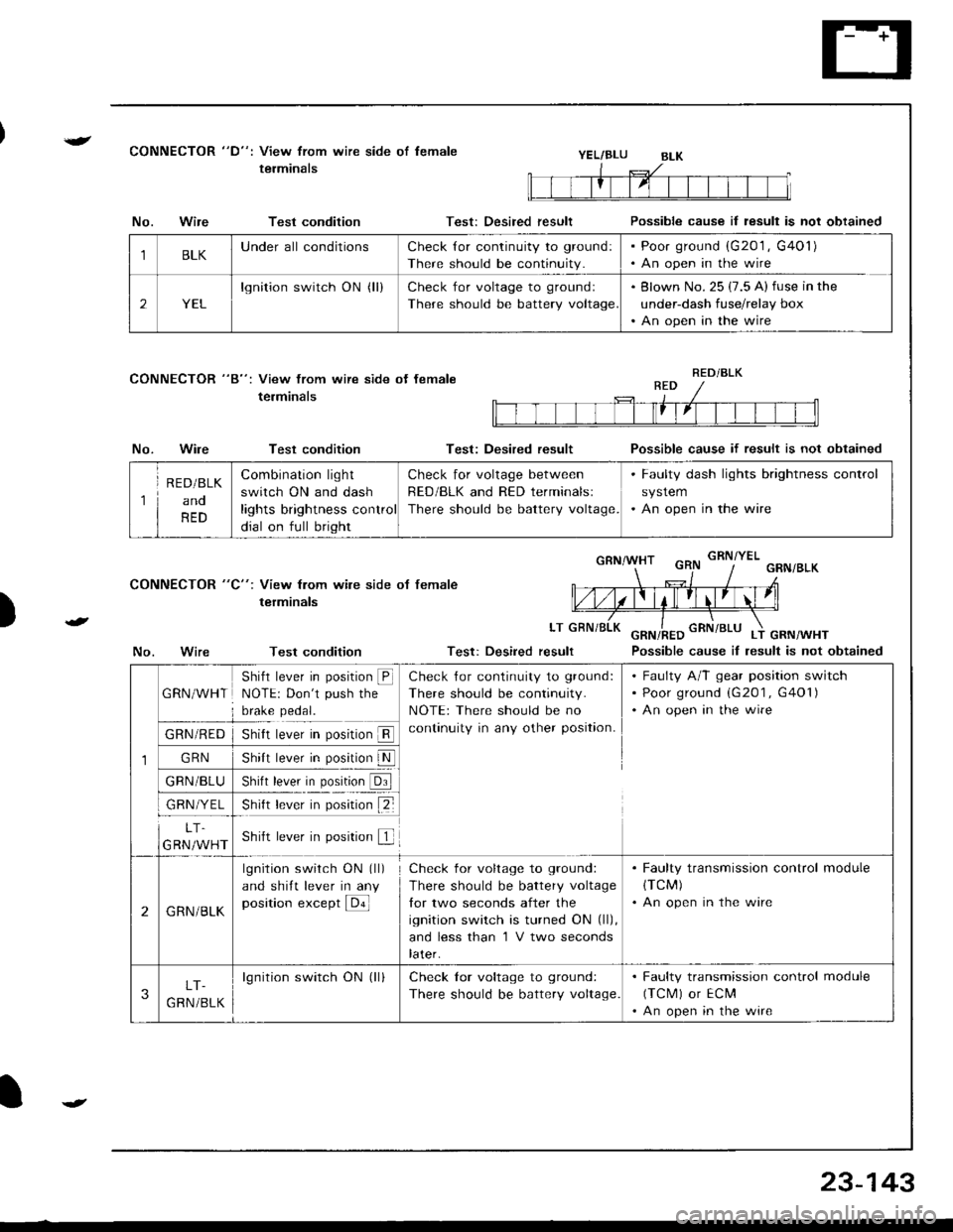
{CONNECTOR "D": View from wire side of lemale
terminalsYEL/BLU
CONNECTOR "8": View from wire side ot female
terminals
No.Wire
No.Wire
Test condition
Test condition
Test condition
Test: Desired result
Test: Desired result
Possible cause il result is not obtained
Possible cause if result is not obtained
Possible cause iI lesult is not obtained
)
CONNECTOR "C": View from wile side ot female
terminals
LT
No.Test: Desired result
1BLKUnderall conditionsCheck {or continuity to ground:
There should be continuity.
Poor ground (G201 , G401)
An open in the wire
2YEL
lgnition switch ON (ll)Check for voltage to groundl
There should be battery voltage
Blown No. 25 (7.5 A) fuse in the
under-dash fuse/relay box
An open in the wire
RED/BLK
1
R E D/BLK
ano
RED
Combination light
switch ON and dash
lights brightness control
dial on full bright
Check for voltage between
RED/BLK and RED terminalsl
There should be battery voltage.
. Faulty dash lights brightness control
system. An open in the wire
1
GRN/WHT
Shifl lever in position @NOTE: Don't push the
brake pedal.
Check {or continuity to ground:
There should be continuity.
NOTE: There should be no
continuity in any other position.
Faulty A/T gear position switch
Poor ground (G201 , G401)
An open in the wire
GRN/RED
GRN
GRN/BLU
GRN/YEL
5nrrI rever In pos[ron ll
shl, b*|' il. p"1,!lN
)nrn rever In posrron url
snt r""-. r p*;ir" tZ-
LT.
GRN/WHTShift lever in position f
2GRN/BLK
lgnition switch ON (ll)
and shift lever in any
position except E
Check for voltage to ground:
There should be battery voltage
lor two seconds after the
ignition switch is turned ON (ll),
and less than 'l V two seconds
later.
. Faulty transmission control module(TCM)
. An open in the wire
3LT-
G RN /BLK
lgnition switch ON (ll)Check lor voltage to ground:
There should be battery voltage.
. Faulty transmission control module
(TCM) or ECM'An open in the wire
23-143
Page 1204 of 1680
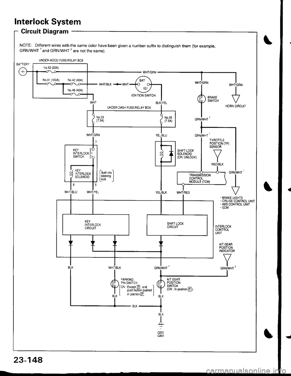
lnterlock System
Circuit Diagram
NOTE: Different wires with the same color have been given a number suflix to distinguish them (for example,cRNA/VHT I and cRNMHT '� are not the same).
WHT/ BLK .-- WHI
cnrruvgr'
+. BRAKE LIGNTS.CSUISE CONTROLUNIT. ABS COIITROL UNIT' ECM
INTEBLOCKCONTROLUNIT
A]'IGEARPOStTIONINOICATOR
v
t,
UNDER-HOOO FUSEi RELAY BOX
N0.41 (100A) N0.42 (404)
YEUBLUcnrivrr '
WHT/BLU
KEYINTERLOCKswtTcH
THBOTTLEPosrT|0N (TP)SENSOR
f7
IRED/BLK
(Cjl :in posiron E t
23-14A
Page 1205 of 1680
){r/
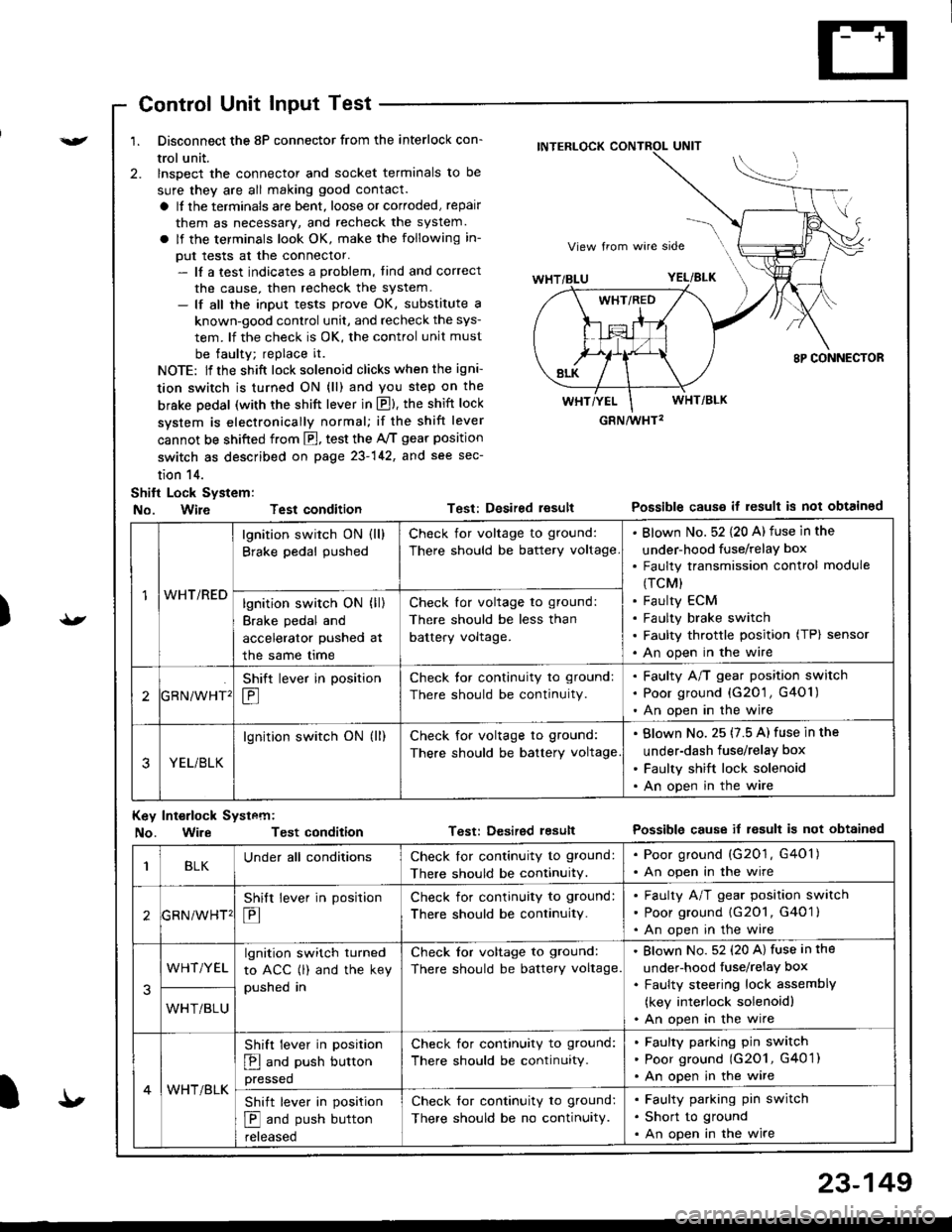
Control Unit Input Test
1. Disconnect the 8P connector from the interlock con-
trol unit.
2. lnspect the connector and socket terminals to be
sure they are all making good contact.
a It the terminals are bent, loose or corroded, repair
them as necessary, and recheck the system.
a lf the terminals look OK, make the following in-
put tests at the connector.- lf a test indicates a problem, tind and correct
the cause, then recheck the system.- lf all the input tests prove OK, substitute a
known-good control unit, and recheck the sys-
tem. lf the check is OK, the control unit must
be faulty; replace it.
NOTE: lf the shift lock solenoid clicks when the igni-
tion switch is turned ON (ll) and you step on the
brske Dedal (with the shift lever in E). the shift lock
system is electronically normal; if the shift lever
cannot be shifted from fl, test the 46 gear position
switch as described on page 23-142, and see sec-
tion 14.
Shift Lock System:
No. Wire Test condition
No. WireTest condition
Test: Desired resultPossible causs it result is not obtained
Test: Dcsired lesultPossible cause it result is not obtainsd
INTERLOCK CONTROL UNIT
GRN/wHT2
1WHT/RED
lgnition switch ON (ll)
Brake pedal pushed
Check for voltage to ground:
There should be battery voltage
Blown No. 52 {20 A) fuse in the
under-hood fuse/relaY box
Faulty transmission control module
(TCM)
Faulty ECM
Faulty brake switch
Faulty throttle position (TP) sensor
An open in the wire
lgnition switch ON (ll)
Brake pedal and
accelerator pushed at
the same me
Check for voltage to ground:
There should be less than
battery voltage.
tGRN/WHT'
Shift lever in position
E
Check tor continuity to ground:
There should be continuity.
Faulty A/T gear position switch
Poor ground {G20'1 , G401)
An open in the wire
3YEL/BLK
lgnition switch ON (ll)Check for voltage to ground:
There should be battery voltage
Blown No. 25 (7.5 A) fuse in the
under-dash fuse/relay box
Faulty shift lock solenoid
An open in the wire
Key Int€rlock Systcm:
BLKUnder all conditionsCheck lor continuity to ground:
There should be continuitY.
. Poor ground (G201, G401). An open in the wire
GRNiWHT'
Shift lever in position
E
Check for continuity to ground:
There should be continuity.
Faulty A/T gear position switch
Poor ground {G2O1, G401 }
An open in the wire
3
WHT/YELlgnition switch turned
to ACC (l) and the key
pushed in
Check tor voltage to ground:
There should be battery voltage.
Blown No. 52 (20 A) fuse in the
under-hood fuse/relaY box
Faulty steering lock assemblY
(key interlock solenoidl
An open in the wireWHT/BLU
4WHT/BLK
Shift lever in position
E and push button
pressed
Check for continuity to ground:
There should be continuity.
Faulty pafking pin switch
Poor ground (G2O1, G4O 1)
An open in the wire
Shift lever in position
E and push button
reteaseo
Check for continuity to ground:
There should be no continuity.
Faulty parking pin switch
Short to ground
An open in the wire
I'
23-149