relay ACURA INTEGRA 1998 Service Repair Manual
[x] Cancel search | Manufacturer: ACURA, Model Year: 1998, Model line: INTEGRA, Model: ACURA INTEGRA 1998Pages: 1680, PDF Size: 53.14 MB
Page 1274 of 1680
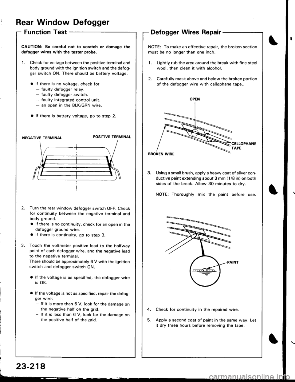
Rear Window Defogger
Function TestDefogger Wires Repair
I
I
CAUTION: Be caretul not to scratch or damage the
defogger wires with the tester probe,
1. Check tor voltage between the positive terminal and
body ground with the ignition switch and the defog-
ger switch ON. There should be battery voltage.
lf there is no voltage, check for
faulty defogger relay.- faulty defogger switch.- faulty integrated control unit.- an open in the BLK/GRN wire.
lf there is battery voltage, go to step 2.
NEGATIVE TERMINALPOSITIVE TEFMINAL
2.Turn the rear window defogger switch OFF. Check
for continuity between the negative terminal and
body ground.
a lf there is no continuity, check for an open in the
defogger ground wire.a lf there is continuity, go to step 3.
Touch the voltmeter positive lead to the halfwaypoint of each delogger wire, and the negative lead
to the negative terminal.
There should be approximately 6 V with the ignition
switch and defogger switch ON,
a lf the voltage is as specified, the defogger wire
is OK.
a lf the voltage is not as specified, repair the defog-ger wire:
lf it is more than 6 V, look for the damage on
the negative half on the grid.
lf it is less than 6 V, look for the damage onthe positive half of rhe grid.
3.
NOTE: To make an elfective repair, the broken section
must be no longer than one inch.
1 . Lightly rub the area around the break with fine steel
wool, then clean it with alcohol.
2. Carefully mask above and below the broken portion
of the defogger wire with cellophane tape.
CELLOPHANETAPE
BBOKEN WIRE
3, Using a small brush, apply a heavy coat of silver con-
ductive paint extending about 3 mm (l /8 in) on both
sides of the break. Allow 30 minutes to dry.
NOTE: Thoroughly mix the paint before use.
Check for continuity in the repaired wire.
Apply a second coat of paint in the same way.
it dry three hours before removing the tape.
Let
OPEN
23-214
Page 1276 of 1680
![ACURA INTEGRA 1998 Service Repair Manual Moonroof
Circuit Diagram
\,
UNDER,HOOD FUSEi RELAY 8OX
No 41 (100A) N0.42 (40A)
IGNIT ON SW]TCH
M
MOONROOF M0TOR (Harchback)
BLK
G201G401
MOONROOF M0TOR (Sedan)
23-220 ACURA INTEGRA 1998 Service Repair Manual Moonroof
Circuit Diagram
\,
UNDER,HOOD FUSEi RELAY 8OX
No 41 (100A) N0.42 (40A)
IGNIT ON SW]TCH
M
MOONROOF M0TOR (Harchback)
BLK
G201G401
MOONROOF M0TOR (Sedan)
23-220](/img/32/56983/w960_56983-1275.png)
Moonroof
Circuit Diagram
\,
UNDER,HOOD FUSEi RELAY 8OX
No 41 (100A) N0.42 (40A)
IGNIT ON SW]TCH
M
MOONROOF M0TOR (Harchback)
BLK
G201G401
MOONROOF M0TOR (Sedan)
23-220
Page 1278 of 1680
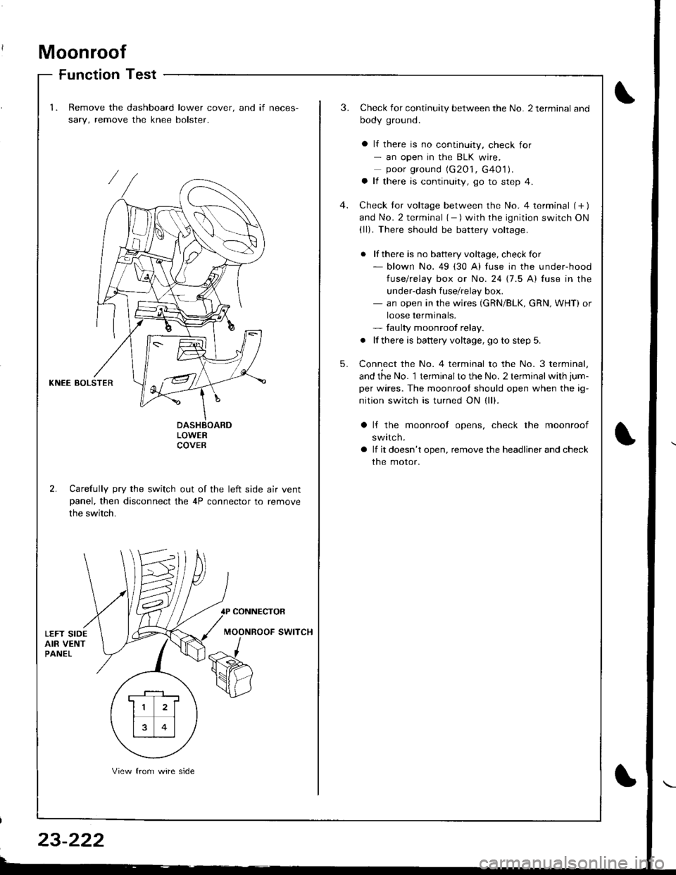
Moonroof
Function Test
1.Remove the dashboard lower cover. and if neces-
sary, remove the knee bolster.
3.Check for continuity between the No. 2 terminal and
body ground.
a lf there is no continuity, check for- an open in the BLK wire.poor ground (G2O1, G4O1).a lf there is continuity, go to step 4.
Check tor voltage between the No. 4 terminal (+ )and No. 2 terminal { - ) with the ignition switch ON(ll). There should be battery voltage.
. lf there is no battery voltage, checkfor- blown No. 49 (30 A) fuse in the under-hood
fuse/relay box or No. 24 17.5 Al fuse in the
under-dash fuse/relay box.- an open in the wires (GRN/BLK, cRN, WHT) or
loose terminals.- faulty moonroof relay.
. lf there is battery voltage, go to step 5.
Connect the No. 4 terminal to the No. 3 terminal,
and the No. 1 terminalto the No. 2 terminal with jum-
per wires. The moonrool should open when the ig-
nition switch is turned ON (ll).
4.
5.
KNEE BOLSTER
LOWERCOVEB
2. Carefully pry the switch out of the left side air ventpanel, then disconnect the 4P connector to remove
the switch.
lf the moonrool opens, check the moonroof
swttcn.
lf it doesn't open, remove the headliner and check
the motor.
CONNECTOR
MOONROOF SWITCH
. F-_1 ,
11 2l
rt�1
13 0l
View from wire side
Page 1281 of 1680
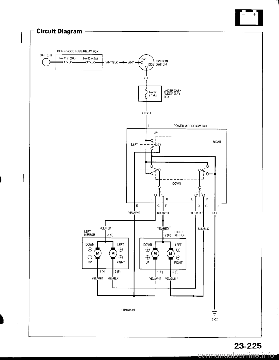
I
Circuit Diagram
UNDER,DASNFUSE/RELAYBOX
YEL
-+-----t
I Zu',x I.I--
POWER MIRROR SWITCH
)
UNDER.HOOD FUSE/FELAY BOX
LEFT -
l_L______ ___l.l
/t\-------- --lt\
YEURED.
( ):Hatchback
23-225
Page 1283 of 1680
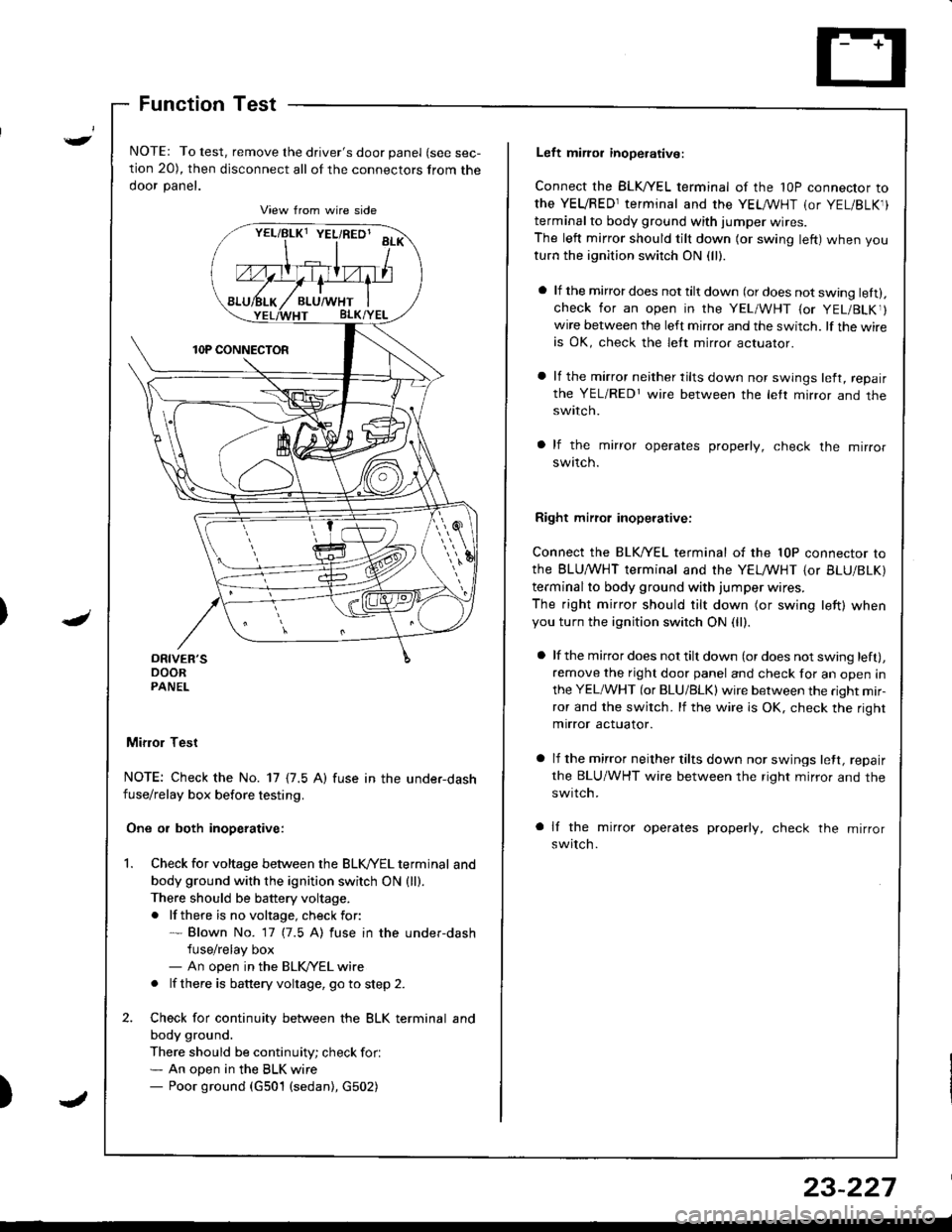
)
Function Test
NOTE: To test, remove the driver's door panel (see sec-
tion 20), then disconnect all of the connectors from the
ooor panet.
Mifior Test
NOTE: Check the No. 17 {7.5 A) fuse in the under-dashfuse/relay box before testing.
One or both inoperative:
Check for voltage between the BLK//EL terminal and
body ground with the ignition switch ON {ll).There should be battery voltage.
. lf there is no voltage, check for:* Blown No. 17 (7.5 A) fuse in the under-dash
fuse/relay box- An open in the BLK/YEL wire
. lf there is battery voltage, go to step 2.
Check for continuity between the BLK terminal and
body ground.
There should be continuity; check for.* An open in the BLK wire- Poor ground (G501 (sedan), G502)
vrllBtxt YEL/RED' aa*\
Left miror inoperative:
Connect the BLK,^/EL terminal of the 1OP connector to
the YEVRED1terminal and the YEL /VHT (or YEL/BLK1)
terminal to body ground with iumper wires.
The left mirror should tilt down (or swing left) when you
turn the ignition switch ON (ll).
a lf the mirror does not tilt down (or does not swing lett).check for an open in the YEL/WHT {or YEL/BLKr}wire between the left mirror and the switch. lf the wireis OK, check the lett mirror actuaror.
a lf the mirror neither tilts down nor swings left, repair
the YEL/REDr wire between the letr mirror and theswtlcn.
a lf the mirror operates properly, check the mirror
swttcn.
Right mirrol inoperative:
Connect the BLK/YEL terminal of the 10P connector to
the BLU,^/VHT terminal and the YELMHT {or BLU/BLK)
terminal to body ground with jumper wires.
The right mirror should tilt down (or swing left) whenyou turn the ignition switch ON (ll).
a lf the mirror does not tilt down (or does not swing left),
remove the right door panel and check for an open in
the YEL/WHT (or BLU/BLK) wire between the right mir-
ror and the switch. lf the wire is OK, check the right
mirror actuator.
a lf the mirror neither tilts down nor swings lett, repair
the BLU/WHT wire between the right mirror and the
swrtch.
a lf the mirror operates properly, check the mirror
switch.
23-227
Page 1284 of 1680

Power Windows
POWER WINDOWMASTER SWITCH(Has built-in control unitiInput Test, page 23-234, 236Iesr, page 23-23'1 ,238Replacement, page 23'239
Component Location Index
UNDER.DASHFUSE/RELAY BOX
DRIVER'STest, page 23-240
LEFT REAR WINDOW MOTOR isedan)Test, page 23 240
POWER WINDOW RELAYTest, page 23-69
LEFT REAR WINDOW SWITCH {Sedan)Test, page 23 238Replacement, page 23 239
FRONT PASSENGER'S WINDOW SWITCHTest, page 23 238Replacement, page 23 239
FRONT PASSENGER'S WINDOW MOTOFTest, page 23-240
RIGHT REAR WINDOW SWITCH (Sedanl
Test, page 23 238Replacement, page 23-239
RIGHT REAR WINOOWMOTOR lsedanlTest, page 23-240
a rrrr'---rnnrn Tl---t----, .----r- L l
(
\
23-230
Page 1285 of 1680
)
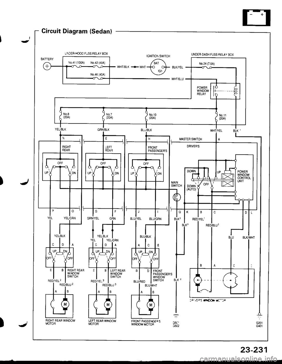
Circuit Diagram (Sedan)
RIGHT REAR WINOOWMOTOR
BLK '
LEFT REAR WINOOWMOTOF)
BLUIRED I swrrcH
UNDEF.HOOD FUSE/RELAY BOXUNDEF DASH FUSE/NELAY BOXIGNITION SWITCH
FRONT PASSENGECSWINDOWMOTOR
:. ,:5S rricot !c-:F
23-231
Page 1289 of 1680
Test conditionPo$sible cause if result is not obtained
)
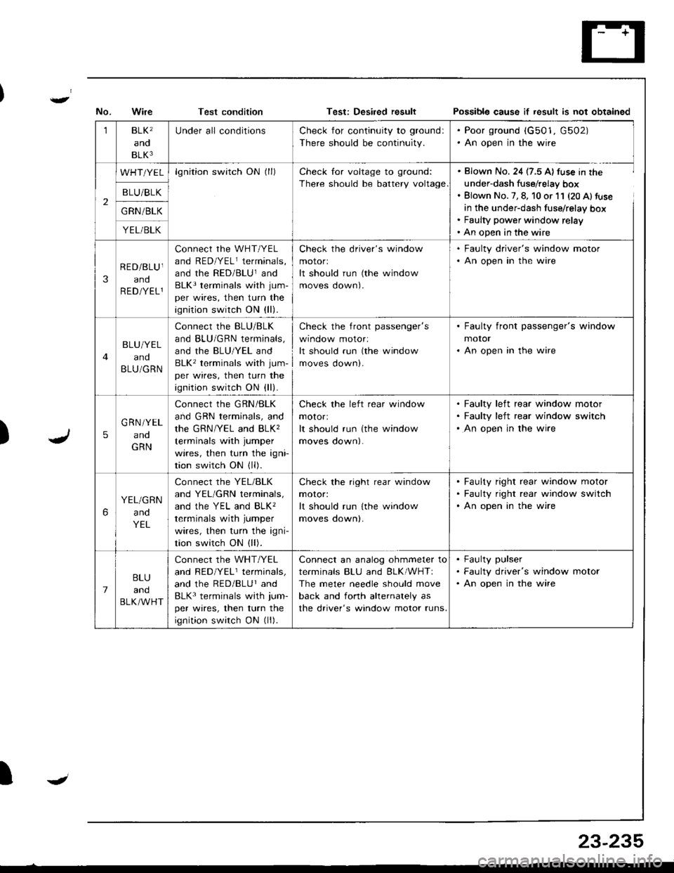
1BLK'
and
BLK3
Under all conditionsCheck for continuity to ground:
There should be continuity.
. Poor ground (G501, G502). An open in the wire
2
WHT/YELlgnition switch ON (ll)Check for voltage to ground:
There should be battery voltage
. Blown No. 24 (7.5 A) fuse in the
under-dash fuse/relay box. Blown No. 7, 8, 10 or 11 (20 Al fuse
in the under-dash fuse/relay box. Faulty power window relay' An open in the wire
B LU/BLK
G RN /BLK
YEL/BLK
3
RED/BLU I
and
R ED/YEL1
connect rhe wHT/YEL
and RED/YELr terminals,
and the RED/BLUland
BLK3 terminals with jum-
per wires, then turn the
ignition switch ON (ll).
Check the driver's window
motorl
It should run (the window
moves oown).
. Faulty driver's window motor. An open in the wire
BLU/YEL
and
BLU/GRN
Connect the BLU/BLK
and BLU/GRN terminals,
and the BLU/YEL and
BLK' terminals with jum-
per wires, then turn the
ignition switch ON (ll).
check the front passenger's
wtnoow molor:
It should run (the window
moves down).
. Faulty front passenger's window
motor. An open in the wire
5
G RN/YEL
ano
GRN
Connect the GRN/BLK
and GRN terminals, and
the GRN/YEL and BLK,
terminals with jumper
wires, then turn the igni
tion switch ON (ll).
Check the left rear window
motor:
It should run {the window
moves down|.
Faulty left rear window motor
Faulty left rear window switch
An open in the wire
6
YEL/GRN
and
YEL
Connect the YEL/BLK
and YEL/GRN terminals,
ANd thc YEL ANd BLK'
terminals with jumper
wires, then turn the igni-
tion switch ON (ll).
Check the right rear window
moror:
It should run lthe window
moves oownl.
Faulty right rear window motor
Faulty right rear window switch
An open in the wire
7
BLU
and
BLK/WHT
Connect the WHT/YEL
and RED/YELr terminals,
and the RED/BLUr and
BLK3 terminals with jum-
per wires, then turn the
ignition switch ON (ll).
Connect an analog ohmmeter to
terminals BLU and BLK/WHTI
The meter needle should move
back and fonh ahernalely as
the driver's window motor runs.
Faulty pulser
Faulty driver's window motor
An open in the wire
IJ
23-235
Page 1290 of 1680
Power
Master
Windows
Switch Input Test (Hatchbackl
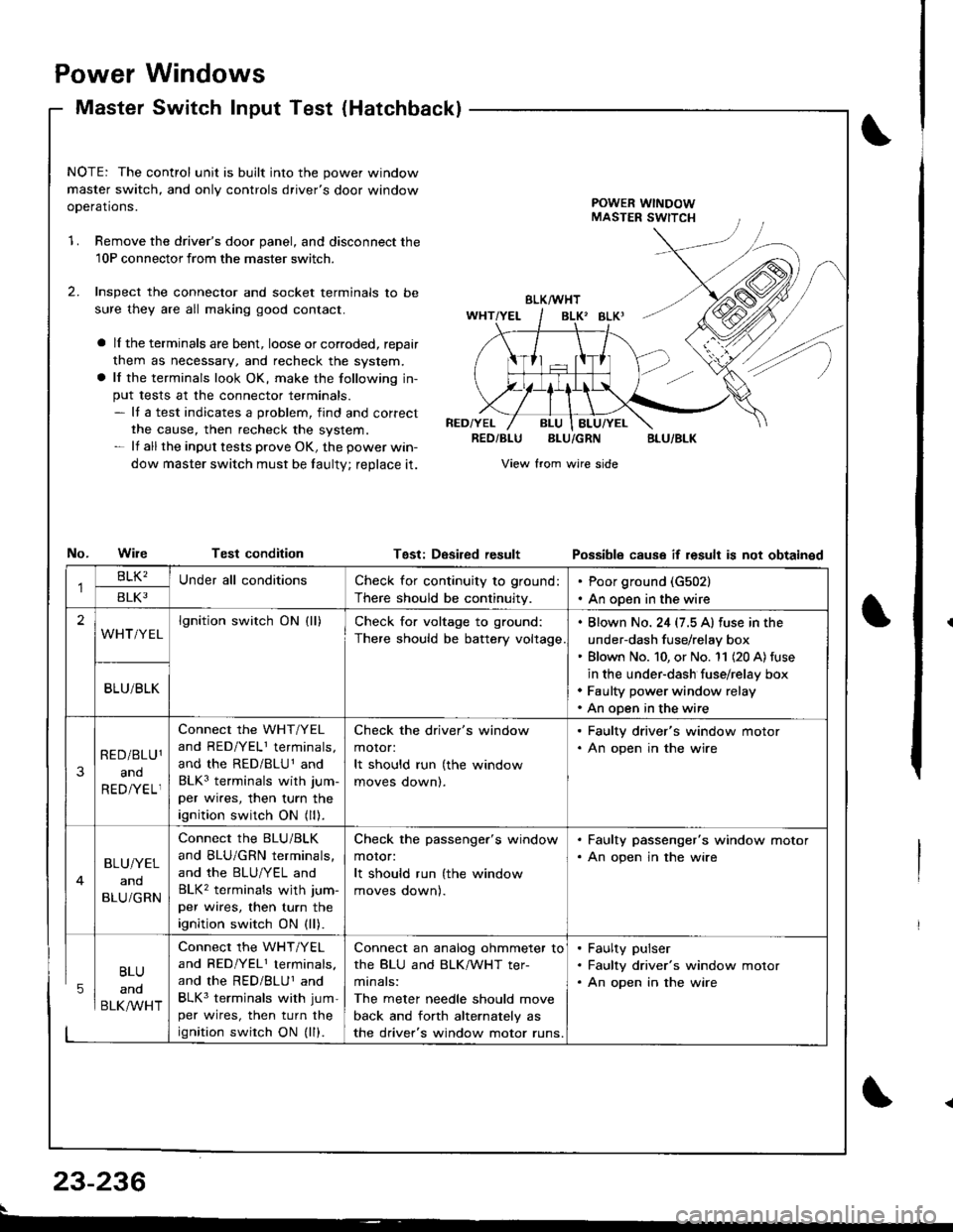
NOTE: The control unit is built into the power window
master switch, and only controls driver's door window
ooerations.POWER WINDOWMASTER SWITCH
1.Remove the driver's door panel, and disconnect the
10P connectorfrom the master switcn.
Inspect the connector and socket terminals to be
sure they are all making good contact.
a lI the terminals are bent, loose or corroded, reDair
them as necessary, and recheck the system.
a lf the terminals look OK, make the following in-
put tests at the connector terminals.- It a test indicates a problem, find and correct
the cause, then recheck the system.- lf all the input tests prove OK, the power win-
dow master switch must be taulty; reDlace it.
No.WileTest condition
BLK/WHT
BLK' BLKI
RED/YELRED/BLUBLU/GRNBLU/BLK
View from wire side
Tgst: DesiredresultPossibls cause if result is not obtainsd
BLU
and
BLK/WHT
Check for continuity to ground:
There should be continuity.
Poor ground (G502)
An open in the wire
lgnition switch ON (ll)Check for voltage to ground:
There should be battery voltage
. Blown No. 24 (7.5 A) fuse in the
under-dash fuse/relay box' Blown No. 10, or No. '11 (20 A) fuse
in the under-dash fuse/relay box. Faulty power window relay. An open in the wire
Connect the WHT/YEL
and RED/YELI terminals,
and the RED/BLU1 and
BLK3 terminals with jum-
per wires, then turn the
ignition switch ON (ll).
Check the driver's window
motor:
It should run (the window
moves oownl.
. Faulty driver's window motor. An open in the wire
Connect the BLU/BLK
and BLU/GRN terminals,
and the BLU/YEL and
BLK2 terminals wjth jum-
per wires, then turn the
ignition switch ON (ll).
Check the passenger's window
motor:
It should run (the window
moves oownl.
. Faulty passenger's window motor. An open jn the wire
Connect the WHT/YEL
and RED/YEL1 terminals.
and the RED/BLUI and
BLK3 terminals with jum-
per wires, then turn the
ignition swirch ON (ll).
Connect an analog ohmmeter to
the BLU and BLK/WHT ter-
minals:
The meter needle should move
back and forth alternately as
the driver's window motor runs.
. Faulty pulser. Faulty driver's window motor. An open in the wire
23-236
Page 1296 of 1680
![ACURA INTEGRA 1998 Service Repair Manual Power Door Locks
Circuit Diagram
@*"
DR]VERS000R LocKSWITCH
NATCN KEYCYLINDER SWITCH
L_____
ooon rocx xroe If7 l
VIKEY
DRIVERSDOOR LOCKACTUATOR
E
UNDER.HOOO FUSEi RELAY BOX
N0.41 (1004) No.s4 (40A)
ACURA INTEGRA 1998 Service Repair Manual Power Door Locks
Circuit Diagram
@*"
DR]VERS000R LocKSWITCH
NATCN KEYCYLINDER SWITCH
L_____
ooon rocx xroe If7 l
VIKEY
DRIVERSDOOR LOCKACTUATOR
E
UNDER.HOOO FUSEi RELAY BOX
N0.41 (1004) No.s4 (40A)](/img/32/56983/w960_56983-1295.png)
Power Door Locks
Circuit Diagram
@*"
DR]VER'S000R LocKSWITCH
NATCN KEYCYLINDER SWITCH
L_____
ooon rocx xroe If7 l
VIKEY
DRIVER'SDOOR LOCKACTUATOR
E
UNDER.HOOO FUSEi RELAY BOX
N0.41 (1004) No.s4 (40A)
DFIVERS DOORKEY CYLJNOERSWITCH
WHT/GRN
FRONTPASSENGERSDOOR LOCKACTUATOR
T--=-l-4{il^
* LEFT REARDOOR LOCKACTUATOR
,@-
* RIGHT NEARDOOR LOCKACTUATOH
-4{.ill^
HATCH LOCKACTUATOR
T-:-lfl.|.{-
LTGRN
LT BLU
A
t--lt=JKEY
i
Atl
T-tl-lKEYBLK
I
G503
.LK BLKll
tlAA
:-l
G501 G2r.G502 ercl
BLK
,l'
G5o1G502
LOCK
o
POWER DOORLOCK CONTROLUNIT
8LK
A-l
G501G502
23-242