relay ACURA INTEGRA 1998 Service Repair Manual
[x] Cancel search | Manufacturer: ACURA, Model Year: 1998, Model line: INTEGRA, Model: ACURA INTEGRA 1998Pages: 1680, PDF Size: 53.14 MB
Page 1235 of 1680
J
)
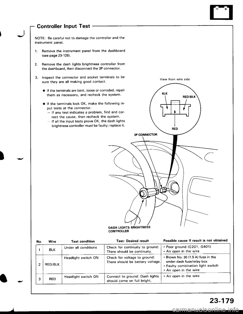
'1.
3.
NOTE: Be careful not to damage the controller and the
instrument panel.
Remove the instrument panel from the dashboard
(see page 23-126).
Remove the dash lights brightness controller from
the dashboard, then disconnect the 3P connector.
Inspect the connector and socket terminals to be
sure they are all making good contact.
a lf the terminals are bent, loose or cortoded, repair
them as necessary, and recheck the system.
a It the terminals look OK, make the following in-
put tests at the connector.- lf any test indicates a problem, find and cor
rect the cause, then recheck the system.
It all the input tests prove OK, the dash lights
brightness controller must be faulty; replace it.
3P CONNECTOR
View lrom wire side
Possible cause if result is not obtainedNo.WireTest condition
CONTROLLEB
Test: Desired resull
BLK
REO
BLKUnder all conditionsCheck for continuity to ground:
There should be continuity.
. Poor ground (G201 , G4O1l. An open in the wire
2REDi BLK
Headlight switch ONCheck for voltage to ground:
There should be battery voltage
Blown No.30 (7.5 A) fuse in the
under-dash fuse/relay box
Faulty combination light switch
An open in the wire
3REDHeadlight switch ONConnect to ground: Dash lights
should come on full bright.
. An open in the ware
l-
)
23-179
Page 1237 of 1680
![ACURA INTEGRA 1998 Service Repair Manual Gircuit Diagram
UNDEF.HOOD FUS gRELAY BOX
(Wilh moonrool)-l
,,**Er
WHT/FED
LT
]NTEGRATED TCoNTROL IUNIT I
lSedan)
.-l
TRUNKL]GHT(sw)
I
lff
lh
iT
Lir -
lb
.F
23-141 ACURA INTEGRA 1998 Service Repair Manual Gircuit Diagram
UNDEF.HOOD FUS gRELAY BOX
(Wilh moonrool)-l
,,**Er
WHT/FED
LT
]NTEGRATED TCoNTROL IUNIT I
lSedan)
.-l
TRUNKL]GHT(sw)
I
lff
lh
iT
Lir -
lb
.F
23-141](/img/32/56983/w960_56983-1236.png)
Gircuit Diagram
UNDEF.HOOD FUS gRELAY BOX
(Wilh moonrool)-l
,,**Er
WHT/FED
LT
]NTEGRATED TCoNTROL IUNIT I
lSedan)
.-l
TRUNKL]GHT(sw)
I
lff
lh
iT
Lir -
lb
.F
23-141
Page 1239 of 1680
)
I
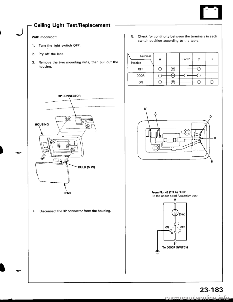
With moonroof:
1. Turn the light switch OFF.
2. Pry off the lens.
3. Remove the two mounting nuts, then pull out the
housing.
5. Check for continuity between the terminals in each
switch position according to the table.
From No. 43 l?.5 A) FUSE(ln the undeFhood fuserelay box)
4. Disconnect the 3P connector from the housing.
Teminal
t"",t*
-l\BorB'cD
OFFo---o\-/
DOORo-/:\--o\:./
ONo-/:\--o\:,/
3P CONNECTOR
LENS
CeilingLightTest/Replacement
23-183
Page 1240 of 1680
Ceiling/Trunk/Cargo Area Lights, Spotlights
Ceiling Light Test/Replacement
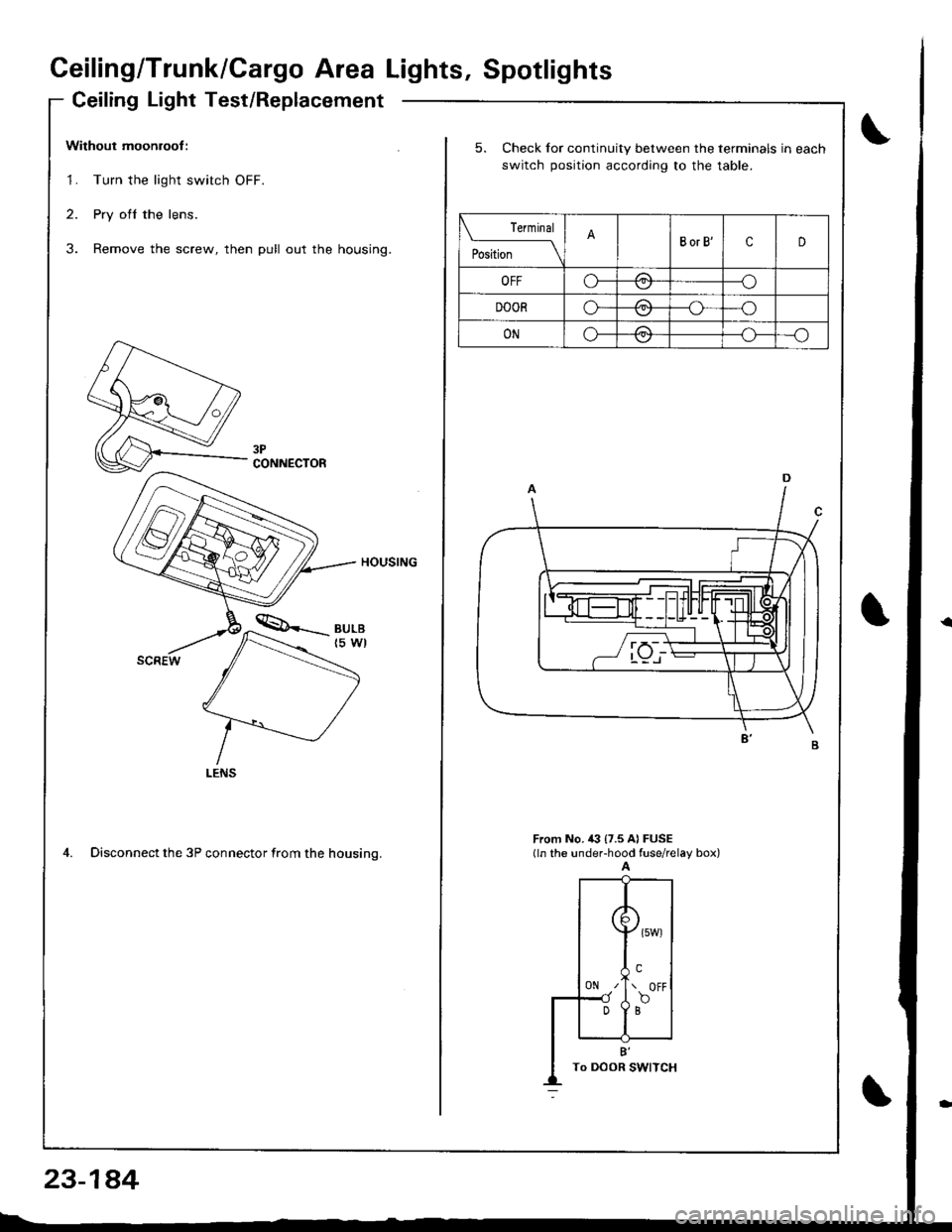
Without moonroof :
1. Turn the light switch OFF.
2. Pry ofl the lens.
3. Remove the screw, then pull out the housing.
HOUSING
4. Disconnect the 3P connector from the housino.
CONNECTOR
23-1a4
5. Check for continuity between the terminals in each
switch position according to the table.
rermrnal
PositionBorB'cD
OFFo-/1--o
DOORo-/A--o
ONo-/a\--o\:,,/--{.J-
From No, i(} {7.5 A} FUSE(ln the under-hood fuse/relay box)A
({
0N z'
Dl
\>l
( owt
!.\. OFF
f,o
B'To DOOR I
Page 1243 of 1680
![ACURA INTEGRA 1998 Service Repair Manual Back-up Lights
Circuit Diagram
IGNITIONswlTcHUNOER.HOOD FUSEi RELAY BOX
EACK.UPLIGHTswtTcH/ / on lhe \r I ransnBgon I
GRN/BLK
IIJ
TRAILERL]GHT NGCONNECTOR
GRN/BLK
IzA arcx.upI P LIGHTS
f
r:zce21
I ACURA INTEGRA 1998 Service Repair Manual Back-up Lights
Circuit Diagram
IGNITIONswlTcHUNOER.HOOD FUSEi RELAY BOX
EACK.UPLIGHTswtTcH/ / on lhe \r I ransnBgon I
GRN/BLK
IIJ
TRAILERL]GHT NGCONNECTOR
GRN/BLK
IzA arcx.upI P LIGHTS
f
r:zce21
I](/img/32/56983/w960_56983-1242.png)
Back-up Lights
Circuit Diagram
IGNITIONswlTcHUNOER.HOOD FUSEi RELAY BOX
EACK.UPLIGHTswtTcH/ / on lhe \r I ransnBgon I
GRN/BLK
IIJ
TRAILERL]GHT NGCONNECTOR
GRN/BLK
IzA arcx.upI P ' LIGHTS
f
r:zce'21
IBLK
II
I
G503
YEL
I
SnoriARr*r.r r*i(3;f;iil're' )V(oN h posirion [E )
l"
IGRN/BLK
23-147
)
I
Page 1244 of 1680
Back-up Lights
Test
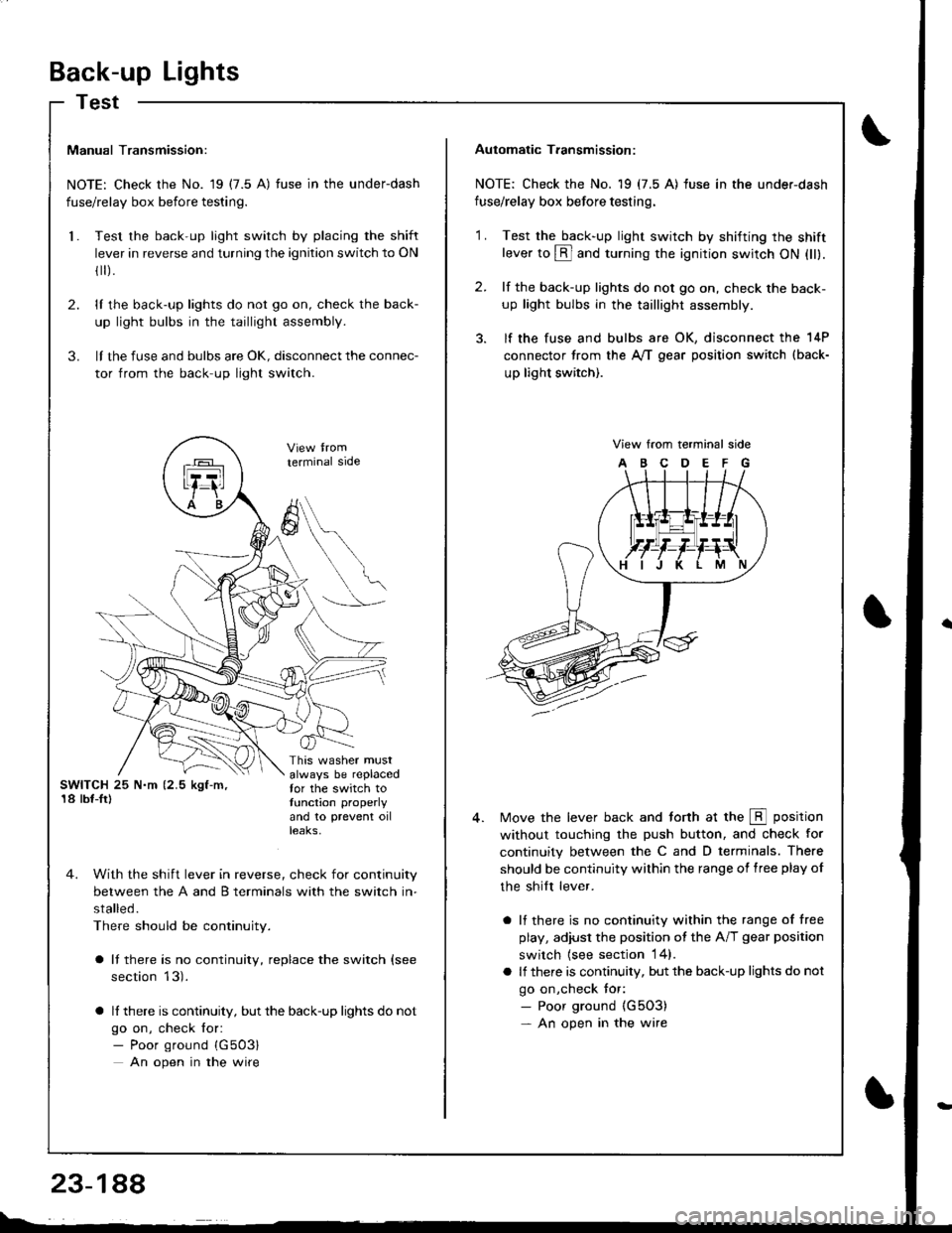
Manual Transmission:
NOTE: Check the No. 19 (7.5 A) fuse in the underdash
fuse/relay box before testing.
Test the back-up light switch by placing the shift
lever in reverse and turning the ignition switch to ON
fl r).
lI the back-up lights do not go on, check the back-
up light bulbs in the taillight assembly.
lI the fuse and bulbs are oK, disconnect the connec-
tor from the back-up light switch.
2.
3.
l.
SWITCH 25 N.m (2.5 kgf-m,'18 lbf-Ir)
This washer mustalways be replacedfor the switch totunction properly
and 10 prevent oilteaKs,
terminal side
4. With the shift lever in reverse, check for continuity
between the A and B terminals with the switch in-
stalled.
There should be continuity.
a It there is no continuity, replace the switch (see
section 13).
a lf there is continuity, but the back-up lights do not
go on, check for:- Poor ground {G503}
An open in the wire
A
6
Automatic T.ansmission:
NOTE: Check the No. 19 (7.5 A) fuse in the under-dash
fuse/relay box before testing.
2.
'1 .Test the back-up light swirch by shifting the shiftlever to @ and turning the ignition switch ON (ll).
lf the back-up lights do not go on, check the back-
up light bulbs in the taillight assembly.
lf the fuse and bulbs are OK, disconnect the 14P
connector from the A,/T gear position switch (back-
up light switch).
View from terminal side
ABCDEFG
Move the lever back and torth at the E position
without touching the push button, and check for
continuity between the C and D terminals. There
should be continuity within the range of free play of
the shilt lever.
a lf there is no continuity within the range of free
play, adiusl the position ot the A/T gear position
switch {see section 14}.
a lf there is continuity, but the back-up lights do not
go on,check tor:- Poor ground {G5O3)- An open in the wire
Page 1245 of 1680
)
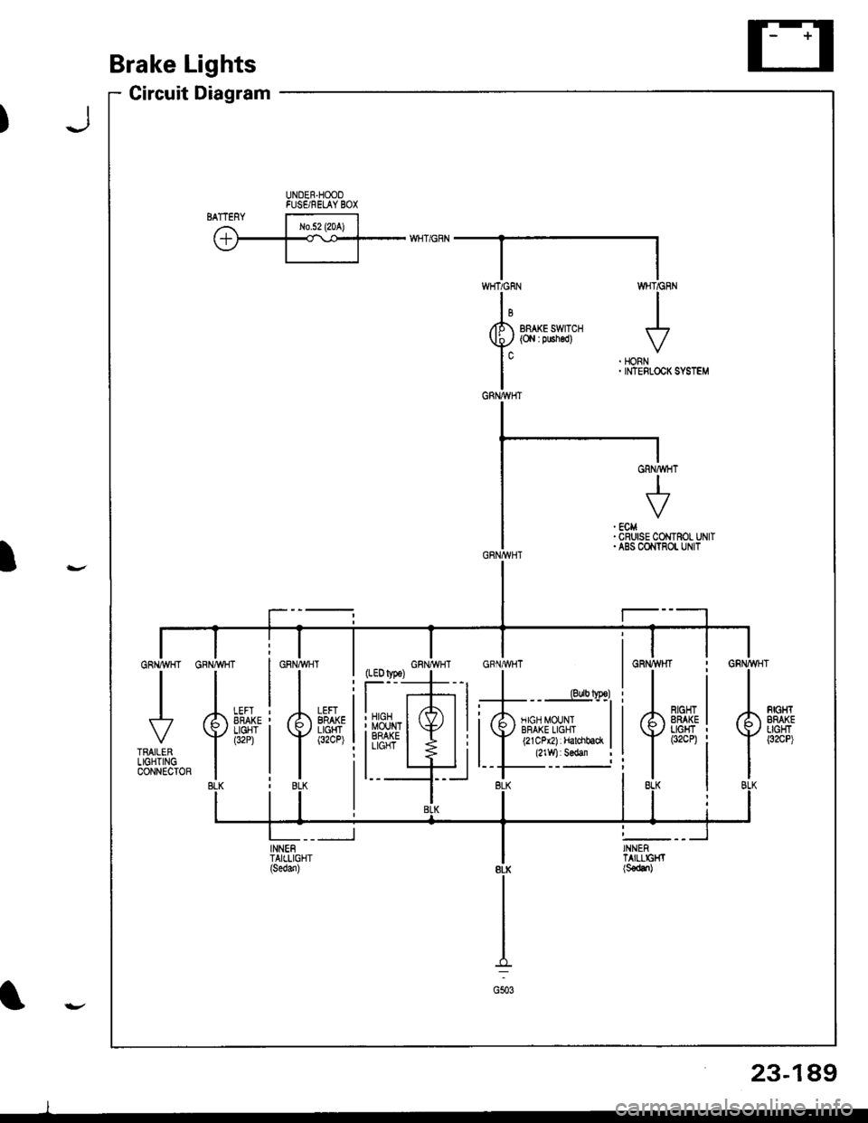
Brake Lights
Circuit Diagram
UNDER.HOOOFUSE/RELAY BOX'ry
BRAKE SWITCH(O,l I pushed)
WHT/GF
I
HONNINTEFLOCK
,#�,.^{.
LEFIBRAKELIGHT(32CP)il
:li
l_t
INNENTAIILIGHT
WHTiGRN
GRNA{HT
J
GRNMHT
23-189
l
I
Page 1246 of 1680
Brake
Brake
Lights
Switch TestHigh Mount Brake Light Replacement
\
t
2.
t.
3.
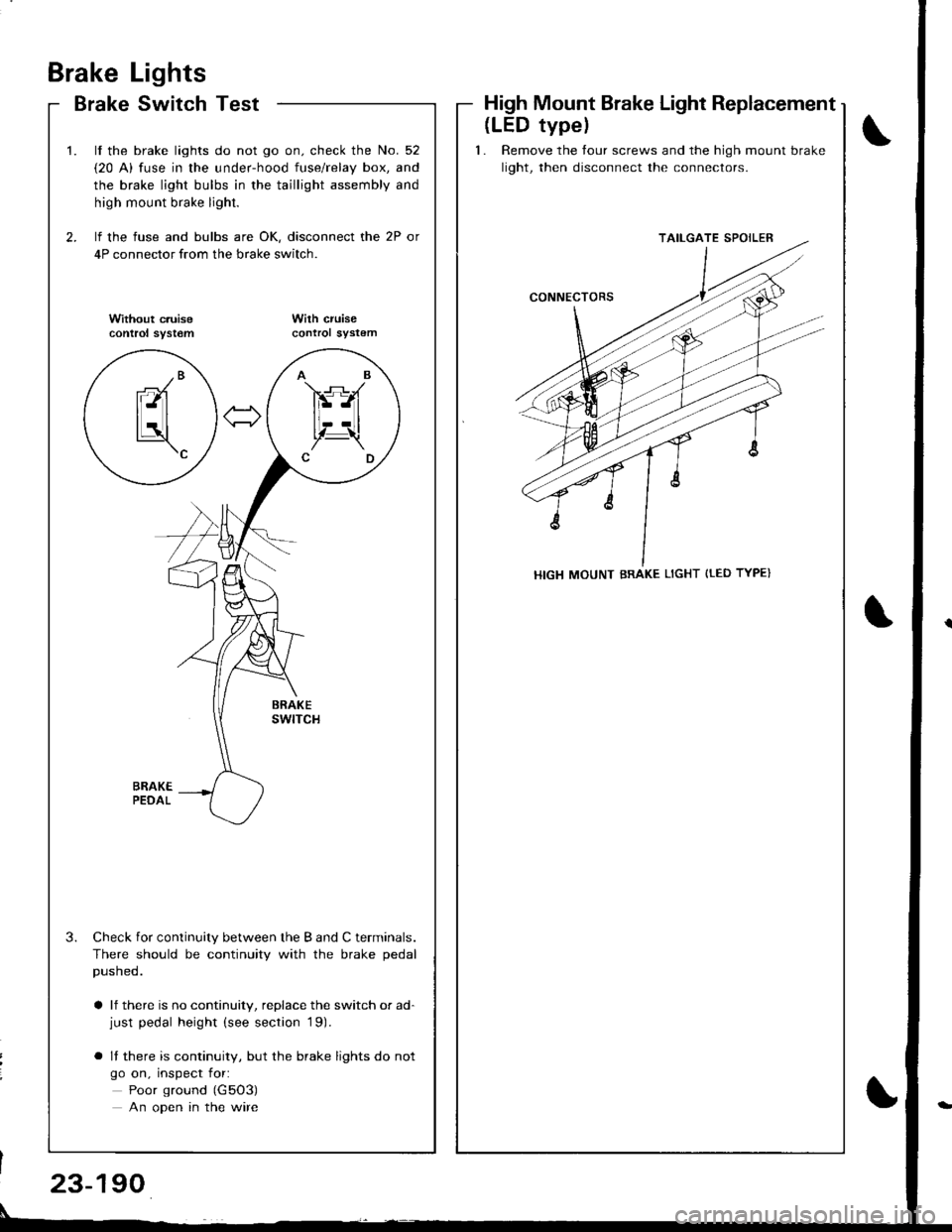
lf the brake lights do not go on. check the No. 52
{20 A) fuse in the under-hood fuse/relay box, and
the brake light bulbs in the taillight assembly and
high mount brake light.
lf the fuse and bulbs are OK, disconnect the 2P or
4P connector from the brake switch.
Without c.uisecontrol syst€mWilh cruisecontrol sYstem
Check for continuity between the B and C terminals.
There should be continuity with the brake pedal
pusneo.
a lf there is no continuity, replace the switch or ad-just pedal height (see section '19).
o It there is continuity, but the brake lights do not
go on, inspect for:
Poor ground (G5O3)
An open in the wire
AB
FS-A
lt--Ltl, t!,Z-\CD
-/Branl-ltl
tLatl\c
(LED typel
1. Remove the tour screws and the high mount brake
light, then disconnect the connectors.
TAILGATE SPOILER
HIGH MOUNT BRAKE LIGHT {tED TYPE}
23-190
Page 1248 of 1680
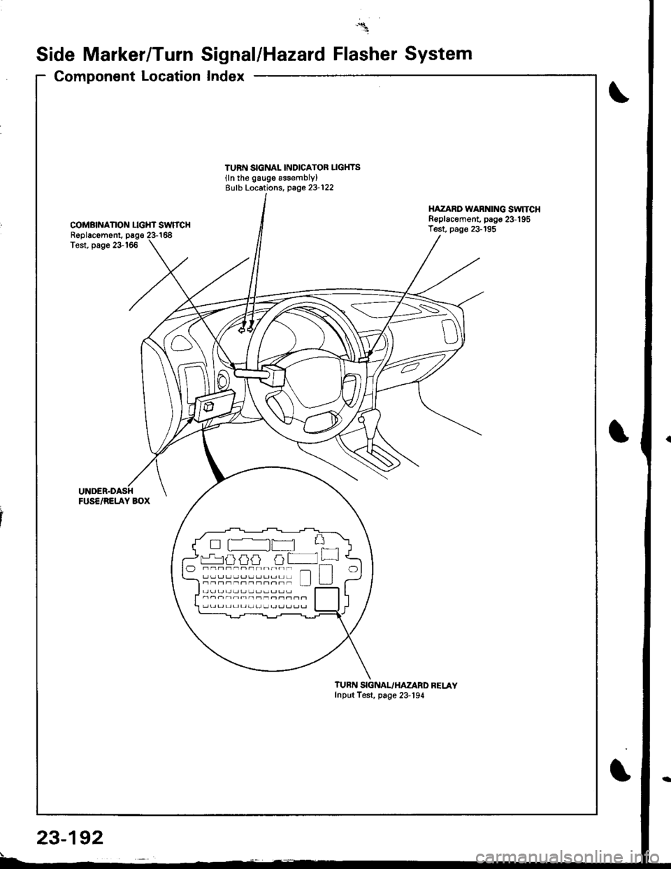
Side Marker/Turn Signal/Hazard Flasher System
Component Location
TURf{ SIGNAL INDICATOF LIGHYS(ln the gaugo assembly)Eulb Locations, page 23-122
COMBNANON LIGHT SWTTCHReplacement. page 23-168Test, page 23-166
FUS€/RELAY BOX
HAZARD WARNING SWITCHReplacement, pago 23-195Test, pag€ 23-195
il
r-.1uuij tjt +ffi-------r--- _ ntll----------rn LJJ u
?UBN SIGNAL/HAZARD RELAYInput Test, page 23-'194
I
23-192
Page 1250 of 1680
Side Marker/Turn Signal/Hazard Flasher System
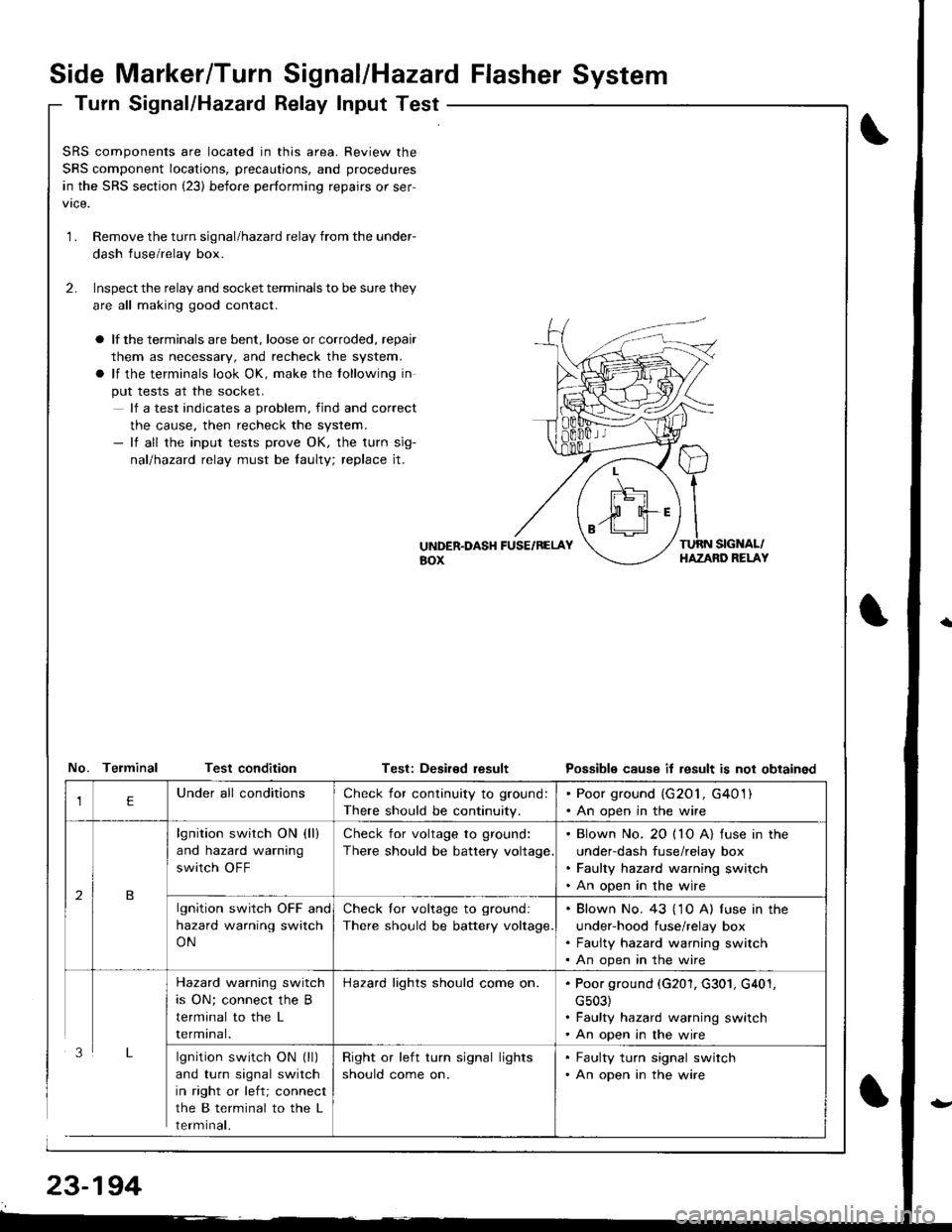
Turn Signal/Hazatd Relay Input Test
\
t
SRS components are located in this area. Review the
SRS component locations, precautions, and procedures
in the SRS section (23) before performing repairs or ser-
1.Remove the turn signal/hazard relay from the under-
dash fuse/relay box.
Inspect the relay and socket terminals to be sure they
are all making good contact.
a lf the terminals are bent, loose or corroded, repair
them as necessary, and recheck the system.
a lf the terminals look OK, make the tollowing in
put tests at the socket.
lf a test indicates a problem, find and correct
the cause, then recheck the system.- lf all the input tests prove OK, the turn sig-
nallhazad relay must be faulty; replace jt.
2.
UiTDER.DASH FUSE/RELAYaox
TURN SIGNAL/HAZAND RELAY
No. Telminal Test conditionTest: Deaired resultPossible cause it result is not obtained
lgnition switch ON (ll)
and turn signal switch
in right or left; connect
the B terminal to the L
rermtnat,
Check for continuity to ground:
There should be continuity.
. Poor ground (G201, G401). An open in the wire
lgnition switch ON (ll)
and hazard warning
switch OFF
Check for voltage to ground:
There should be battery voltage
. Blown No. 20 ( 10 A) fuse in the
under-dash fuse/relay box. Faulty hazard warning switch. An open in the wire
lgnition switch OFF and
hazard warning switch
ON
Check lor voltage to ground:
There should be battery voltage.
. Blown No. 43 ('1 0 A) f use in the
under-hood fuse/relay box. Faulty hazard warning switch. An open in the wire
Hazard warning switch
is ON; connect the B
terminal to the L
rermtnat.
Hazard lights should come on.. Poor ground (G201, G301, G401,
cs03). Faulty hazard warning switch. An open in the wire
Right or left turn signal lights
should come on.
. Faulty turn signal switch. An open in the wire